
FLOATS AND FITTINGS
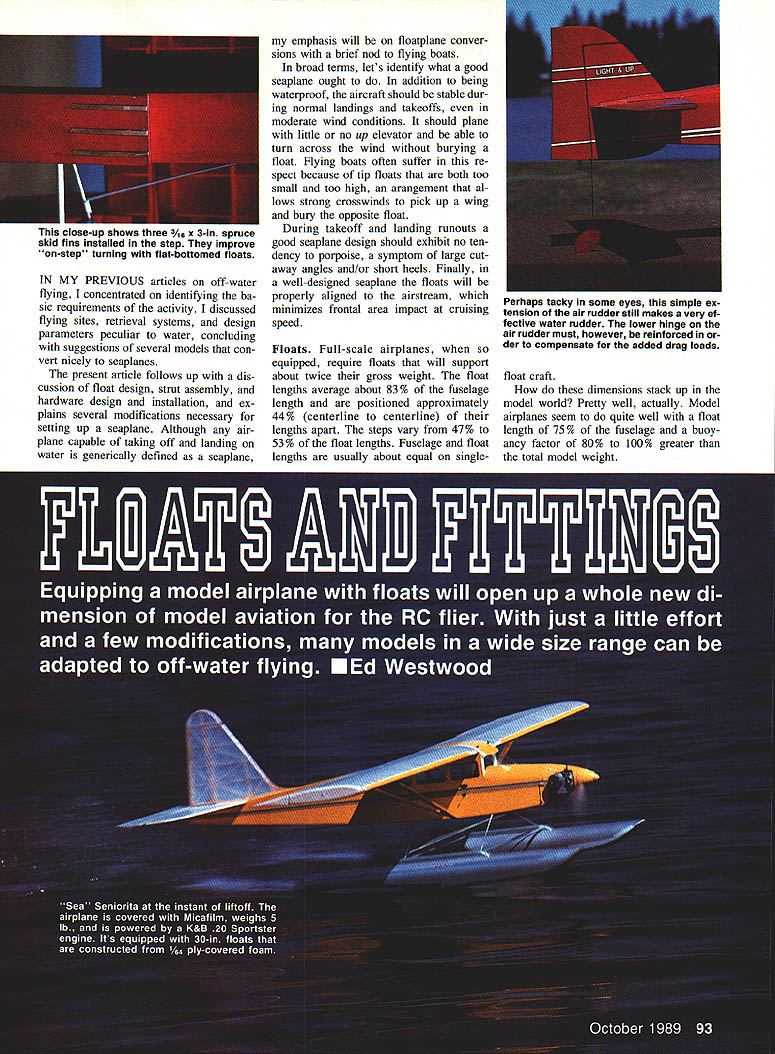
Equipping a model airplane with floats opens a whole new dimension of model aviation for the RC flier. With a little effort and a few modifications, many models in a wide size range can be adapted to off-water flying. — Ed Westwood
In previous articles on off-water flying I discussed flying sites, retrieval systems, and design parameters peculiar to water, and suggested several models that convert nicely to seaplanes. This article follows up with a discussion of float design, strut assembly, hardware design and installation, and explains several modifications necessary for setting up a seaplane. Although any airplane capable of taking off and landing on water is generally defined as a seaplane, the emphasis here is on floatplane conversions with a brief nod to flying boats.
A good seaplane should be waterproof, stable during normal landings and takeoffs (even in moderate wind), plane with little or no up elevator, and be able to turn across the wind without burying a float. It should not porpoise during takeoff and landing runouts (a symptom of large cutaway angles and/or short heels). Finally, the floats should be properly aligned to the airstream to minimize frontal-area drag at cruise.
Floats
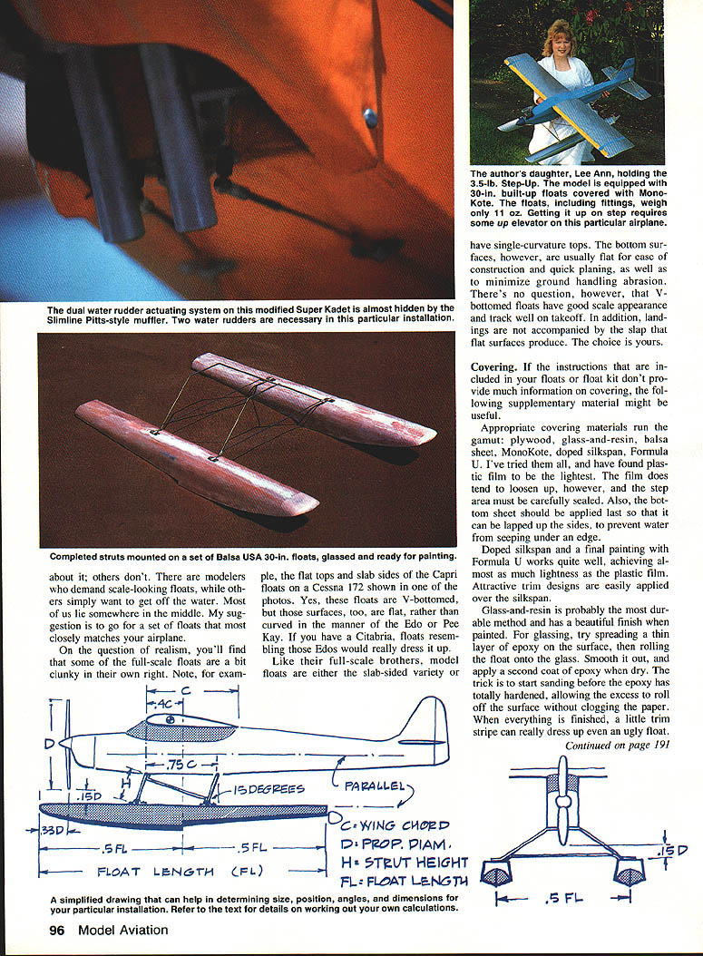
Full-scale float-equipped airplanes typically require floats that will support about twice their gross weight. Float lengths average about 83% of fuselage length and are positioned roughly 44% (centerline to centerline) of the fuselage length apart. Steps vary from 47% to 53% of the float length. Single-float craft usually have fuselage and float lengths about equal.
Model airplanes generally do well with a float length of about 75% of the fuselage and a buoyancy factor of 80% to 100% greater than the total model weight.
To determine a proper float length for a given model, work from the plans:
- Drop a line vertically down from the 40% mean aerodynamic chord (MAC) point.
- Drop a second line from a point one-third of the prop diameter ahead of the prop.
- Twice the distance between these two lines becomes your float length.
This should come out fairly close to 75% of your fuselage length. The step will usually be positioned a little rearward of the center of gravity (CG). If you must compromise, move the step forward to the CG rather than shortening the float tips.
When evaluating ready-made floats, request brochures from manufacturers and check length, weight range, compatible engine sizes, and whether the floats come finished. Molded floats tend to be heavier than built-up or foam-covered units.
Examples and considerations:
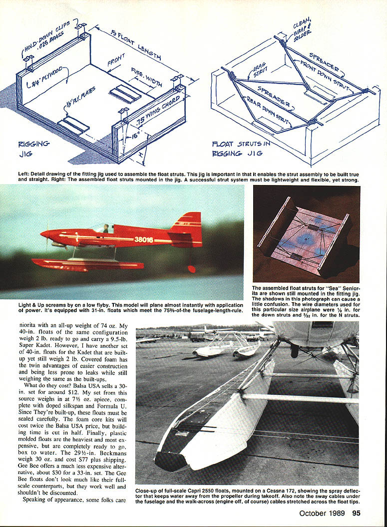
- My 31-in., 3/4-in.-plywood-covered foam floats (including attach fittings, covering, and paint) weigh 15 oz. The Sea Seniorita has an all-up weight of 74 oz. My 40-in. floats of the same configuration weigh 2 lb. ready to go and carry a 9.5-lb Super Kadet. Another set of built-up 40-in. floats for the Kadet also weighs about 2 lb.
- Covered-foam floats are easier to construct and less prone to leaks while weighing about the same as built-ups.
- Balsa USA sells a 30-in. set for around $12; my set from them weighs about 7.5 oz. apiece (doped silkspan and Formula U). Foam-core kits cost roughly twice that but cut building time in half. Plastic molded floats are the heaviest and most expensive but are ready to go out of the box (example: 29½-in. Beckman floats weigh 30 oz. and cost about $77 plus shipping). Gee Bee offers an inexpensive 33-in. set for about $30.
Appearance and finishing:
- If you want a smooth, prototypical finish, cover foam floats with 1/32- or 1/64-in. balsa sheeting, glass cloth, or thin plywood. Balsa is lightest but tricky; glass cloth is tough and waterproof but heavier; plywood offers a good appearance and is relatively easy.
- Some modelers demand scale-looking floats, others just want function; many lie between these extremes. Choose floats that match your airplane as closely as practicable.
Full-scale floats sometimes look clunky (flat tops and slab sides), and models mimic that variety. Model floats are often slab-sided or have single-curvature tops. Bottom surfaces are usually flat for ease of construction and quick planing and to minimize ground-handling abrasion. V-bottomed floats have better scale appearance, track well on takeoff, and produce less slap on landing; choice is up to you.
Covering
If your float kit doesn't provide covering instructions, consider these options: plywood, glass-and-resin, balsa sheet, MonoKote, doped silkspan, Formula U, and plastic film.
- Plastic film is the lightest covering but can loosen over time; the step area must be carefully sealed. Apply the bottom sheet last so it laps up the sides to prevent water seepage under an edge.
- Doped silkspan with a final coat of Formula U is nearly as light as plastic film and accepts attractive trim work easily.
- Glass-and-resin (glassing) is the most durable and provides a beautiful finish when painted. For glassing: spread a thin layer of epoxy on the surface, roll the float onto the glass, smooth it out, and apply a second coat when dry. Start sanding before the epoxy is fully hardened so excess resin rolls off without clogging the paper. A little trim stripe can dress up the finished float.
Positioning and Fittings
Correct float positioning must be worked out before mounting fittings. Return to the plans and add to the sketch used to determine float length.
- Starting with the prop in its correct position, measure 15% of the prop diameter below the bottom of the prop and draw a line parallel to the fuselage axis. That marks the top of the floats.
- For a Sea Seniorita using a 10 x 4 or 10 x 5 prop, the top of the floats will be 1-1/2 in. from the bottom of the prop.
- An Eagle 63 turning an 11 x 5 prop will require about 1-3/4 in.
- Position the step at 40% of the MAC (or 40% of the chord if the wing is rectangular). The float tips should be about one-half (or a little less) of the prop diameter aft of the prop. The more float forward of the prop (without excess), the better the planing characteristics.
Most built-up floats have internal hardbacks; if so, you can install spreaders anywhere you please. Exposed hardbacks (as on some ready-made floats) require determining their location in advance.
Fittings: simplicity is the key—simple, well-made fittings give maximum lightness and strength and a neater appearance. Note differences from full-scale fittings:
- Full-scale installations use pin-jointed down and N struts that carry only tension/compression; side loads are taken by cable cross bracing. Spreaders are hollow extrusions filled for stiffness.
- On models, down struts, N/drag struts, and spreaders are normally designed to flex and carry side loads; the N struts carry drag loads and spreaders hold the floats parallel and resist separation. The model installation appears flimsy but the flexibility absorbs impact and prevents breakage on hard landings.
Use the back of your plans to sketch the fuselage gross section at the wing leading edge and draw the hardbacks into the fuselage. Position float centerlines about one-half of the float inboard apart (centerline to centerline). Determine hardback locations and draw in the down strut positions. If using ready-made floats with attaching stock, begin measurements from those fittings; if the provided fittings can't be bent to fit your drawing, make new ones.
On most high-wing planes, the rear strut is about the same length as the front and is positioned about three-fourths of a wing chord back. If the fuselage bottom isn't horizontal between front and rear struts, draw another fuselage cross section where the rear strut attaches and fashion a slightly different rear strut.
Fabrication — Bending Wire and Making Struts
Wire sizes and preparation:
- Use 5/32-in. dia. wire for planes up to about 6 lb. and 3/32-in. dia. wire for models up to about 10 lb. (adjust size by model weight). A .40-size plane typically uses 5/64-in. dia. wire; a single 36-in. piece can be enough for both struts.
- Cut wire with a Dremel cut-off wheel, mark bends, and form using a vise and hammer with a cardboard template from your drawings. Overbend slightly and then pull back to relieve residual stresses. Make N struts from wire one size smaller than the down struts (larger size is unnecessary for drag loads).
- Spreaders can be made from the same diameter wire as the down struts; they can be wrapped with No. 24 copper wire and soldered across the bottom, or ends can be bent to sit just inboard of the floats so N struts can be wrapped simultaneously around the rear spreader.
Preferred spreaders:
- Arrow shafts are a good option—available in several diameters and typically 32 in. long. I use 3/16-in. shafts for .40-.60-size machines. Fiberglass shafts are very tough, even after drilling.
Assembly sequence:
- Cut shafts to the spreader width. Airplanes in the .40-size range usually take 16-in. spreaders, allowing both spreaders to come from one shaft.
- Drill holes for the down strut axles in the spreaders; twist the drill to elongate the holes, then slit one end of each shaft from the hole partway to the edge.
- File notches in the axle areas on the down struts and put tufts of cotton on the shafts just inboard of the holes.
- Slide one axle end into the unslit hole, bend the strut while inserting the other axle into the slit hole (bevel the top of the axle if necessary).
- Mix JB Weld, warm the joint with a heat gun, and coax JB Weld into the joint. Tape the end and fit remaining axles similarly.
Build a fitting jig—essential for getting the assembly straight. The jig can be made quickly with a table saw and should follow your assembly drawing dimensions.
Lock spreader assemblies in the jig while fitting and soldering the N struts. Use a bent coat hanger as a master pattern for shaping N struts. When satisfied, cut and bend the N struts to match the master.
With spreaders locked in the jig, butt the solder areas and N strut ends, wrap in place with No. 24 copper wire (about 20 in. per joint), and solder using a soldering gun (not a torch, which deposits carbon and prevents good solder flow). Clean up joints after soldering. The strut assembly is then ready for mounting.
Mounting
Place floats on a board, lock them down, and position the strut assembly on the floats. Attach with small straps or, if floats have exposed hardbacks, through prepared holes.
Secure the assembly to the airplane by screwing landing gear straps over the down struts into the fuselage. A useful technique is to mount the strut, back out the screws, fill the holes with cyanoacrylate (CyA) glue, then resecure the screws.
Water Rudders
Whether steering a nose-wheel airplane or a taildragger, water rudders are straightforward.
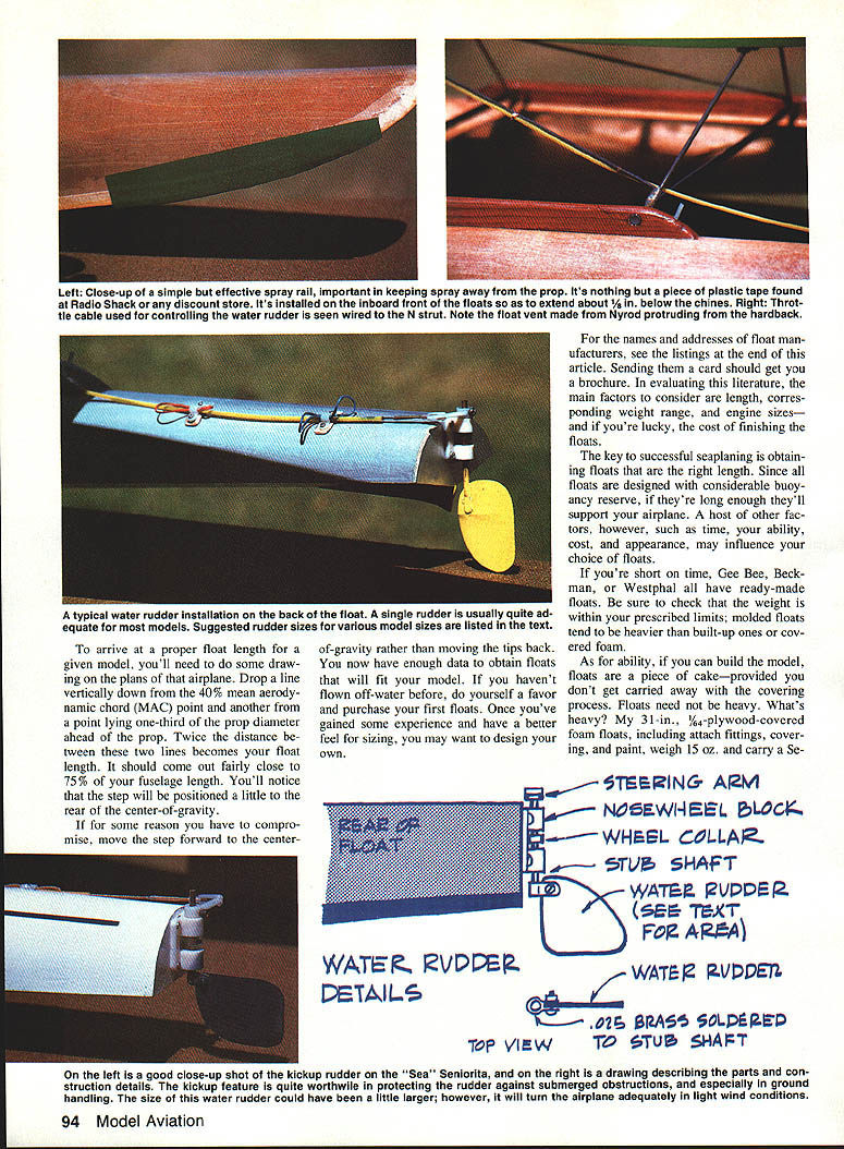
- Nose-wheel aircraft: replace the nose wheel with a stub shaft extending about 1/2 in. below the fuselage and install another steering arm. Run a length of steering cable from the steering arm along the nose, down the N strut, and along the float length.
- Taildraggers: hook a length of steering cable to the rudder horn and attach it to the fuselage with small aluminum clips or tape. Bend the sleeve down past the rear down strut and along the float, securing it with two landing gear straps.
A simple extension below the air rudder makes the easiest water rudder (tacky-looking but effective). A .40-size model will require 3/32-in. dia. wire and a reinforced lower air-rudder hinge. If you have a sub-rudder, run the shaft extension through a lower bearing to reduce drag loads on the lower hinge.
The kick-up feature (allowing the rudder to trail in the water and kick up for obstructions) is worth the effort. Some kits include a kick-up unit; small commercial units are available but may require modification.
To make a water rudder you typically need a 1/8-in. Du-Bro or Goldberg nose-wheel steering block, a stub shaft, collar, another arm, and some brass stock.
John Sullivan suggests the following water-rudder sizes as effective for steering:
- 1.25 sq. in. for .20–.32-size planes
- 2.25 sq. in. for .40-size
- 3.25 sq. in. for .60-size
- 4 sq. in. for .90-size
- 4.5 sq. in. for 1.20-size
Most model installations use a single water rudder, but paired rudders can be used to improve turning moment—if so, use the sizes indicated above.
Last Hints Department
- Waterproofing: apply a finger fillet of clear silicone along the fuselage/stabilizer juncture and a little around the hinges. Do not use silicone around steel struts—it is corrosive to metal.
- Add skid fins or battens on flat-bottomed floats extending forward a couple of inches from the steps to give the water rudder better leverage.
- Spray rails deflect water away from the prop. Plastic tape (from discount stores or Radio Shack) works well—apply a strip along the inboard fronts and trim it to extend about 1/8 in. below the chines.
- Engines and props: four-stroke engines work, but two-strokes give a better power-to-weight ratio. Long, low-pitch props are generally available only in wood; I use wood props and trim tips if necessary, rebalancing when needed.
- Prop recommendations (personal experience):
- 10 x 4 for .20-size engines
- 11 x 5 or 12 x 4 for .25 engines
- 11 x 5 or 12 x 4 for .29–.40 engines (louder)
- 13 x 5, or 14 x 5 cut down to 13 x 5, for .60-size engines
If your plane won't lift off in less than 100 ft.:
- Ensure you're using a seaplane prop.
- Remove a little downthrust, if any.
- Put small shims under the front downstruts to raise the nose slightly (full-size installations often do this to offset power loss from floats).
- Consider going to an engine one size larger—this is often a good idea for first builds.
Once you've taxied a floatplane up to the shore you'll likely wonder why you waited so long. Go for it!
Model Float Manufacturers
- Ace R/C, 116 W. 19th St., P.O. Box 511, Higginsville, MO 64037
- Balsa USA, P.O. Box 164, Marinette, WI 54143
- Beckman Floats / Hobby Lobby International, 5615 Franklin Pike Circle, Brentwood, TN 37027
- Bill Westphal Floats / The Float Place, 6301 234th Pl. SW, Mountlake Terrace, WA 98043
- Carl Goldberg Models, Inc., 4734 West Chicago Ave., Chicago, IL 60651
- Gee Bee Products, P.O. Box 18, East Longmeadow, MA 01028
- Great Planes Model Mfr. Co., P.O. Box 721, Urbana, IL 61801
- John Sullivan Model Floatplane Products, 1421 Second Street, Calistoga, CA 94515
- Len's RC Enterprises, Box 214, Montrose, B.C., Canada V0G 1P0
Transcribed from original scans by AI. Minor OCR errors may remain.

