
FLOP
By Kirk Robinson
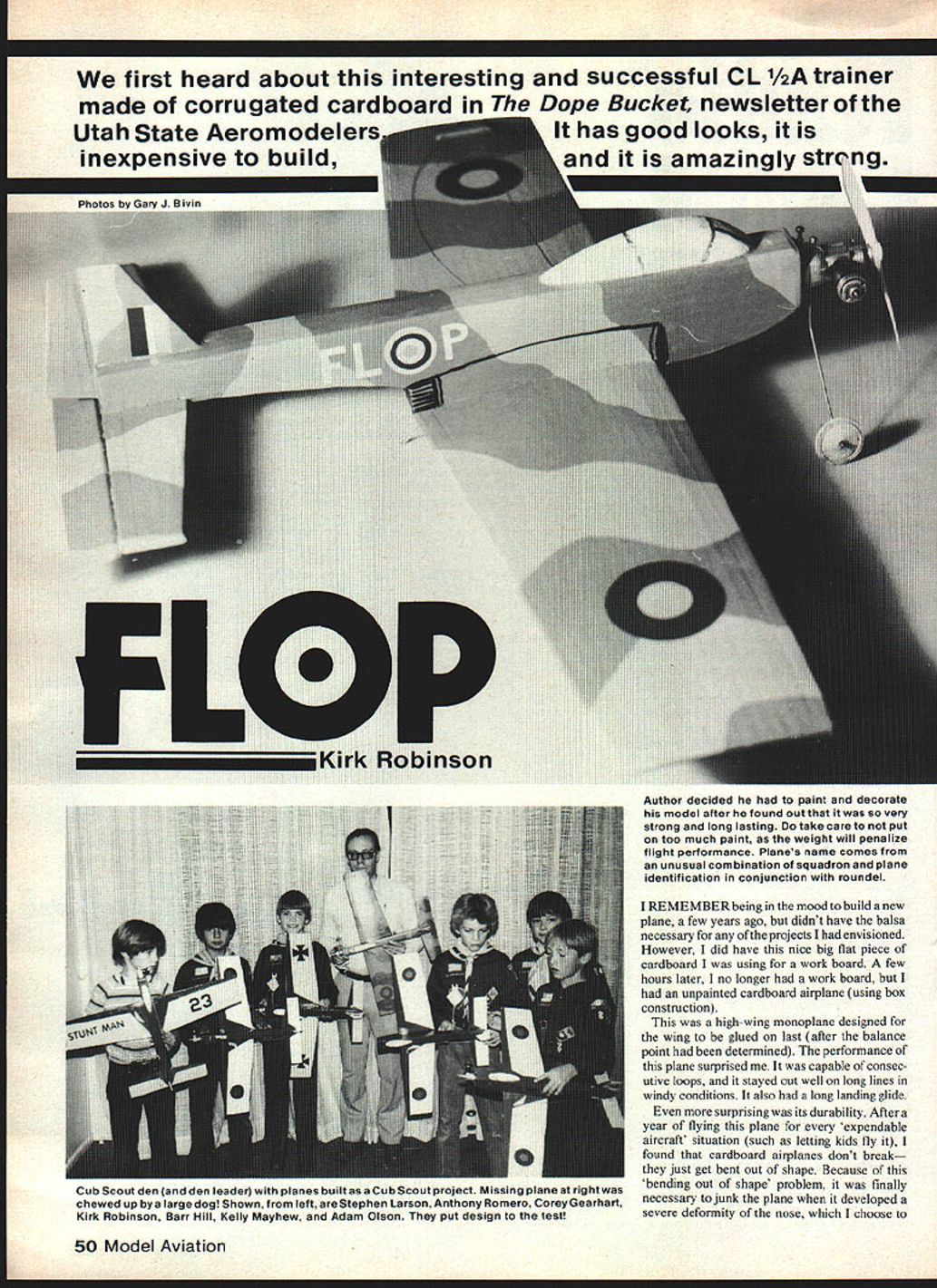
I first heard about this interesting and successful CL 1/2A trainer made of corrugated cardboard in The Dope Bucket, newsletter of the Utah State Aeromodelers. It has good looks, is inexpensive to build, and is amazingly strong. I decided I had to paint and decorate my model after I found out that it was so very strong and long lasting. Do take care not to put on too much paint, as the weight will penalize flight performance. The plane's name comes from an unusual combination of squadron and plane identification letters in conjunction with the roundel.
I remember being in the mood to build a new plane a few years ago but not having the balsa necessary for my envisioned projects. However, I did have a nice big flat piece of cardboard I was using for a work board. A few hours later I no longer had a work board, but I had an unpainted cardboard airplane (using box construction).
This is a high-wing monoplane designed for the wing to be glued on last (after the balance point has been determined). The performance of this plane surprised me: it is capable of consecutive loops, it stays out well on long lines in windy conditions, and it has a long landing glide. Even more surprising was its durability. After a year of using this plane for every "expendable aircraft" situation (such as letting kids fly it), I found that cardboard airplanes don't break — they just get bent out of shape. Eventually the first plane developed a severe deformity of the nose, which I called "the accordion syndrome." I promptly decided to build a replacement that looked more like a full-scale aircraft, was easier to build, and had cardboard doublers to strengthen the nose. After sketching, I came up with the present design, built it, and it flew as well as its predecessor.
About that time I became a Cub Scout den leader, and the plane was put to the test. After a month of den meetings, all the boys had soloed with this new plane. We also put on a flying demonstration for the pack and let various people from the crowd try it (until I ran out of propellers). Successful as this plane was, cardboard doublers were not sufficient to prevent the accordion syndrome indefinitely. Also, in my hurry to get the plane finished, I had only clear-doped it and it kept on lasting and lasting — looking ugly the whole time.
Next spring, with some minor modifications, all the boys in my den were busy building their own cardboard planes. We bought bellcranks, wheels, and wire using den funds, and I donated the paint. After about two months of den meetings, the planes were all finished. Some boys saved to buy engines, and we took them flying. The new planes looked great, flew well, and showed no signs of the annoying nose deformities even after numerous crashes.
The most recent plane took longer to paint and make decals than to build, but I didn't want another plane to last and last while looking ugly. As you may have guessed, the name comes from my choice of squadron and plane identification letters in combination with the roundel.
Overview
- Simple plane built very inexpensively from mostly household materials.
- Extremely durable; almost never breaks even in crashes where it cartwheels wing over wing.
- Can be hand-launched or take off like balsa wood planes.
- Capable of consecutive loops and even inverted flight (though returning to upright from inverted can be somewhat difficult).
- Long, gentle landing glide.
- As a trainer, its main strength is durability. After applying controls, the plane rotates before it starts up or down, giving the novice a little time to think.
- Long (40-ft.) lines can be used to prevent dizziness.
- Main drawback as a trainer: the lifting airfoil (necessary for wing strength) makes it want to climb, and beginners may let it get uncomfortably high on the initial takeoff climb.
Construction
Materials and preparation
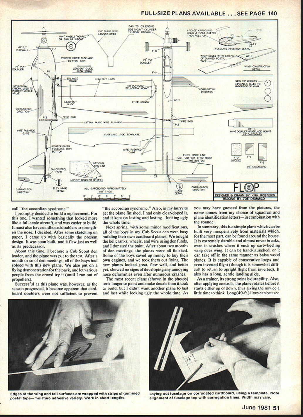
- Cardboard: a good flat piece 28 in. x 6 in. for the wing (corrugations lengthwise). Note: corrugation width varies; adjust measurements to suit your cardboard.
- Poster paper for templates and bottom fuselage pieces.
- Gummed postal tape (moisten-to-stick), about 2 in. wide — cut down the middle for 1 in. strips.
- White glue, 5-min epoxy, 5/8 in. plywood (firewall), 1/8 in. plywood (bellcrank mount).
- Wire (1/16 in. dia.), wheels, bellcrank set (Carl Goldberg 1/2A nylon bellcrank and horn recommended), engine, rubber bands/clamps, sanding block, pizza cutter, razor blade/knife, scissors.
- Optional: styrofoam for canopy, Varathane paints or suitable dope/paints.
Cutting the wing
- Measure and mark the wing shape on cardboard with corrugations lengthwise. Cut out the wing.
- If using a razor blade, ensure it is very sharp at the start. Score the surface on the first stroke, then follow the same path repeatedly, cutting deeper each time. It usually takes about five passes before cutting clear through. Cuts at an angle to corrugations are harder than cuts parallel or perpendicular.
- Imperfect cuts are not critical; you'll improve as you go.
Stabilizer and elevator
- Measure and mark the horizontal stabilizer and elevator with corrugations lengthwise.
- The elevator hinge line on the top must be exactly on a corrugation line; on the bottom it will be midway between two corrugation lines. This alignment is necessary for the elevator hinge to work properly.
- Cut out the stabilizer and elevator as a single piece — do not separate them. Mark the hinge line on the bottom and cut halfway through the cardboard along this bottom hinge line (refer to the plans' elevator hinge detail).
Fin and rudder
- Trace a template for the fin and rudder, then mark and cut it out from cardboard. Corrugations should be straight up and down.
- The hinge line on the left side (looking from tail to nose) should be exactly on a corrugation line; on the right side it should be midway between two corrugation lines. Adhere to this positioning when tracing the template.
- Try to make the cut along the bottom of the fin exactly perpendicular to the surface.
Fuselage
- Trace the fuselage side template from the plan onto poster paper and cut it out.
- The top and sides of the fuselage are a single piece. Top corners (seen from outside) must be exactly on corrugation lines; on the inside these fold lines must be midway between two corrugation lines.
- The width of the fuselage is determined by the cardboard corrugation width. Mine was five corrugations wide (as shown on the plans), but yours may differ. Make sure the fuselage is wide enough for the engine mount.
- Trace the fuselage side shape onto cardboard, lining up the top (flat) part of the template along a corrugation line. Extend the front line perpendicular to the corrugations three inches or so past the fuselage top line. Measure from the top line to the corrugation nearest the desired fuselage width along this line, then use that to trace the other side. Connect tail end lines with a ruler and pencil.
- Cut out the fuselage piece, taking care to make cuts perpendicular to the surface.
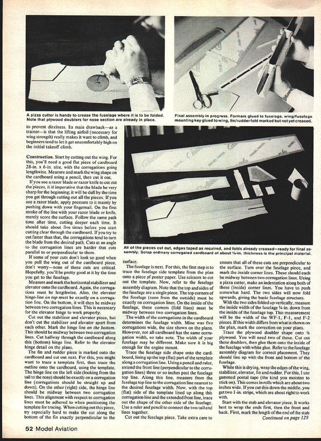
- Turn over the fuselage piece and mark the inside corner fold lines (midway between two corrugation lines). Using a pizza cutter, make an indentation along each inside corner fold line — press fairly hard. Fold the sides upward to create the basic fuselage box.
Doublers and mounting key
- With the two sides folded up, measure the inside width of the fuselage 3/4 in. down from the inside top. This measurement is the width for the WF-1, F-1, and F-2 pieces. If different from the plans, note the correction.
- Trace and cut two plywood doublers from plywood and glue them inside the fuselage with white glue, aligning them with the front and bottom of the fuselage per the assembly diagram.
Wrapping edges (gummed postal tape)
- Cut gummed postal tape down the middle to make 1-in. strips.
- For the stabilizer and elevator: work ends first, then front and back. Mark the length of the end of the stabilizer and elevator on the postal tape roll, cut straight across, then cut down the middle to get two 1-in. strips. Fold each strip lengthwise to make it easier to wrap before the gummed surface dries.
- Moisten a strip thoroughly, stick it on with the edge lined up with the stabilizer fold, fold around the edge, and rub firmly. Repeat for both ends.
- Wrap the leading edges of the stabilizer, then the trailing edge of the elevator. Use overlapping strips if necessary.
- Wrap all edges of the fin and rudder except the bottom edge (where it will glue onto the stabilizer inside the fuselage).
- Wrap all edges of the wing. Do the wing tips before leading and trailing edges. For large pieces, do leading and trailing edges in four pieces with slight overlap.
- None of the fuselage edges are wrapped. After wrapping, check all wrapped edges for looseness; if any are loose, cut open the loose area with a razor blade and glue the tape back down with white glue.
Fuselage formers and wing key
- Measure, mark, and cut fuselage formers F-1 and F-2 and the wing/fuselage mounting key WF-1 from cardboard; ensure their widths match the inside fuselage width. Corrugations on these pieces are width-wise.
- Fold the fuselage to shape and glue in the two fuselage formers with white glue. Hold with rubber bands or clamps while drying. Before glue fully cures, check front and back and square the corners. The front former is recessed 1/8 in. below the wing cutout to make room for the WF-1 key.
- Carefully bend the wing to fit the wing cutout in the fuselage; minor wrinkles on the bottom of the wing are not a problem.
- Ensure WF-1 fits inside the wing cutout; sand if necessary. Mark the lengthwise center line on the top of WF-1 and the chord-wise center line on the top of the wing. Glue WF-1 to the top of the wing using these center lines for alignment. WF-1 lines up flush with the leading edge but is short of the trailing edge by 3/8 in.
Rudder and elevator hinge detail
- While WF-1 is drying, mark the fin/rudder hinge line on the right side (looking from the back to the front) of the fin and rudder piece; this line should be midway between two corrugation lines. Make an indentation along this line with a pizza cutter and carefully bend the rudder to the right to the angle shown on the plan top view.
- On the stabilizer/elevator piece: turn it upside down and, using a razor blade or knife, cut through the edge-wrapping on the bottom surface to extend the hinge line to the end of the elevator. Do both ends. Run a medium-dull pencil up and down the elevator hinge cut to enlarge it a bit so the elevator bends up and down easily.
Fuselage slots and final joins
- Measure and mark the rudder slot in the fuselage. Make the front of the slot by poking the tip of a razor knife through, then cut the sides with scissors.
- Examine the stabilizer cutout on the fuselage. If the fuselage sides don't fit flat and tight onto the stabilizer, true them up with a sanding block or file.
- Glue the wing onto the fuselage with white glue. Lay the fuselage upside down and put weights on the center of the wing to hold it firmly while drying. Glue the stabilizer onto the fuselage (note that the side visible while fuselage is upside down is the bottom — the side with the hinge cut).
- When wing and stabilizer joints are dry, turn the plane over and glue in the fin and rudder, ensuring it is glued into the slot and down against the stabilizer.
- Trace the shape of the front of the fuselage onto 5/8 in. plywood and cut out the firewall. Glue the firewall onto the front of the fuselage with 5-min epoxy and clamp or hold until it hardens.
- Hold poster paper up against the fuselage bottom and trace the two fuselage bottom pieces (note overlapping onto the wing at the front piece and onto the stabilizer at the back piece). Cut and glue these onto the fuselage bottom. Cut small rectangular pieces of poster paper to fill the holes on either side of the fin and glue them in place.
- Cut strips of postal tape to wrap around the corners of the fuselage sides and the F-2 former.
Canopy
- If protecting a needle valve that sticks above the top of the fuselage, add a canopy.
- Simple cardboard canopy: trace two to four side-view pieces from cardboard, laminate them together, glue a piece of poster paper over the top, and glue to the fuselage.
- Styrofoam canopy: trace the side view onto foam, cut with a hot-wire or coping saw, mark the center line along the top and trace the top view shape onto the bottom, then shape with a file or coarse sandpaper, finishing with medium grit sandpaper.
- If painting with paints that do not attack foam, glue the styrofoam canopy down with white glue. If paint might attack foam, glue the canopy on after painting with a silicone sealer or another non-attacking adhesive, or leave the canopy area unpainted and glue it on later with white glue.
Bellcrank mount and lead-outs
- Trace the bellcrank mount shape onto 1/8 in. plywood, cut it out, make the hole for the bellcrank wood screw, and glue the mount onto the top of the left wing in the position shown on the plan. Measure carefully for correct positioning.
- Make the lead-out guide for the flying lines from a popsicle stick or similar scrap and glue it in place on top of the left wing at the position shown on the plan.
Painting tips
- If using dope: apply two coats of clear dope before the color coat (three coats of clear for postal tape edge-wrapping). Sand with fine sandpaper between coats.
- If using polyurethane paint: you can start with the color; it will probably take three coats with sanding between coats.
- If you don't live near a hobby shop, Varathane plastic paints work well and resist fuel. The author's plane is finished with a coat of Varathane clear satin finish.
Remaining details
- If the canopy wasn't glued earlier, glue it on now after the paint has dried. Mark canopy frame lines with a marking pen.
- Cut and bend 1/16-in. dia. wire for pushrod, landing gear, and the wire skid. Poke the skid up through the wing into the right fuselage side at the shown angle and glue it in with epoxy.
- Install the bellcrank, pushrod, and elevator horn. The Carl Goldberg 1/2A nylon bellcrank and horn set is recommended.
- Flex the elevator up and down several times to loosen it after painting. If the pushrod bows too much when applying up control, bend a pushrod guide out of 1/16-in. wire and glue it in place (not always necessary).
- Attach wheels to the wire landing gear with a glob of 5-min epoxy and a paper washer.
- Mark engine mounting screw positions, make the screw holes (wood screws recommended), and install the engine. Before tightening, slide in the landing gear wire, then tighten the engine mount.
- Install the lead-outs.
Flying tips
- For most conditions, use 35-ft. wire lines of .008-in. dia.
- On takeoff, avoid giving the plane up-control: it will rise by itself when it reaches flying speed because of the lifting airfoil.
- When the engine stops, expect a long, gentle landing glide — provided you don't try to keep climbing.
- If nervous, let the plane bash into the ground a time or two, pick it up, dust it off, restart the engine, and try again.
Transcribed from original scans by AI. Minor OCR errors may remain.

