
FLYING ACES STICK
by Roland Schmidt
Fly Electric!
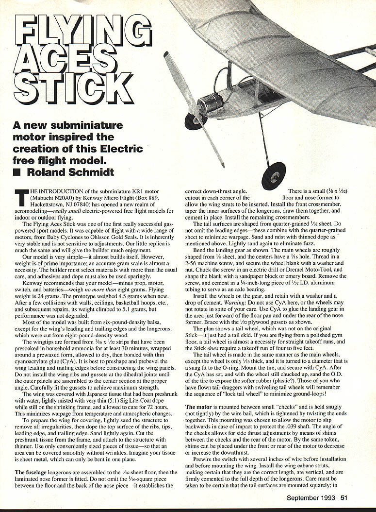
The introduction of the subminiature KR1 motor (Mabuchi N20A0) by Kenway Micro Flight (Box 889, Hackettstown, NJ 07840) has opened a new realm in aeromodeling — really small electric-powered free-flight models for indoor and outdoor flying. The Flying Aces Stick is a small replica of one of the first successful gas-powered sport models. It is inherently very stable, not sensitive to fine adjustments, and is simple to build — but weight is critical.
Summary / Specifications
- Type: FF Electric Sport
- Wingspan: 15½ inches
- Engine size/type: KR1 subminiature (Mabuchi N20A0)
- Flying weight: 24 grams
- Recommended empty weight (minus prop, motor, switch, batteries): ≤ 8 grams
- Construction: Built-up
- Covering/finish: Japanese tissue and Sig Lite-Coat dope
Materials and Weight
Most of the model was built from six-pound-density balsa, except the wing leading and trailing edges and the longerons, which were cut from eight-pound-density wood. An accurate gram scale is strongly recommended. Adhesives and dope should be used sparingly.
Kenway recommends the completed airframe (without prop, motor, switch, batteries) weigh no more than eight grams; flying weight should be about 24 grams. The prototype weighed 45 grams new and rose to 51 grams after repairs, with little performance degradation.
Construction
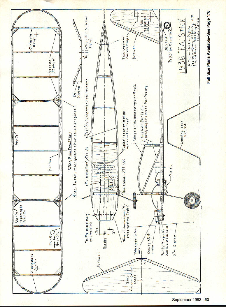
Wing
- Preshape and prebevel the wing leading and trailing edges before constructing the wing panels.
- Wing tips: use 1/16 x 1/32 strips presoaked in household ammonia for at least 30 minutes, wrapped around a pre-waxed form, allowed to dry, then bonded with thin cyanoacrylate (CyA) glue.
- Do not install the wing ribs and gussets at the dihedral joints until the outer panels are assembled to the center section at the proper angle. Carefully fit gussets for maximum strength.
Covering:
- Preshrink Japanese tissue with water on a shrinking frame.
- While still on the frame, lightly mist with very thin Sig Lite-Coat dope and allow to cure for 72 hours to minimize warpage from temperature and humidity changes.
- To prepare the wing: lightly sand the structure to remove irregularities, then dope the top surface of the ribs, tips, leading edge, and trailing edge. Sand lightly again.
- Cut the preshrunk tissue into conveniently sized pieces (cover each area smoothly without wrinkles) and attach to the structure with thinner. Imagine the tissue as sheet metal that can only be bent in one plane.
Fuselage
- Assemble the fuselage longerons to the 1/16-sheet floor, then fit the laminated nose former.
- Do not omit the 1/16-square piece between the floor and the back of the nose piece — it establishes the correct down-thrust angle.
- A small 1/8 x 1/32 cutout in each corner of the floor allows the wing struts to be inserted.
- Install the front crossmember, taper the inner surfaces of the longerons, draw them together, and cement in place. Install remaining crossmembers.
Tail Surfaces
- Shape tail surfaces from quarter-grained 1/32 sheet.
- Do not omit the leading edges — combined with quarter-grained sheet they help minimize warpage.
- Sand, mist with thinned dope as described above, then lightly sand again to remove fuzz.
Landing Gear and Wheels
- Bend the landing gear as shown on the plan.
- Main wheels: roughly shape from 1/8" sheet; centers have a 1/16" hole.
- Thread a 2-56 machine screw through the wheel blank and secure with a washer and nut. Chuck the screw in an electric drill or Dremel Moto-Tool and shape the blank with a sandpaper block or emery board.
- Remove the screw and cement in a 1/4-inch-long piece of 1/32" I.D. aluminum tubing to serve as an axle bearing.
- Install wheels on the gear and retain with a washer and a drop of cement. Warning: Do not use CyA on the axle or the wheels may seize and not rotate.
- Use CyA to glue the landing gear in the area just forward of the floor pan and under the rear of the nose former. Brace with 1/32" plywood gussets as shown on the plan.
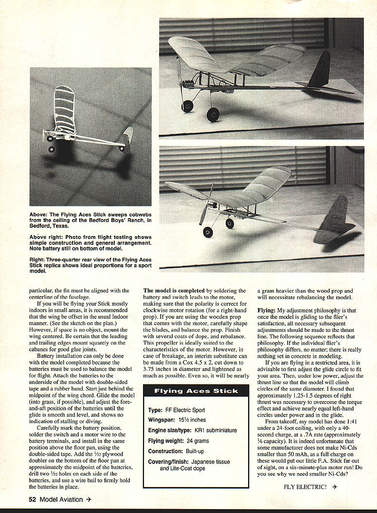
Tail wheel:
- The original Stick had a skid; the plan shows a tail wheel. For polished gym floors a tail wheel is recommended to achieve straight takeoff runs.
- Make the tail wheel like the main wheels, except the wheel is only 1/32" thick and turned to a diameter that is a snug fit to the O-ring tire.
- Mount the tire and secure with CyA. After the CyA has set, with the wheel still chucked, sand the outer diameter of the tire to expose softer rubber for better traction.
- Note: locking the tail wheel can help minimize ground loops during takeoff.
Motor Mounting and Controls
- Motor is mounted between small "cheeks" and held snug (not tight) by a wire bail, the ends of which are twisted together.
- This mounting allows the motor to slip backward in case of impact to protect the 0.039-inch shaft.
- The angle of the cheeks allows side-thrust adjustments by inserting shims between the cheeks and the rear of the motor. Shims under the front or rear of the motor change downthrust.
- Prewire the switch with several inches of wire before installation and before mounting the wing.
- Install the wing cabane struts, ensuring they are the correct length, vertical, and firmly cemented to the full depth of the longerons.
- Be certain tail surfaces are mounted squarely; in particular, align the fin with the fuselage centerline.
Wing Mounting and Offset
- If flying mostly indoors in small areas, offset the wing in the usual indoor manner (see plan). If space is not a problem, mount the wing centered.
- Ensure the leading and trailing edges seat squarely on the cabanes for good glue joints.
Batteries, Balance, and Final Assembly
- Battery installation should be done after the model is completed because batteries are used to balance the model.
- Attach the batteries to the underside of the model with double-sided tape and a rubber band, starting just behind the midpoint of the wing chord.
- Glide the model (into grass if possible) and adjust the fore-and-aft battery position until the glide is smooth, level, and shows no tendency to stall or dive.
- Carefully mark the battery position. Solder the switch and a motor wire to the battery terminals and install the battery in the same position above the floor pan using double-sided tape.
- Add a 1/32" plywood doubler on the bottom of the floor pan at approximately the midpoint of the batteries. Drill two 1/32" holes on each side of the batteries and use a wire bail to firmly hold the batteries in place.
- Complete wiring by soldering the battery and switch leads to the motor, making sure polarity produces clockwise motor rotation for a right-hand prop.
Propeller:
- If using the wooden prop supplied with the motor, carefully shape and balance the blades. Finish the model with several coats of dope and rebalance.
- An interim substitute prop, if needed, can be made from a Cox 4.5 x 2 prop cut down to 3.75 inches and lightened as much as possible. Expect it to be nearly a gram heavier than the wood prop and to require rebalancing.
Flying and Trim
- Adjustment philosophy: once the glide is satisfactory, make subsequent adjustments to the thrust line rather than to airframe incidence.
- If flying in a restricted area, first adjust the glide circle to fit the space. Then, under low power, adjust the thrust line so powered climb circles match glide circles.
- The author found approximately 1.25–1.5 degrees of right thrust was necessary to achieve nearly equal left-hand circles under power and in the glide.
Performance note:
- The author's model achieved 1 minute 41 seconds flight time under a 24-foot ceiling with only a 40-second charge at about 0.7 amp rate (approximately 1/6 capacity).
- Comment: smaller Ni-Cad cells (less than 50 mAh) would enable much longer flights and are desirable for these subminiature models.
Final Remarks
The Flying Aces Stick is simple and forgiving but demands careful material selection and strict attention to weight. With proper construction, covering, balance, and thrust-line trimming, it provides enjoyable free-flight performance both indoors and outdoors. Fly electric!
Transcribed from original scans by AI. Minor OCR errors may remain.

