
FLYING FLAG
Fran McElwee
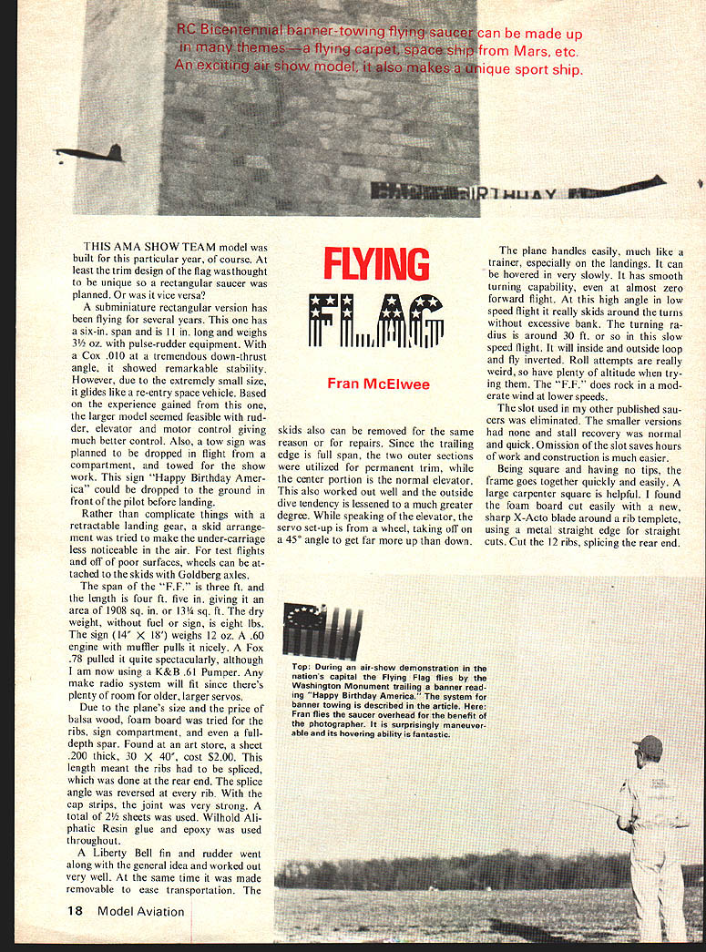
THIS AMA SHOW TEAM model was built for this particular year, of course. At least the trim design of the flag was thought to be unique so a rectangular saucer was planned. Or was it vice versa?
A subminiature rectangular version has been flying for several years. This one has a six-in. span and is 11 in. long and weighs 3½ oz. with pulse-rudder equipment. With a Cox .010 at a tremendous down-thrust angle, it showed remarkable stability. However, due to the extremely small size, it glides like a re-entry space vehicle. Based on the experience gained from this one, the larger model seemed feasible with rudder, elevator and motor control giving much better control. Also, a tow sign was planned to be dropped in flight from a compartment, and towed for the show work. This sign "Happy Birthday America" could be dropped to the ground in front of the pilot before landing.
Rather than complicate things with a retractable landing gear, a skid arrangement was tried to make the undercarriage less noticeable in the air. For test flights and off of poor surfaces, wheels can be attached to the skids with Goldberg axles.
The span of the "F.F." is three ft.; the length is four ft. five in., giving it an area of 1,908 sq. in. or 13¼ sq. ft. The dry weight, without fuel or sign, is eight lbs. The sign (14" x 18") weighs 12 oz. A .60 engine with muffler pulls it nicely. A Fox .78 pulled it quite spectacularly, although I am now using a K&B .61 Pumper. Any make radio system will fit since there's plenty of room for older, larger servos.
Due to the plane's size and the price of balsa wood, foam board was tried for the ribs, sign compartment, and even a full-depth spar. Found at an art store, a sheet .200 thick, 30 x 40, cost $2.00. This length meant the ribs had to be spliced, which was done at the rear end. The splice angle was reversed at every rib. With the cap strips, the joint was very strong. A total of 2½ sheets was used. Wilhold Aliphatic Resin glue and epoxy was used throughout.
A Liberty Bell fin and rudder went along with the general idea and worked out very well. At the same time it was made removable to ease transportation. The skids also can be removed for the same reason or for repairs. Since the trailing edge is full span, the two outer sections were utilized for permanent trim, while the center portion is the normal elevator. This also worked out well and the outside dive tendency is lessened to a much greater degree. While speaking of the elevator, the servo set-up is from a wheel, taking off on a 45° angle to get far more up than down.
The plane handles easily, much like a trainer, especially on the landings. It can be hovered in very slowly. It has smooth turning capability, even at almost zero forward flight. At this high angle in low speed flight it really skids around the turns without excessive bank. The turning radius is around 30 ft. or so in this slow speed flight. It will inside and outside loop and fly inverted. Roll attempts are really weird, so have plenty of altitude when trying them. The "F.F." does rock in a moderate wind at lower speeds.
The slot used in my other published saucers was eliminated. The smaller versions had none and stall recovery was normal and quick. Omission of the slot saves hours of work and construction is much easier.
Being square and having no tips, the frame goes together quickly and easily. A large carpenter square is helpful. I found the foam board cut easily with a new, sharp X-Acto blade around a rib template, using a metal straight edge for straight cuts. Cut the 12 ribs, splicing the rear end.
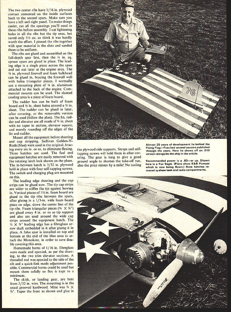
Two center ribs have 1/16" plywood contact-cemented inside the surfaces back of the second spars. Make sure you have left and right panels marked to make things easier. Cut the openings you'll need in the ribs before assembly. Cut lightening holes; the tip ones saved 5 oz., but I think hardly worth the effort. Pin the ribs together, sand the spar material slots for uniform ribs, glue and assemble the full-depth spar first. Spruce spars are glued in place. The leading edge is a single piece across the span; cut out the engine area later. A plywood firewall and foam bulkhead can be glued in, bracing the firewall with balsa triangular pieces. Normally I use a mounting plate of 1/4" aluminum attached to the back of the engine. Commercial mounts can be used. A slanted cooling area piece of foam board is used.
The rudder box can be built of foam board with balsa around the top; the rudder can be glued later after covering. A removable version can be used — follow the plan. The fin, rudder and elevator are made with no taper; the elevator is square, merely rounding off the edges of the fin and rudder. Mount equipment before sheeting. Cap strips and Sullivan Golden Rods were used in the original bracing to eliminate flexing.
Three hatches are used for fuel and equipment; hatches are easily removed. A rotating latch lock is shown on the plans. The in-between hatch is 3/32" plywood held in place with four self-tapping screws. The switch and charging plug are mounted on this.
The leading edge sheeting and the cap strips can be glued now. The tip cap strips are wider to stiffen the tip against bowing in. Vertical pieces of 1/2 in. foam board are glued to the tip ribs between the spars, after gluing in a 1/3-in. wide foam board piece on edge down the center line of the tip ribs. Foam triangular pieces (3/8 x 3/4") are glued every 4 in. or so as tip support and also are used around the wide cap strips around the equipment hatch. The 1/2 x 3/4" leading edge has a fiberglass arrow shaft embedded in it after gluing it in place. A false spar is installed on top and bottom at the end of the blue area to attach the Monokote, in order to save double covering this area.
Homemade horns of 1/16 in. fiberglass were made and epoxied, as per the drawing, to the two trim elevator sections. A threaded rod was epoxied to the side of the rib and a quick-link made adjustment possible. Commercial horns could be used but mount them solidly so flex is kept to a minimum.
The skids, or landing gear, are bent from 5/32 in. wire. The mounting is in the usual grooved hardwood. Mine was 3/8 x 3/4". Taper the front as shown and glue in the plywood side supports. Straps and self-tapping screws will hold them in after covering. The gear is long to give a good ground angle to shorten the take-off run; also the prop misses by a mile! No taxiing.
Flying Flag
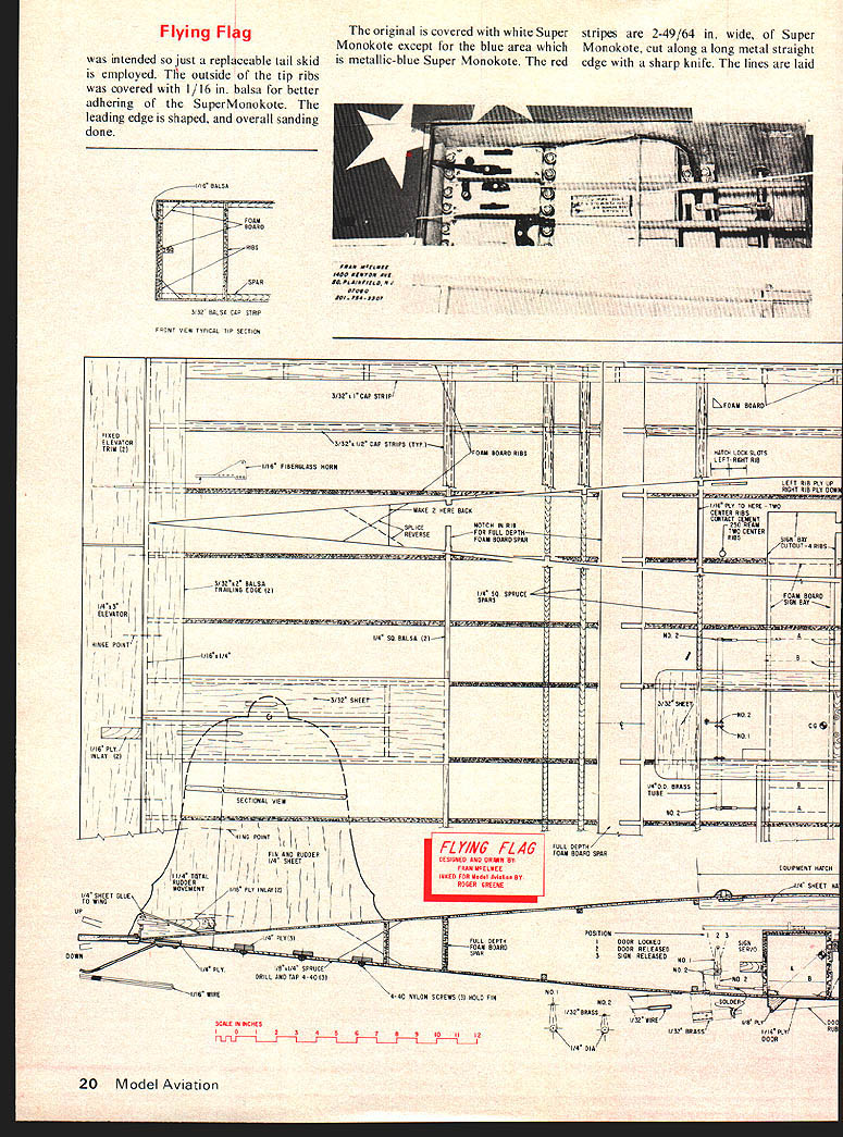
was intended so just a replaceable tail skid was employed. The outside of the tip ribs was covered with 1/16 in. balsa for better adhering of the SuperMonokote. The leading edge is shaped, and overall sanding done.
The original is covered with white Super-Monokote except for the blue area which is metallic-blue Super Monokote. The red stripes are 2-49/64 in. wide, of Super Monokote, cut along a long metal straight edge with a sharp knife. The lines are laid.
Two center ribs have 1/16 in. plywood contact cemented inside surfaces back of the second spars. Make sure you have left and right panels — this makes things easier. Cut openings you'll need in the ribs before assembly. Cut lightening holes; the tip ones saved 5 oz., though I think hardly worth the effort. Pin ribs together, sand spar material slots uniform. Glue ribs; assemble full‑depth spar first. Spruce spars are glued in place. The leading edge is one single piece across the span; cut out later for the engine area.
The plywood firewall and foam bulkhead can be glued, bracing the firewall well with balsa triangular pieces. I normally use a mounting plate of 1/4 in. aluminum attached to the back of the engine. Commercial mounts can be used. The slanted cooling area is a piece of foam board. The rudder box can be built of foam board and balsa around the rudder; it can be glued later after covering. A removable version can be used — follow the plan. The fin, rudder and elevator are made with no taper section; the elevator is square, merely rounding off the edges of the fin and rudder.
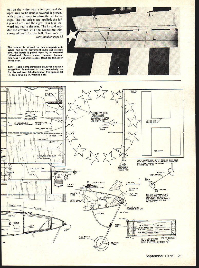
Mount equipment before sheeting. Cap strips (Sullivan Golden‑N‑Rods) were used originally as bracing to eliminate flexing. Three hatches are used; the fuel and equipment hatches are easily removed. A rotating latch lock is shown on the plans. The in‑between hatch is 3/32 in. plywood held in place with four self‑tapping screws. The banner is stowed in this compartment. When half‑servo movement pulls out release pins, the hatch is pulled open by an external rubberband. Bands shown beneath banner help toss it out after release. Band‑loaded cover snaps back.
Left: Radio compartment is snug yet is readily accessible. Foamboard is used extensively, as for ribs and even full‑depth spar. The span is 53 in., area 1908 sq. in. Weight, 8 lbs.
Transcribed from original scans by AI. Minor OCR errors may remain.

