


Flying For Fun
Dr. D. B. Mathews
OOPS! The one expression that should never be used by a physician or dentist during a procedure is "OOPS"! In a non-clinical setting, however, it is permissible, and the term certainly applies at least twice to recent columns. So let's set the record straight:
The Cessna AW-1 R.C.S.D. model pictured in the August 1991 column was based on a published design by Jim Adams, but the beautiful version shown is the handiwork of Walt Geary of Absecon, New Jersey.
And then there is the "Jeep" thing from the October 1991 copy. That miscue certainly illustrates the adage that first the memory goes. The Jeep cartoon character appeared in Popeye, not Alley Oop. A surprising number of readers wrote to set that mistake straight. Seems the military referred to the small four-wheel-drive vehicle as a General Purpose unit, or to abbreviate in the military fashion, a GP. Obviously the GIs, not Willys Motor, altered that to Jeep.
Art Chester obviously was a Popeye fan, calling racing aircraft names like "Sweetpea," "Goon" and "Jeep" — all characters in the cartoon strip.
Bill Dahlgren wrote to advise me about another aircraft nicknamed after a character in the Thimble Theatre/Popeye strip. Bill says, "...also in that strip was a portly hamburger-addicted freeloader ('I'll gladly pay you on Wednesday for a hamburger today') named J. Wellington Wimpy. Combining the rotund appearance of both man and plane with name string may well explain why the British airmen of the period nicknamed the Vickers Wellington bomber 'Wimpy.' A rather clever multiple pun indeed." (Thanks, Bill, the MA Editorial staff loved this one!)
Les Long of Washington State also developed a neat little low-winged homebuilt which he named "Wimpy." Can't help wondering if there are other aircraft named after cartoon strip characters. Anyone think of others?
EATING HUMBLE PIE
Only a madman or someone with a monstrous ego would attempt to develop another trainer! I seem to suffer from both maladies, but the project has certainly deflated my ego, so what does that leave?
Apparently I was one of the first (MA July 1975) to suggest that the Free Flight designs of the 1930s made excellent trainers when RC was added. Several manufacturers have proven the concept with trainers designed around Old Timer parameters, i.e., light wing loadings, low power, large size, inherent stability, and high-lift airfoils.
Unfortunately, no virtue is obtained without some compromise. Let's be candid here. Stick-and-strip construction as used on Old Timers and their contemporary clones is inherently difficult to build accurately and leaves a lot to be desired in reparability after those inevitable mishaps associated with learning to fly RC.
High-lift wing airfoils, either undercambered or true flat-bottomed, do not lend themselves well to wide airspeed fluctuations and are invariably rather twitchy in windy weather.
Additionally, the light wing loadings, large-ish empennages, and wide fuselage profiles contribute to serious problems when flying in even moderate winds. Anyone who has flown a lightly loaded flat-bottomed wing setup has become painfully aware what a handful such a model can be in winds much over 10 mph. Simply put, they jump wildly side to side, up and down, with maddeningly wide trim changes necessary between up-wind and down-wind, and also each time the throttle speed is varied. It's the nature of the flat-bottomed-airfoil beast.
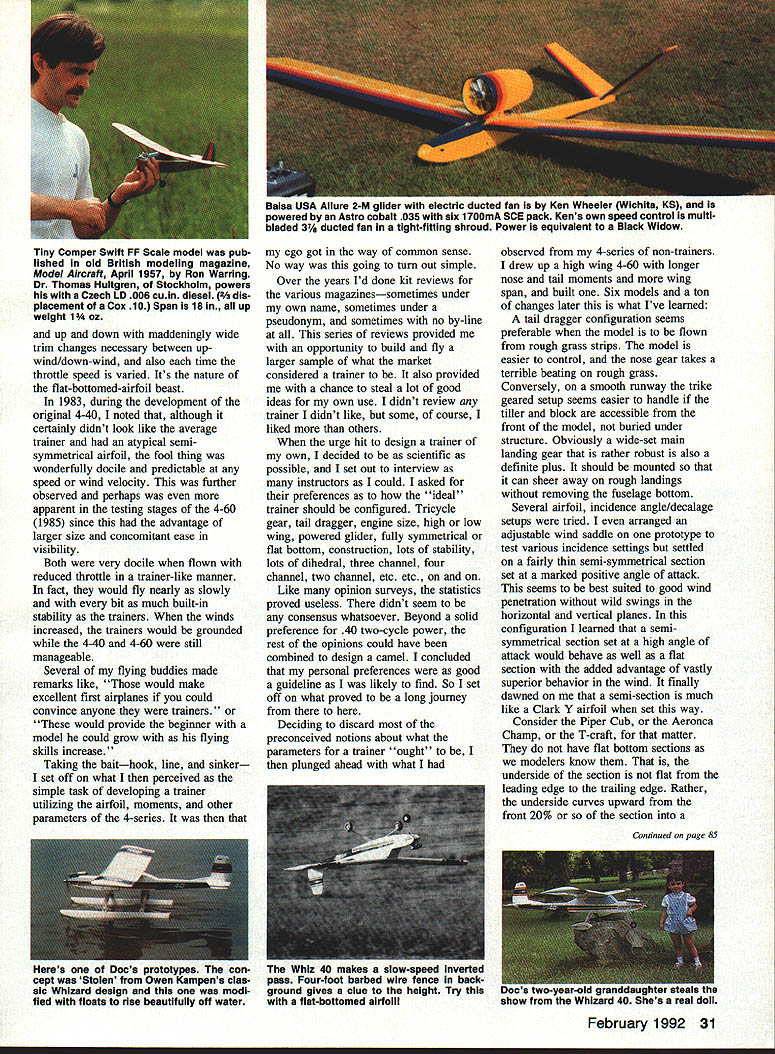
In 1983, during the development of the original 4-40, I noted that, although it certainly didn't look like the average trainer and had an atypical semi-symmetrical airfoil, that fool thing was wonderfully docile and predictable at any speed or wind velocity. This was further observed — and perhaps even more apparent — in the testing stages of the 4-60 (1985), since this had the advantage of larger size and concomitant ease in visibility.
Both were very docile when flown with reduced throttle in a trainer-like manner. In fact, they would fly nearly as slowly and with every bit as much built-in stability as the trainers. When the winds increased, the trainers would be grounded while the 4-40 and 4-60 were still manageable.
Several of my flying buddies made remarks like, "Those would make excellent first airplanes if you could convince anyone they were trainers," or "These would provide the beginner with a model he could grow with as his flying skills increase."
Taking the bait — hook, line, and sinker — I set off on what I then perceived as the simple task of developing a trainer utilizing the airfoil, moments, and other parameters of the 4-series. It was then that my ego got in the way of common sense. No way was this going to turn out simple.
Over the years I'd done kit reviews for the various magazines—sometimes under my own name, sometimes under a pseudonym, and sometimes with no by-line at all. This series of reviews provided me with an opportunity to build and fly a large sample of what the market considered a trainer to be. It also provided me with a chance to borrow a lot of good ideas for my own use. I didn't review any trainer I didn't like, but some, of course, I liked more than others.
When the urge hit to design a trainer of my own, I decided to be as scientific as possible, and I set out to interview as many instructors as I could. I asked for their preferences as to how the "ideal" trainer should be configured, including:
- Tricycle gear or taildragger
- Engine size
- High wing or low wing
- Powered glider
- Fully symmetrical or flat-bottom construction
- Lots of stability or less stability
- Lots of dihedral or less dihedral
- Two, three, or four channels
Like many opinion surveys, the statistics proved useless. There didn't seem to be any consensus whatsoever. Beyond a solid preference for a .40 two-cycle power, the rest of the opinions could have been combined to design a camel. I concluded that my personal preferences were a good guideline as I was likely to find. So I set off on what proved to be a long journey from there to here.
Deciding to discard most preconceived notions about what the parameters for a trainer "ought" to be, I then plunged ahead with what I had observed from many sections of non-trainers. I drew up a high-wing 4-60 with a longer nose and tail moments and more wingspan, and built one. Six models and a ton of changes later this is what I've learned:
A tail-heavy configuration seems preferable for a model to be flown from rough grass strips. The model is easier to control, and the nose gear takes a terrible beating on rough grass. Conversely, on a smooth runway the trike-geared setup seems easier to handle if the tiller and block are accessible from the front of the model, not buried under the structure. Obviously a wide-set main landing gear that is rather robust is also a definite plus. It should be mounted so that it can shear away on rough landings without removing the fuselage bottom.
Several airfoil and incidence-angle setups were tried. I even arranged an adjustable wedge under the engine mount to test various incidence settings but settled on a fairly thin semi-symmetrical section set at a marked positive angle of attack. This seems best suited to good wind penetration without wild swings in the horizontal and vertical planes. In this configuration I learned that a semi-symmetrical section set at a high angle of attack would behave as well as a flat section with the added advantage of vastly superior behavior in the wind. It finally dawned on me that a semi-symmetrical section set this way is much like a Clark Y airfoil.
A Clark Y has the leading edge above the trailing edge when a datum line is drawn. In other words, a Clark Y section is not what we would call truly flat-bottomed. There is a very important difference!
Generous amounts of downthrust combined with a couple of degrees of right thrust seemed to lock the model's flight straight ahead regardless of the throttle setting. I also learned that trim is strongly affected by prop diameter and pitch and concluded that the thrust offsets have to be tailored to the prop or vice versa. Therefore beam mounts don't quite do it. It is much easier to fine-tune thrust settings if the engine is mounted to the firewall so that shims can be used.
A light but strong wing of about 800 in^2 was found to be ideal if the loading could be kept in the 10 to 12 oz/ft^2 range. Use of spruce spars and shear webs (which also serve as the jigs for rib setting) and an airfoil that could be built flat from the main spar to the trailing edge made construction rather simple. Elimination of cap strips and sheeted leading edges certainly eliminated a lot of tedious work, as well. This construction technique has evolved over several years and is good enough that it is being copied by other designers. I find that flattering.
After six prototypes and several construction methods for the fuselage I settled on the classic crutch construction. This I borrowed from Owen Kampen's classic Whizard design. Combining his technique with light ply tab-in-slot construction enables a builder to create a fuselage that is unfailingly true and square. The crutch is placed upside-down over the top view, the bulkheads and sides are aligned to it, then the bottom is added and the whole shebang is stuck together with cyanoacrylate. The resulting box is removed and the cabin/wing-saddle box is assembled onto it. A removable tank hatch (an absolute must in my opinion) is punched out of the crutch, as are two temporary cutouts under the wing saddle to create a radio compartment. Only an incredible klutz could build this fuselage crooked!
Once I had justified borrowing Kampen's construction technique I felt a whole lot less guilty about configuring my Whiz to resemble a much larger Whizard. By keeping things thin and light behind the wing and longish in front I was able to develop a fuselage with unusually long moments to dampen wind- and control-induced yaw and pitch without requiring ballast to balance. To help with equipment installation and service I found that an extra-wide fuselage looked fine with the longish fuselage. Even the largest of servos can be mounted side by side to greatly simplify installation.
I tried a prototype with increased dihedral and no ailerons and again was humbled. Years ago I wrote a product review of what has become a classic trainer, building two of them as a matter of fact—one with ailerons and the other with the alternate high dihedral and no ailerons. I felt that the three-channel version was superior as it was definitely more stable with stronger surf correction while recovering from turns and so forth.
That particular design uses a very sharp entry at the leading edge of a true flat-bottomed airfoil. Apparently to control the airfoil, the design also incorporates 5° or 6° of positive incidence in the stab setup. In winds, however, the design pitched badly, and the high dihedral caused some roll-axis problems as well.
Conversely, the Whiz project has proven much better in a moderate dihedral/aileron configuration. Ailerons also add the virtue of being able to pick up the down wing if a gust of wind hits the model on final. So much for my long-held opinion that ailerons don't belong on trainers.
Configuring the empennage proved to be an enlightening experience as well. Vertical and horizontal stab volumes are dictated by wing area and span and the length of the fuselage moments; everyone knows that. I found that if the volume is excessive the model will wind-vane badly and/or be subject to pitch-axis problems in the wind. Conversely, too little empennage volume adversely affects stability, particularly in slow flight.
Disdaining mathematical formulas, I set out to find by trial and error just how much was enough. I actually rigged a prototype with strap-on stab and fin tips and proceeded to fly with various sizes. I learned several things. We tend to design our models with more than enough horizontal stab and the shape is almost as important as the size.
As an example: a tall narrow vertical stab combined with a dorsal fin provides turns with less tendency to tighten up and spiral than a short stubby unit. Don't exactly know why, but that's what I discovered. So — five years and six prototypes later, with lots of messing around and modifications, what did I end up with? A trainer that is totally different from my original conception.
As I said up front, one ego must be dealt with lest it get in the way of admitting, "I don't know." I'm not at all sure I know—even now—but I have found lots of things that certainly have increased my fund of knowledge. The Whiz is no more inherently stable than any other trainer I know of, it builds no easier than another I've built, it is no more sturdy or repairable than another, and isn't a great deal more easily maintained than another. The only thing is that this is a single design that comes awfully close to matching the best virtues of those other trainer designs in one package.
The Whiz is definitely easier to taxi, take off, fly, and land in winds above 10 mph than any other trainer I've flown. For those of you who are learning to fly and encountering the frustrations of trying to coordinate instructor's time, your time, and the wind, this is a tremendous advantage.
The final configuration can be trimmed to fly hands-off with the transmitter on the ground if you're brave. It will land itself in low throttle after the final approach has been set up. Yet with the throttle open and in the hands of an experienced pilot the Whiz can do consecutive inside and outside loops, nice axial rolls, well-controlled Cuban 8s and the most extraordinary walking-speed low-level inverted passes I've ever witnessed. And those are virtues peculiar to this project, believe me.
I've been asked several times to present programs to local clubs explaining how one goes about designing a model airplane. This seemed an appropriate time to relate to you readers what the process can be like. Please note that I studiously avoid long-winded technical dissertations with all sorts of fancy mathematical formulas, airfoil numbers and such. Why? Because I frankly have never understood them, and feel the real proof of any model airplane design is not theoretical dogma, but plain old flying performance. The proof of the pudding is in the eating, and the proof of the design is in the flying.
So do I think I've developed the "perfect" trainer? No, I don't. Considering the wide variances in beginners' hand and eye coordination, reflex rates, visual acuity, personalities and the skills of their instructors, there really isn't such a thing as a "perfect" trainer—one size fits all.
However, the Whiz is more versatile than any other I know of. I am extremely proud of the project and hope the effort has been worthwhile. Lord knows I'll never let myself get caught in the ego/madness complex again.
CLOSING THE GAP
Like almost everyone, I've known for years about the advantages of sealed surface gaps on model airplanes. On occasion I've sealed the space between trailing edges and ailerons etc. with Scotch Magic Tape or attempted to iron heat-shrink on top of heat-shrink. While this arrangement works, I've also been unsatisfied with the gooey mess that builds up on the interface as fuel and oil creep between the covering and the sealing tape.
John Walker of Wichita recently built me a 4-120 biplane converted into an Ultimate look-alike sort of thing. The first thing that caught my attention when he delivered it was that he had sealed the surfaces in one piece of MonoKote. After more carefully looking at his fleet of models, I found that he has been doing this for several years and I'd never really noticed. Maybe everyone does this, but it was new to me.
John cuts a section of covering the size of the area to be covered, seals the borders of the wing, etc., leaving the movable surface unattached until he flexes the surface. He then seals in the gap, attaches the covering to the movable surface, and uses a heat gun to shrink the covering on both parts.
To clarify the process for covering a horizontal stab:
- Install the hinges permanently.
- Tack the covering material to the periphery of the horizontal stab, including the area at the hinge line.
- Flex the elevator up or down depending on whether the top or bottom is being covered.
- Pull the elevator covering tight and seal it to the borders.
- Use a trim-seal tool to seal the covering into the hinge gap.
The resulting seal is totally airproof, stays clean and, most important, makes incredible improvement not only in responsiveness of the surface but also in its smoothness in the air.
To illustrate: I am in the third prototype of a .40 two-cycle sized BINGO! The first one has very crisp roll rate, while the second was very sluggish to aileron input. On examination and consideration, the difference was traced to hinge gap. The first unit uses Hot Hinges while the second uses molded pin-type nylon units. The gap difference was about 1/8 inch.
When I went back and sealed the ailerons on the second prototype I was able to reduce the total aileron throw by half for the same roll rate, and the rolls smoothed out! Suddenly the same twitchy ailerons were capable of producing more axial rolls, better knife-edge flight, and crisp eight-point rolls. Reducing up aileron also reduces down aileron and therefore produces less adverse yaw.
Are sealed surfaces worth the trouble? Yes indeed — particularly when the one-piece covering technique is used! I'm so convinced that all my newer models have sealed surfaces. If yours don't, please consider doing it; you'll be astounded.
Transcribed from original scans by AI. Minor OCR errors may remain.

