
Flying for Fun
The Piper Skycycle Saga:
In 25+ years, no column subject of mine has generated more mail responses than the Skycycle. I'm not talking several dozen letters, but more than 100! For months following the two columns, modelers wrote indicating strong interest in building models of the prototype.
I had mentioned the possibility of a well-known and respected person dusting off his prototype molds and marketing his 1/3-scale Skycycle kit. He had asked for anonymity while he was making up his mind, so I forwarded the letters to him.
I can now relate that the potential kitter was Bert Baker of Everett, Washington, who was responsible for the design of those incredibly beautiful and good-flying Yellow Aircraft warbirds. Bert severed his association with the company a year ago or so and was considering running some limited-production kits on his own.
The plugs and molds for the Skycycle that Bert had developed as a proposal several years ago were left at Yellow Aircraft, and he presumed that he could get them back. However, for whatever reason, the previous owners destroyed the plugs when they sold out to the current owners. As much as I hate to report it, there will be no 1/3-scale Skycycle kit from Bert.
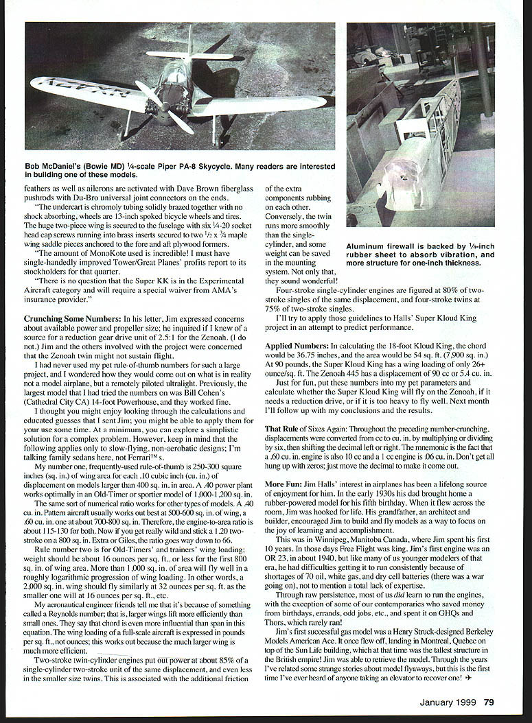
Drawings, cowl, and canopy are available for a 1/4-scale (60-inch) Skycycle from Vintage R/C Plans, 5105 Pine Hill Circle, Howell, MI 48843. Many have been successfully built and flown.
Perhaps all hope is not lost for a 1/3-scale kit; the old rule of thumb is that for every letter sent to a columnist, 10 are never written. Following that line of logic, some manufacturer could find a rather large market should it choose to produce a Skycycle kit.
Because of the prototype's complex fuselage shape (remember that a drop tank was adapted), huge canopy, and double compound-curved wing fillets, a fiberglass fuselage would be ideal. On the other hand, construction of the wings and empennage is conventional and could be done in built-up or foam form.
Although the Skycycle is a rare subject for scale modeling, a considerable amount of documentation is available. It is rare, but hardly obscure.
Hey manufacturers! There are a whole bunch of modelers who would stand in line to buy a 1/3-scale kit! Why spend time developing another P-51 when this opportunity is there?
These are strange times: automobiles grow smaller while model airplanes grow larger!
A Really Big KK:
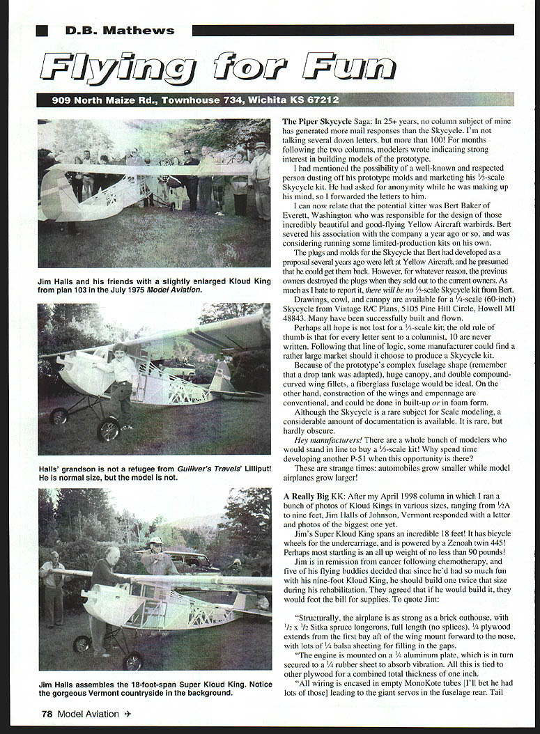
After my April 1998 column in which I ran a bunch of photos of Kloud Kings in various sizes, ranging from 1/2A to nine feet, Jim Halls of Johnson, Vermont responded with a letter and photos of the biggest one yet.
Jim's Super Kloud King spans an incredible 18 feet! It has bicycle wheels for the undercarriage and is powered by a Zenoah twin 445. Perhaps most startling is an all-up weight of no less than 90 pounds!
Jim is in remission from cancer following chemotherapy, and five of his flying buddies decided that since he'd had so much fun with his nine-foot Kloud King, he should build one twice that size during his rehabilitation. They agreed that if he would build it, they would foot the bill for supplies. To quote Jim:
- Structurally, the airplane is "as strong as a brick outhouse," with 1/2 x 1/2 Sitka spruce longerons, full length (no splices). 1/4 plywood extends from the first bay aft of the wing mount forward to the nose, with lots of 1/4 balsa sheeting for filling in the gaps.
- The engine is mounted on a 1/8-inch aluminum plate, which is in turn secured to a 1/4-inch rubber sheet to absorb vibration. All this is tied to other plywood for a combined total thickness of one inch.
- All wiring is encased in empty MonoKote tubes (I'll bet he had lots of those) leading to the giant servos in the fuselage rear.
- Tail and ailerons are activated by Dave Brown fiberglass pushrods and Du-Bro universal joint connectors at the ends.
- The undercarriage is chromoly tubing, solidly brazed together — no shock-absorbing wheels; 13-inch spoked bicycle wheels with huge tires.
- The two-piece wing is secured to the fuselage with six 3/8-16 socket-head cap screws running into brass inserts secured to two 1/2 x 3/4-inch wing saddle pieces anchored fore and aft to plywood formers.
- The amount of MonoKote used is incredible — it must have single-handedly improved Tower/Great Planes profits for the quarter, no question. The Super KK Experimental Aircraft category will require a special waiver from the AMA's insurance provider.
Crunching Some Numbers:
In his letter Jim expressed concerns about available power, propeller size, and inquired if I knew a source of reduction-gear drive unit for Zenoah. Jim and others involved in the project were concerned the Zenoah twin might not sustain flight. I never used the "rule-of-thumb" numbers for such a large project, and wondered what the numbers would come out to in reality for a model airplane remotely piloted at this size.
Previously, the largest model I tried the numbers on was Bill Cohen's (Cathedral City, CA) 14-foot Powerhouse. It worked fine, and I thought you might enjoy looking through the calculations and educated guesses that I sent Jim; you might be able to apply them for your use some time. At a minimum, you can explore a simplistic solution for a complex problem. However, keep in mind that the following applies only to slow-flying, non-aerobatic designs; I'm talking family sedans here, not Ferraris!
- My number-one, frequently-used rule-of-thumb is 250–300 square inches (sq. in.) of wing area for each .10 cubic inch (cu. in.) of displacement on models larger than 400 sq. in. in area. A .40 power plant works optimally in an Old-Timer or sportier model of 1,000–1,200 sq. in.
- The same sort of numerical ratios works for other types of models. A .40 cu. in. pattern aircraft usually works out best at 500–600 sq. in. of wing, a .60 cu. in. at about 700–800 sq. in. Therefore, the engine-to-area ratio is about 115–130 for both. Now if you get really wild and stick a .120 two-stroke on an 800 sq. in. Extra or Giles, the ratio goes way down to 66.
- Rule number two is for Old-Timers and trainers' wing loading: weight should be about 16 ounces per sq. ft., or less for the first 800 sq. in. of wing area. More than 1,000 sq. in. of area will fly well in a roughly logarithmic progression of wing loading. In other words, at 2,000 sq. in. a wing should fly similarly at 32 ounces per sq. ft. as the smaller one will at 16 ounces per sq. ft.
My aeronautical engineering friends tell me that it's because of something called Reynolds number; that is, larger wings lift more efficiently than small ones. They say that chord is even more influential than span in this situation. The wing loading of a full-scale aircraft is expressed in pounds per sq. ft., not ounces; this works out because the much larger wing is much more efficient.
Two-stroke twin-cylinder engines put out power at about 85% of a single-cylinder two-stroke unit of the same displacement, and even less in the smaller-size twins. This is associated with the additional friction of the extra components rubbing on each other. Conversely, the twin runs more smoothly than the single-cylinder, and some weight can be saved in the mounting system. Not only that, they sound wonderful!
Four-stroke single-cylinder engines are figured at 80% of two-stroke singles of the same displacement, and four-stroke twins at 75% of two-stroke singles.
I'll try to apply those guidelines to Halls' Super Kloud King project in an attempt to predict performance.
Applied Numbers: In calculating the 18-foot Kloud King, the chord would be 36.75 inches, and the area would be 54 sq. ft. (7,900 sq. in.). At 90 pounds, the Super Kloud King has a wing loading of only 26.7 oz. per sq. ft. If the Zenoah 445 has a displacement of 90 cc (about 5.4 cu. in.), just for fun, put these numbers into my parameters and calculate whether the Super Kloud King will fly on the Zenoah, if it needs a reduction drive, or if it is too heavy to fly well. Next month I'll follow up with my conclusions and the results.
That Rule of Sixes Again:
Throughout the preceding number-crunching, displacements were converted from cc to cu. in. by multiplying or dividing by six, then shifting the decimal left or right. The mnemonic is the fact that a 10 cc engine is about .60 cu. in., and a 1 cc engine is .06 cu. in. Don't get all hung up with zeros; just move the decimal to make it come out.
More Fun:
Jim Halls' interest in airplanes has been a lifelong source of enjoyment for him. In the early 1930s his dad brought home a rubber-powered model for his fifth birthday. When it flew across the room, Jim was hooked for life. His grandfather, an architect and builder, encouraged Jim to build and fly models as a way to focus on the joys of learning and accomplishment.
This was in Winnipeg, Manitoba, Canada, where Jim spent his first 10 years. In those days Free Flight was king. Jim's first engine was an O&R .23 in about 1939. In those days modelers were short of materials because of shortages of oil, white gas, and dry cell batteries (there was a war going on), not to mention a total lack of textbooks.
Through raw persistence, most of us did learn to run the engines, with the exception of some of our contemporaries who saved money from birthdays, errands, and odd jobs and spent it on QHGs and Thor engines, which rarely ran!
Jim's first successful gas model was a Henry Struck–designed Berkeley Models American Ace. It once flew off, landing in Montreal, Quebec on top of the Sun Life building, which was the tallest structure in the British Empire. Jim was able to retrieve the model. Through the years I've related some strange stories about model flyaways, but this is the first time I've ever heard of anyone taking an elevator to recover one!
Transcribed from original scans by AI. Minor OCR errors may remain.

