
D.B. Mathews
Flying for Fun
909 North Maize Rd., Townhouse 734, Wichita KS 67212
Let's discuss a part of construction that is a common source of trouble for newcomers, and sometimes for more-experienced builders.
Hinging the movable surfaces of radio-control (RC) models is not too difficult anymore, but many models are seen with huge spaces between the halves (gaps), surfaces that bind when moved, surfaces that are not level, and worst of all, surfaces that are inadequately adhered to the model.
These hinging problems are not limited to homebuilt models but are frequently found on economy (ARF — Almost-Ready-to-Fly; RTF — Ready-to-Fly; RTC — Ready-to-Cover; ARTC — Almost-Ready-to-Cover, etc.) factory-built models. Occasionally hinge installations are so poor that it's necessary to cut off the hinges and redo them.
In the early days of escapement RC, so little power was available that the rule of thumb was: with the pushrod off, the surface should fall up or down from its own weight. This free movement was also considered necessary for control-line (CL) models.
Common practice was to use a section of thin music wire embedded by its ends in one surface, running inside a section of aluminum tube that was adhered to the other surface. Alternately, sections of cloth were adhered to the surfaces in an over-and-under pattern — a method still used often on CL models.
With the considerable increase in force of modern servos, there is no longer a need for hinges that are that free-moving, but it still represents a worthwhile goal.
The following might be "old hat" to experienced modelers, but they might pick up a tidbit. I've hinged a model or two in my time; this is where I am at the moment, and I fully expect to learn more soon.
The most common problem in new fliers' airplanes is hinging the control surfaces; many RTF models even have improperly factory-installed hinges.
Hinges should be adhered strongly enough to resist pulling when the surface is given a good tug with one's fingers. Surfaces should move freely without binding when run to the limits of the specified deflection.
Conversely, the space between the mating halves of the surfaces should be at a minimum for improved efficiency. Small gaps reduce the amount of needed deflection by reducing airflow through the opening, resulting in smoother flights, less stress on servos and linkages, and prevention of flutter at higher speeds.
If an ARF model's hinges are loose, flow medium CyA (cyanoacrylate glue) into the slots. If the gap is excessive, or the surfaces bind when flexed, it may be necessary to cut the hinges off flush at both surfaces with a sharp modeling knife and rehinge using one of the products described below.
Any rubbing or binding in the linkage between the servo and the moving surfaces must be corrected. Do not fly a model airplane with loose or binding hinges!
Several classes of hinges are available, and selection depends on application; small models with thin surfaces may require ultraminiature hinges.
Figure-Eight Hinges
Ultraminiature models may require easy-to-make figure-8 hinges made from kite cord.
- Drill or punch small holes opposite each other in the wood.
- Coat the tip of a 24-inch length of cord with thin CyA and shape the tip to a point.
- Lace the cord back and forth over and under, much like shoelaces, into a snug figure-8 pattern between the surfaces.
- Feed the last turn back through the adjacent hole for a snug fit, clip off the cord, and coat the area around the holes with thin CyA.
The hinge must be snug or the control surface will flap. Figure-8 hinges were used on models in the early days when nothing else was available; now they are seen mainly on tiny RC models.
Laminated Hinges
Perhaps the simplest type of hinge to install is made by laminating three layers of tough plastic. Identified in the modeling literature under various names (ranging from "hot hinges" to brand names), laminated hinges are available from several manufacturers and are included in some kits' hardware packages. They consist of an absorbent outer layer on each side to wick thin CyA into the surrounding wood, with a flexible, strong inner core.
Mylar™ layered hinges: small .02–.06 models with surfaces as thin as 1/32 inch can be hinged with layered hinges cut into smaller sections. At the other extreme, these hinges can be used on large models by applying double width or multiple spots along hinge lines. Laminated hinges are designed to be adhered with thin CyA.
To install laminated hinges:
- Pencil-draw the centerline on both surfaces to be hinged. Mark hinge locations referring to the kit plans.
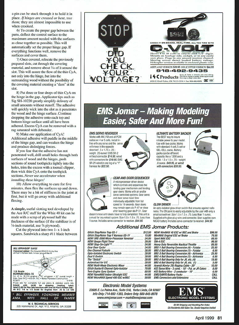
- Using a modeling knife with a fresh #11 blade, carefully cut a shallow slit at each hinge location. The first slits should be shallow to serve as guides for deeper cuts. The slit should be slightly wider than the actual hinge.
- Make three or four additional cuts in the same line, going deeper each time. Concentrate on staying in the slit and keeping the blade aimed into the center of the wood to avoid penetrating the top or bottom surfaces. Use a wiggling motion with the knife handle and continue until the slot is about 1/2 inch deep.
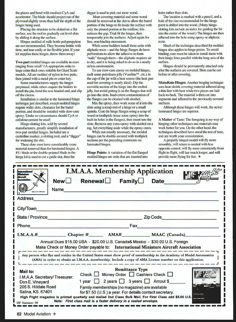
- After the required slots have been cut, slice the square corners off the hinges with scissors and push a test hinge into each slot to check fit. If necessary, reinsert the blade and move it back and forth a few times, then recheck until the hinge will slide into the slot. Avoid creating too much space; it may not allow good adhesion.
- Carefully test-fit the surfaces by sliding all hinges into the slots on one surface, then wiggling the other surface at an angle over the hinges starting at one end and working to the other. If a hinge slides too far into a slot when fitting, push it back into position with the point of a knife or a small pin.
- To set the proper hinge gap, deflect the control surface to the maximum amount needed with the surfaces as close together as possible. This automatically sets the proper hinge gap. If everything functions well, remove the surfaces and cover them.
- Once covered, relocate the prepared slots, cut through the covering material, and remove about 1/16 inch of covering around each slot. This ensures thin CyA can flow into the hinge and surrounding wood without the covering creating a dam.
- Put three or four drops of thin CyA on the hinge in the gap. Applicator tips (such as Sig SH-10220) simplify delivery of small amounts without runoff. The adhesive will quickly wick into the slot as it penetrates the wood and hinge surface. Continue until all hinge locations are adhered. Remove excess CyA with a rag and debonder.
- Make only one application of CyA at each hinge. Additional adhesive will puddle in the middle of the hinge gap, can weaken the hinge, and may produce dislodging forces. If you fear that the adhesive has not penetrated well, drill small holes through both surfaces and the hinge, push toothpick sections tightly into the holes, trim the excess, and wick thin CyA onto the toothpick sections. Never use accelerator when installing these hinges!
- Allow everything to cure for five minutes, then flex the surfaces up and down. There may be a bit of stiffness initially, but it will ease with additional flexing.
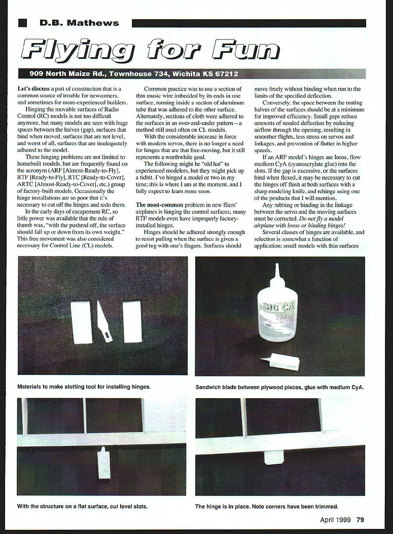
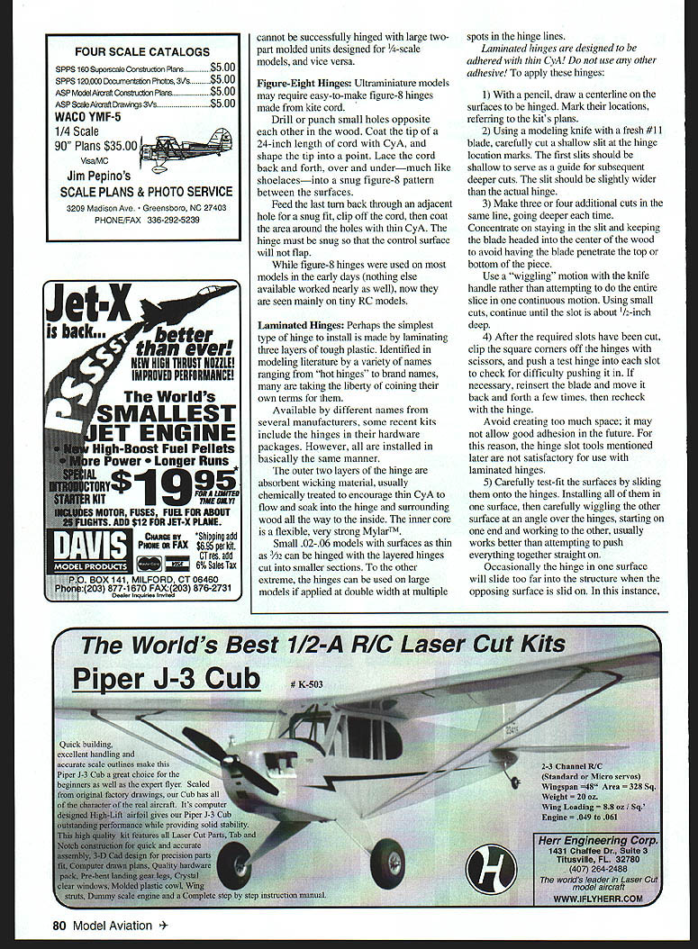
A simple slotting tool developed by the Ace R/C staff for the Whiz 40 kit can be made with a scrap of plywood half the thickness of the surface (for a 1/4-inch stabilizer, use 1/8-inch plywood). Cut two 1 x 1-inch squares, sandwich a sharp #11 blade between them, glue the assembly with medium CyA, and clamp it on a flat surface. The tool will cut level slots for laminated hinges (corners must be trimmed). It is not suitable for large two-part molded units and vice versa.
Two-Part Molded Hinges
Two-part molded hinges are available in sizes ranging from small 1/2A units to large extra-thick ones suitable for giant-scale models. All are molded of nylon in two parts, then joined with a metal pin or cotter key. Some manufacturers supply the hinges pre-pinned; others require the builder to install the pin, bend the nonheaded end, and clip off the excess.
Installation is similar to laminated-hinge technique, but molded hinges require wider slots and clearance for the barrel portion. They should be installed with slow-cure epoxy. Under no circumstance should CyA or cellulose cement be used.
Hinge-slotting kits, sold by several manufacturers, greatly simplify installation of two-part molded hinges. Kits typically include a centering marker, a slotting tool, and a digger for widening the slot.
- Cut a guide slot with a #11 blade or the double-pointed blade in the hinge kit.
- Use the digger to remove more wood.
- Remove additional covering material and some wood at the slot so the barrel portion of the hinge fits inside the surface with only the pin portion in the midline; this reduces the gap.
- Trial-fit the hinges and temporarily join the surfaces. Adjust until movement is free and nonbinding.
While some builders use aliphatic resins (wood glue) — and hinge flanges have perforations to allow the adhesive to form "nails" through them — aliphatic glue requires air to dry and must do so in a nearly airless environment inside the slot, which can be problematic.
To use slow-cure epoxy on molded hinges:
- Melt some petroleum jelly (Vaseline, etc.) in the cap of the jar with a heat source (the heat gun used for covering works well).
- Dip the movable section of the hinge into the melted jelly, avoiding the flanges that will go into the slots. Clean any inadvertent contamination of the flanges with alcohol.
- Mix the epoxy, then work some of it into the slots using a scrap hinge or a small spatula. Coat the hinge flanges (tease epoxy into the built-in holes in the flanges), then insert into the slots.
- Remove extra epoxy with alcohol on a rag and set aside while the epoxy cures.
As an extra precaution, molded hinges can be double-secured with toothpick sections as described for laminated hinges.
Hinges molded of milk-bottle polypropylene are not recommended: they become brittle with time and tear easily at the flexible joint. If your kit supplies these hinges, discard them.
Hinge Points
A variation of flat-flanged molded hinges are hinge points that are inserted into holes rather than slots.
- Mark the location with a pencil and drill a hole of the size recommended for the hinge point (many hinge kits include an index for guiding the bit into the center of the wood).
- Adhere the hinge into the hole using epoxy or aliphatic resin.
Much of the technique described for molded hinges also applies to hinge points. To avoid binding, install them with their hinge lines parallel to the long axis of the surface. Hinges should be permanently attached only after the surfaces are covered. Slots can be cut before or after covering.
MonoKote Hinges
Another hinging technique uses heat-shrink covering material adhered along a thin line with heat while two pieces are laid back-to-back. The material is then cut into segments and adhered to the previously covered surfaces.
Although these hinges will work, the newer laminated hinges are superior.
A Matter of Taste
The foregoing is my way of hinging; other techniques and materials may work better for you. On the other hand, the techniques described have stood the test of time and are worth your consideration.
A properly hinged model will fly more smoothly, return to neutral with less opposite control, fly more consistently from flight to flight, last much longer, and provide more flying for fun.
Transcribed from original scans by AI. Minor OCR errors may remain.

