

D.B. Mathews
909 North Maize Rd., Townhouse 734, Wichita KS 67212
Flying for Fun
A recent conversation with a modeling friend of 40 years called my attention to confusion about several columns I've written on power loading, engine displacement relative to wing area and gross weight.
It may well be the result of oversimplification on my part. As I illustrated with several photos, some models are designed to handle incredible amounts of power, while others are unable to do so; the difference lies in the rigging. I'll try to clarify that this month.
Underpowering is not usually a problem, since the model will likely barely fly anyway; on the other hand, overpowering a model is fraught with potential aerodynamic problems.
The following will be fundamental to some readers, but hopefully helpful to others. For the purpose of simplicity, I will confine my comments to forces that affect the pitch attitude of the model, leaving roll and yaw for another time.
(I have no delusions of expertise on matters aerodynamic; what little I know has been learned from cut-and-try.)
Why Some Models Climb As Power Is Added
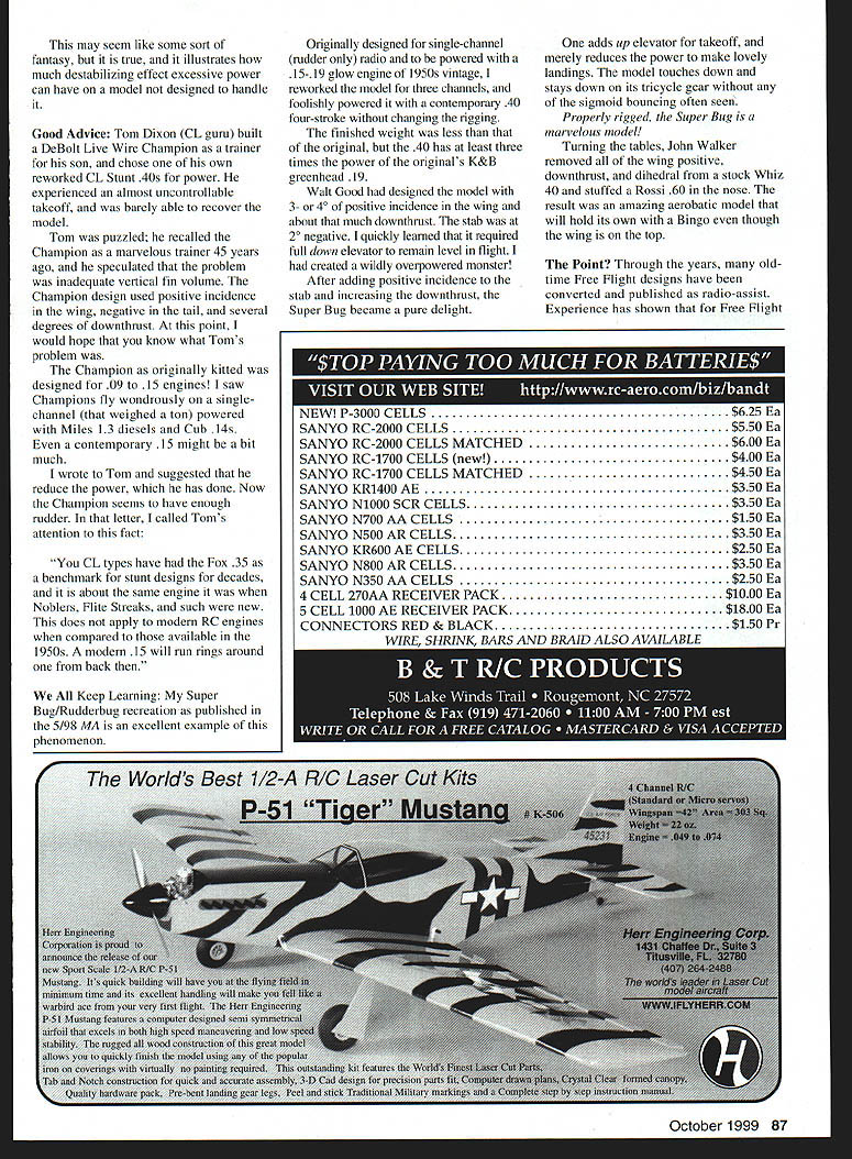
My crude Illustration 1 attempts to illustrate the reference to the engine, horizontal stabilizer, and wing to the datum line of the model.
By definition, the datum line is a reference, fore and aft, on the fuselage to which everything is related during design, assembly, and rigging. Datum line and the angle at which the model flies through the air (angle of attack) in flight are not necessarily the same.
Fully aerobatic Radio Control (RC) and Control Line (CL) models are usually set up "zero, zero, zero"; they have no downthrust in the power plant, or incidence in the wing or stabilizer in reference to the datum line.
Set up this way, the fully-aerobatic model has no inherent stability; if its nose is pushed down, it stays down; if it is turned, it will continue to turn until told to stop. Inverted, upright, or knife-edge, the aerobatic model is trimmed to fly where it's put. It is essentially unstable, and the only limit of power is weight and structural integrity.
On the other end of this spectrum, RC trainers, power and Rubber Free Flight, and many sport RC designs have angular variations from the datum line for stability reasons. The models are rigged to return to level flight on their own, which is ideal for their designed purpose.
However, because of these angular differences, the models can be uncontrollable when excessive power is used.
In Illustration 1, the trainer has several degrees of engine downthrust and positive incidence in the wing; that is, the leading edge is higher than the trailing edge when a separate datum line is drawn from the center of the airfoil's leading and trailing edges. The horizontal stabilizer is set with negative incidence (leading edge down).
This combination of angular differences is called decalage.
In Illustration 2, the model is in flight. The wing datum line is parallel with the flight path (angle of attack), but the fuselage is pointed down. This nose-down attitude adds downthrust and negative incidence to the tail (the equivalent of up elevator).
As the model passes more rapidly through the air when power is increased, the model will tend to climb. In another situation, where the power remains constant but the model is pushed into a dive with down-elevator, it will naturally return to level flight when the elevator is returned to neutral.
This is the way pitch-axis stability is built in — exactly what the designer wants in a trainer. This is also the reason instructors are heard to say, "throttle back and let go of the sticks" when a student pilot's model gets out of control.
All of these desirable qualities become a liability if the model is grossly overpowered; its velocity exceeds the built-in stability by overemphasizing it. Look at Illustration 2, and consider what would occur if the model flew really fast with that decalage.
Though engine downthrust is used to help control this climb tendency, there are limits to how much can be used. In excess, downthrust will require up elevator when the engine is running wide open; yet, when throttled back, the model will tend to stall.
If a model flown under continuous power needs more than 5° of downthrust, you're wasting so much power that you might as well use a smaller power plant.
In Free Flight, where power is applied for a short time, and in the case of rubber power delivered in short bursts of declining thrust, much more downthrust can (and sometimes should) be used.
Free Flight designs also incorporate considerable angular differences between the wing and stabilizer to prevent any tendency for the model to drop its nose and dive in under power. Conversely, if a Free Flight model passes the vertical and becomes inverted, look at the drawing to see what will happen.
A Classic Example of Raw Power
In the 1950s, as multichannel reed radios became available, separate classes of RC competition were created to provide a chance for those with less-complex gear to still compete separately from the full four- (actually eight-) channel reed aircraft.
For a few years, there were classes based on the number of surfaces controlled. One was Class II, limited to two movable surfaces. You may find this hard to believe, but in some instances the choice was rudder and throttle! The throttle — not an elevator — was used to control pitch attitude.
These strange designs were set up to loop, and even roll. Vast amounts of power (such as .45s on what would be considered .19 models) were coupled to huge amounts of downthrust (such as 20°) and enough right thrust to control torque. Negative incidence was built into the stabilizer.
The models were often steerable on the ground, so takeoff involved applying full throttle until takeoff speed was reached, then the thrust was reduced to eliminate the force from the downthrust, allowing the model to take off.
In flight, the stab negative was overcome by adjusting the throttle; that is, climb and descent were a pure power function. To loop, full power was added to generate forward speed, then the throttle was chopped, forcing the model up and over from the effect of the stabilizer. To roll, power and rudder were added at the top of the loop, where the dihedral was ineffective in the roll axis since the wing was inverted.
This may seem like some sort of fantasy, but it is true, and it illustrates how much destabilizing effect excessive power can have on a model not designed to handle it.
Good Advice
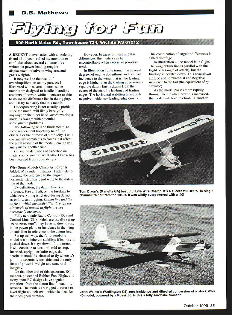
Tom Dixon (CL guru) built a DeBolt Live Wire Champion as a trainer for his son, and chose one of his own reworked CL Stunt .40s for power. He experienced an almost uncontrollable takeoff, and was barely able to recover the model.
Tom was puzzled; he recalled the Champion as a marvelous trainer 45 years ago, and he speculated that the problem was inadequate vertical fin volume. The Champion design used positive incidence in the wing, negative in the tail, and several degrees of downthrust. At this point, I would hope that you know what Tom's problem was.
The Champion as originally kitted was designed for .09 to .15 engines. I saw Champions fly wondrously on a single-channel (that weighed a ton) powered with Miles 1.3 diesels and Cub .14s. Even a contemporary .15 might be a bit much.
I wrote to Tom and suggested that he reduce the power, which he has done. Now the Champion seems to have enough rudder. In that letter, I called Tom's attention to this fact:
"You CL types have had the Fox .35 as a benchmark for stunt designs for decades, and it is about the same engine it was when Noblers, Elite Streaks, and such were new. This does not apply to modern RC engines when compared to those available in the 1950s. A modern .15 will run rings around one from back then."
We All Keep Learning
My Super Bug/Rudderbug recreation as published in the 5/98 MA is an excellent example of this phenomenon.
Originally designed for single-channel (rudder only) radio and to be powered with a .15-.19 glow engine of 1950s vintage, I reworked the model for three channels, and foolishly powered it with a contemporary .40 four-stroke without changing the rigging.
The finished weight was less than that of the original, but the .40 has at least three times the power of the original's K&B Greenhead .19.
Walt Good had designed the model with 3 or 4° of positive incidence in the wing and about that much downthrust. The stab was at 2° negative. I quickly learned that it required full down elevator to remain level in flight. I had created a wildly overpowered monster!
After adding positive incidence to the stab and increasing the downthrust, the Super Bug became a pure delight.
One adds up elevator for takeoff, and merely reduces the power to make lovely landings. The model touches down and stays down on its tricycle gear without any of the stupid bouncing often seen.
Properly rigged, the Super Bug is a marvelous model!
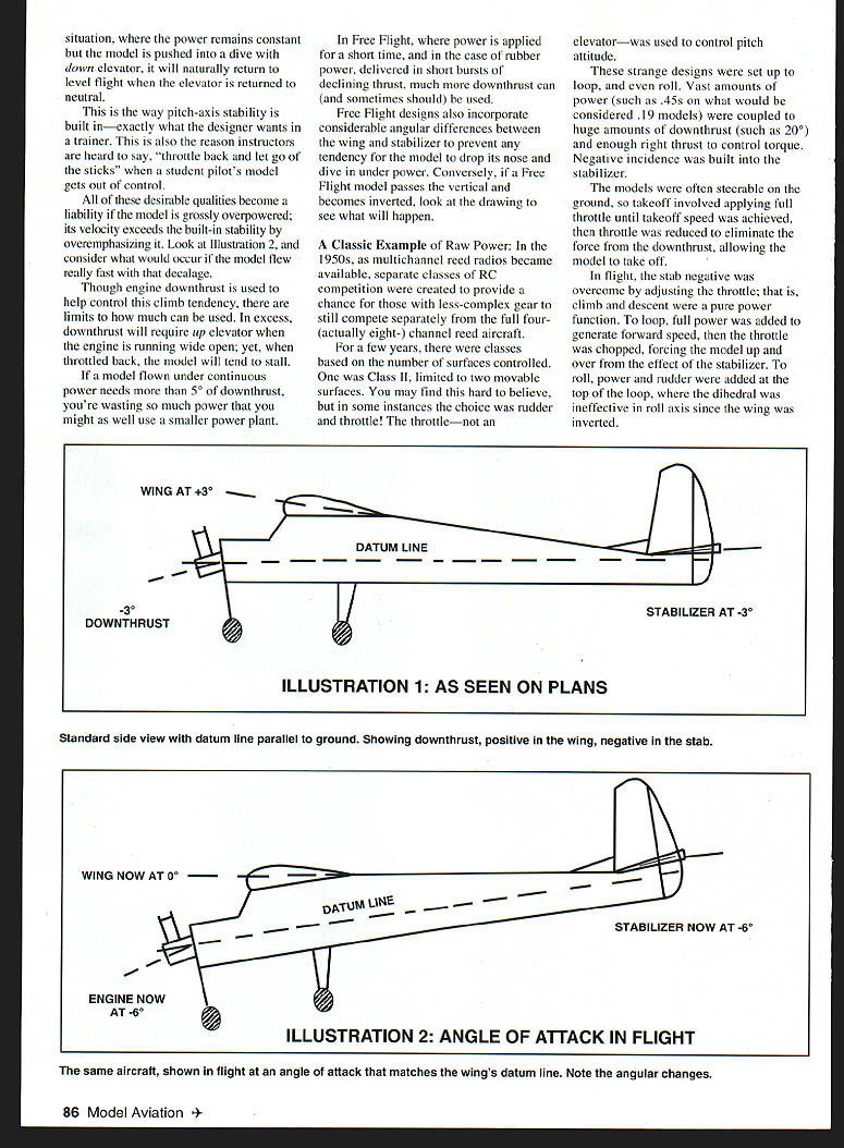
Turning the tables, John Walker removed all the wing positive incidence and downthrust from a stock Whiz .40 and stuffed a Rossi .60 in the nose. The result was an amazing aerobatic model that will hold its own with a Bingo even though the wing is on the top.
The Point
Through the years, many old-time Free Flight designs have been converted and published as radio-assist. Experience has shown that for Free Flight designs of the 1930s and 1940s, half of the original engine displacement is plenty. Power plants of the 1950s should be calculated at 70%–80% of modern engines.
If the designer of your plans or kit says to use a .40–.50 engine, stick with it or be prepared to make aerodynamic changes. It was once common for manufacturers to fudge a bit on engine size recommendations to broaden a kit's sales appeal. Even then, sticking in the middle of the range was a pretty sure bet.
Perhaps all of this will clarify things for those who have written to me through the years relating wild takeoff handling with old-timers and early-era RC trainers, and for those who have written asking why I don't use downthrust sometimes.
To Summarize
The amount of power used in a model has a direct impact on its design. Modern aerobatic designs are high-powered and have no angular differences relative to their datum lines. They are inherently unstable.
Older model designs and contemporary trainers have angular variations from the datum line built into them. At moderate flying velocities, these variations create inherent stability. Unfortunately, at higher speeds these incidence angles add permanent up elevator. Overpowered, they will tend to take off and hit you in the back of the head!
Transcribed from original scans by AI. Minor OCR errors may remain.

