
Flying For Fun: Stress Management
Stress Management
Have you noticed that the latest hot topic for seminars around the country is stress management? Not hard to understand why, is it? It occurs to me that people with a hobby like ours are better able to blow off stresses from the real world than those whose recreational activities are nonparticipatory. I'm talking couch potatoes here.
As a matter of fact, one of the stress-management techniques most often recommended in those seminars is to get a hobby. That is certainly an excellent solution — as long as the hobby doesn't become stressful.
I hear of flying groups whose members somehow let themselves get too serious about building and flying, but most of us make a concentrated effort to relax and have a good time.
Frankly, it's unfair to the flier who desperately needs the stress relief to be around someone who is wound up tighter than a Wakefield. After all, aren't we flying for fun? If someone is obviously stressed, remind them that this is for fun!
That Missing Drawing
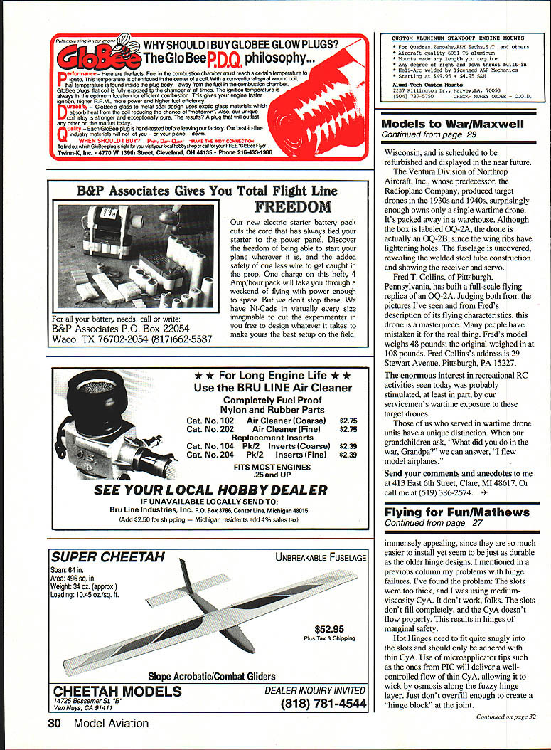
My April 1992 column described Brian Ulwin's airfoil modifications to his Goldberg Eagle II. The promised drawing of the new airfoil somehow ended up as part of William McComb's article on vertical tail size. The drawing is reprinted in this issue. Raising the entry at the leading edge changed the characteristics of the model. I was attempting to show another justification for the semisymmetrical airfoil set at a markedly positive angle of attack that I used on the Whiz 40 project.
Wish I'd Thought of It
Although the 42-page "Kit-Builder's Guide" that is included in the above-mentioned Ace R/C Whiz 40 kit (and is also available separately) carries my byline, some of the hints and all of the artwork and photos were done at the factory. This makes for a neat arrangement. If the reader disagrees with suggested techniques, I can blame Tom Runge and his staff; if, on the other hand, the reader sees something he thinks is brilliant, I can take the credit.
One of the really useful suggestions that I can't take any credit for at all is designed to prevent the usual dust-on-everything problem associated with sanding a model in the shop. Purchase a box fan at a discounter, along with a furnace filter that will cover the back of the fan. Tape the filter onto the back, and run the fan while sanding. The fan will draw the sawdust into the filter and prevent it from spreading all over the room. Now, that one I wish I'd thought of.
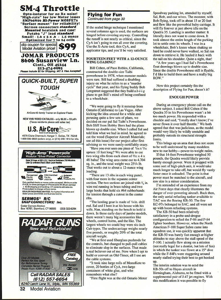
Included in the kit is another gadget I wish I'd invented. The photo and drawing pretty well illustrate the use of an X-Acto blade glued (using CyA, cyanoacrylate glue) between two scraps of appropriate wood thickness to center it with the thickness of the surface to be slotted. This works amazingly well as a slotting guide for Hot Hinges. If you've tried freehanding these or used a hinge-slotting tool and found the slots to be much too large, you can appreciate the practicality of this simple little device.
A word of caution concerning Hot Hinges and the other fuzzy-surfaced one-piece flexible hinges: these hinges are immensely appealing, since they are so much easier to install yet seem to be just as durable as the older hinge designs. I mentioned in the previous column my problems with hinge failures. I've found the problem: the slots were too thick, and I was using medium-viscosity CyA. It doesn't work, folks. The slots don't fill completely, and the CyA doesn't flow properly. This results in hinges of marginal safety.
Hot Hinges need to fit quite snugly into the slots and should only be adhered with thin CyA. Use of microcapillary tips such as the ones from PIC will deliver a well-controlled flow of thin CyA, allowing it to wick by osmosis along the fuzzy hinge layer. Just don't overfill enough to create a "hinge block" at the joint.
If the sealed-hinge technique I mentioned several columns ago is used, the surfaces are hinged before covering anyway. Controlling the runoff is not nearly as critical, since the CyA isn't going to run all over the covering. Use the X-Acto tool, thin CyA, and applicator tips, and you'll be very satisfied.
Fourteen Feet with a 12-Ounce Wing Loading?
Bill Cohen, of Paso Robles, California, constructed the double-size Taibi Powerhouse in 1978, when monster models were rare. Bill had suffered a disabling injury on what he refers to as a "murder cycle" that year, and his flying buddy Bob Longstreet suggested that they build a biplane to get Bill's mind off being confined to a wheelchair.
"We were going to fly it nonstop from Ontario (California) to Las Vegas. After kicking the idea around for a while and perusing quite a few sets of plans, we decided on our pal Sal Taibi's Powerhouse. Bob Sliff from Hobby Horn had the plans blown up double size. When I called Sal and told him what we had in mind, he agreed to cut the wood (Superior Aircraft Materials; see ad this issue) for our project after first advising us we were surely certifiably crazy.
"Have you ever seen one piece of 7/16 x 7/16 spruce 10 feet long? We were able to cut two wing ribs from each sheet of 5/32 x 4 x 48 balsa! The wing area came out to 4,704 sq. in., and the total weight was 25-1/4 lb. That works out to about a 12-ounce wing loading.
"There are 13 ribs in each wing panel, with four more in the separate center section. The two sections are joined with 1/4-in. wire rod running in brass tubing and two large hooks that hold six #64 rubber bands for tension through a cutout in the center ribs.
"The landing gear is made of 1/4-in. drill rod. Sal and I bent it at his house with his wife, Nan, standing on the bench to hold it down. In those early days of jumbo models, there weren't many big accessories like wheels, control horns, and the like. The largest wheels we could buy were six-inch Cub types. The undercarriage weighs nearly five pounds, or roughly 20% of the total aircraft weight.
"We at first used fiberglass pushrods for the controls, but changed to pull-pull cables to eliminate slop in the surfaces. That made a real believer out of me. Now when I opt to build or convert an Old-Timer, all I use are the cable systems.
"It took nine large rolls of MonoKote to cover, 20 bottles of CyA, two large containers of white glue, and who remembers what else?
"First flight was at the old Ontario Motor Speedway parking lot, attended by myself, Sal, Bob, and our wives. The monster, with Bob flying, took off in about 15 or 20 feet and flew like the proverbial baby carriage. It will fly forever at just above idle on the Quadra 35. Landing is another matter. It literally does not want to come down. It took almost the entire length of the parking lot to settle onto its wheels. I was in a wheelchair; Bob's knees were shaking so hard he could never have walked, so Sal ran down to retrieve it. He hauled it back with the tail on his shoulder. Quite a sight, that!
"A few years ago I had Sal's Powerhouse float drawings blown up to double size. Since the double Powerhouse still is flyable, I'd like to build them and have a really big row."
Now this project certainly fits the description of flying for fun, doesn't it?
Enough Power
During an emergency phone call on the above subject, I asked Bill Cohen if the Quadra 35 in his Powerhouse wasn't a bit too much power. He responded with a chuckle and said, "I really don't know; I've flown it over half throttle." We both agreed that that was judicious, as the model would very likely be wildly unstable and probably outside its structural strength limits.
This brings up an area that does not seem to be well understood by many modelers—weight-to-power ratios. If that 14-foot Powerhouse weighed 50 pounds, the Quadra would likely provide the necessary power. Were it propped with some sort of high-pitch unit, it would take much longer to take off, but would fly vastly faster once it reached altitude. The power must be matched to the aircraft; overall size is a minor consideration.
I'm reminded of an experience from my Air Force days that clearly illustrates the danger of over-powering aircraft. Back then, the only aerial-refueling tanker available to TAC was the Boeing KB-50. The few KC-97s belonged to SAC, and all were set up with boom-refueling systems.
The KB-50 had been relatively satisfactory in a probe-and-drogue configuration to refuel the F-86 and F-84 fighter-bombers. However, when the North American F-100 Super Sabre came into squadron use, it was quickly apparent that the KB-50 was barely fast enough at higher altitudes to stay above the stall speed of the F-100. It actually flew along on a mission (not really legal for a unit) in which the tanker was flown at a 15° dive while the F-84Fs were staggered around nearly stalled trying their best to get hooked up.
The interim solution was to send the KB-50s off to have their J47s fitted with a supplemental pair of J47 jet engines. With this modification it was possible to fly above the fighters' stall speed, but other severe problems were encountered that nearly invalidated the KB-50J project.
One of the most startling observations I've ever made was during a refueling flight off the Texas coast early one morning in a KB-50J with the jets on and a pair of F-100s refueling. I happened to glance at the pilot's hands and discovered he was flying the airplane with the trim tabs—no use of the control column at all.
When I recovered my composure enough to ask why, I was advised that—although they didn't really want it known—otherwise the darned airplane would porpoise so badly that it could not be held level and was nearly uncontrollable with the J-47s running!
Additionally, although Hayes Air had reinforced some critical areas of the Boeing aircraft to handle the additional speed-imposed loads, they were extremely maintenance prone—actually verging on the unsafe. The safety record was, frankly, very poor, with numerous accessory failures such as loss of pressurization from blown windows, fuel system failures, failure of electronic gear from vibration levels, loss of access panels in flight, high-speed flutter and stress cracks, and many vibration-associated failures.
A perfectly useful aircraft with a good safety record and admired flying characteristics had been overpowered and overstressed well outside Boeing's original design limits, and as a result was a turkey.
So what does this have to do with model airplanes? I think quite a bit, really. Over the last several years, many of us old hats have commented to each other about the ridiculous oversized power plants, missized props, excess weight, and fast flying we see on some of the newcomers' models. As is the way of old hands, we disdainfully dismiss those obviously foolhardy choices as ignorance and shrug our shoulders in a know-it-all way.
After reflecting on this problem for a while, I think I can offer an explanation for this total disregard of basic aerodynamics. To wit: there's a whole generation of modelers who have never built, trimmed, and flown free-flight models, and consequently don't have the foggiest idea why thrust settings, balance points, horizontal and vertical fin size, prop diameter and pitch, aircraft speed, prop speed, structural air loads, etc., have to be dealt with in model designs.
We've all seen it at our flying sites: fluttering surfaces, high-speed stalls, wings and tails coming off, wild structural vibration, pitch and yaw instability, props making terrible noises as they blade-stall, pussycat models becoming wild monsters, overweight models dropping like stones and cleaning out the undercarriage, and all sorts of other gruesome stuff.
I've personally seen a Goldberg Ultimate with a SuperTiger S-2500, a Midwest Aero Star with an O.S. .90 four-stroke, and an Ace 4-40 powered by an Enya .45CX. One of the builder/pilots actually complained vociferously about the lack of ground clearance for a suitable prop.
At least these are not man-carrying vehicles and the pilot's life is not in jeopardy, but I'm not too comfortable about the spectators or the model. No one in his right mind would put a 350-hp Lycoming on a Cessna 150 without major structural strengthening, careful recalculation of the numbers, and jet-fighter flying experience. However, otherwise-rational modelers seem to do the equivalent all the time.
If the kit or plans indicate a power range, the designer means it. He isn't a fool, you know; if a larger engine and prop were safe, he'd recommend them, since the more power options that are usable with a design, the better the kit will sell. I wonder sometimes whether unscrupulous dealers aren't recommending those large engines because they sell for more bucks? Whatever the cause or factors, it behooves all of us to use a little common sense when selecting engines and props for our models. My favorite saying applies here: "Learn from the mistakes of others; you'll never live long enough to make them all by yourself."
Driggs or Culver
When I first saw Craig Williams's model, I identified it as a Driggs Dart, only to be told it was a Culver Dart. Having been wrong once or twice before, I figured I was off on the identification. But some little voice in the back of my head kept asking, "Are you sure?"
Just on a hunch, I dug out my well-used copy of Underwood and Collinge's The Lightplane Since 1909. There, on page 158, the aircraft is identified as the 1935 Dart Monosport G with a 90-horsepower Lambert. It is identified as an Al Mooney design.
Knowing that Al moved to Wichita when Culver bought out the Dart Co. clarifies the confusion. Obviously, the same basic design was built by both manufacturers and is indeed both a Dart and a Culver.
The side-by-side photo clearly displays a family resemblance, but since both the Dart and Cadet are quarter-scale, it is also obvious that the latter was considerably smaller.
As plane buffs know, Culver closed, and Mooney went on to produce a line of private aircraft in Texas. What isn't so well known is that he developed the single-place Mooney Mite here in Wichita before moving.
While watching at the 1946 AMA Nationals in Wichita, a buddy and I started looking into hangars around the Boeing ramps where the control-line events were held. We pecked into a locked wooden temporary structure to see a tiny, all-metal, low-wing aircraft that looked a bit like a miniature Mustang. We had no idea what it was, but were struck by the underwing air scoop and what appeared to be an inverted Crosley automobile engine.
By now you've guessed it: we were spying on the first prototype of the Mooney Mite. Needless to say, the Crosley engine was replaced with a Continental 65 before many flights had been completed.
Another aside that you might find of interest: the plant where Culvers were built still exists and is now used for manufacture of another product you might have heard about—Coleman lanterns and such.
The 1939 Dart
Craig Williams of Kansas City scratch-built his Culver Dart from Golden Era plans (John Eaton). It is all-wood (no foam), but does have a fiberglass cowl and pants. Total weight is only 14 pounds; the plane is powered by an O.S. 120 four-stroke swinging a 16 x 8 prop. Covering is Solartex painted with Poly U and Red Devil urethanes.
Needless to say, this quarter-scale project is out-of-the-rut, and was very impressive with how realistically and gently it flew. A really nice companion project for Mark Van Sant's Culver Cadet, which I featured in an earlier column. Wouldn't it be neat to somehow get the Dart, Cadet, and Marvin Reece's Mite in the air together? Hmmm.
Transcribed from original scans by AI. Minor OCR errors may remain.

