
FlyWorm
A look back at an improbable attempt to come up with a "better mousetrap" in those heady days when aviation was young.
Col. John A. de Vries, USAF, ret.
Background
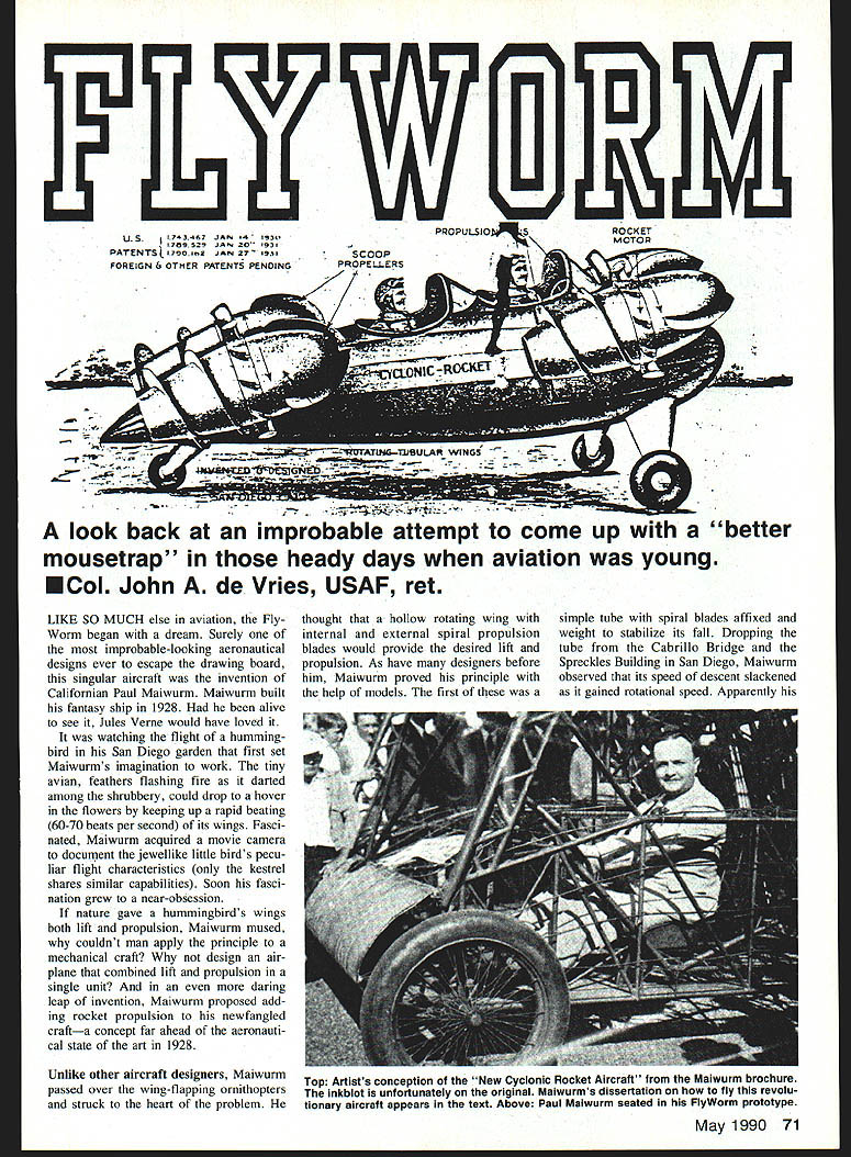
Like so much else in aviation, the FlyWorm began with a dream. Surely one of the most improbable-looking aeronautical designs ever to escape the drawing board, this singular aircraft was the invention of a Californian, Paul Maiwurm. Maiwurm built his fantasy ship in 1928. Had he been alive to see it, Jules Verne would have loved it.
It was watching the flight of a hummingbird in his San Diego garden that first set Maiwurm's imagination to work. The tiny avian, feathers flashing fire as it darted among the shrubbery, could drop or hover in the flowers by keeping up a rapid beating (60–70 beats per second) of its wings. Fascinated, Maiwurm acquired a movie camera to document the jewellike little bird's peculiar flight characteristics (only the kestrel shares similar capabilities). Soon his fascination grew to a near obsession.
If nature gave a hummingbird's wings both lift and propulsion, Maiwurm mused, why couldn't man apply the principle to a mechanical craft? Why not design an airplane that combined lift and propulsion in a single unit? And in an even more daring leap of invention, Maiwurm proposed adding rocket propulsion to his newfangled craft — a concept far ahead of the aeronautical state of the art in 1928.
Early experiments
Unlike other aircraft designers, Maiwurm passed over the wing-flapping ornithopters and struck to the heart of the problem. He thought that a hollow rotating wing with internal and external spiral propulsion blades would provide the desired lift and propulsion. As have many designers before him, Maiwurm proved his principle with the help of models.
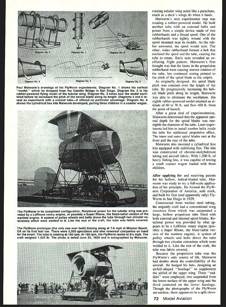
The first of these was a simple tube with spiral blades affixed and weight to stabilize its fall. Dropping the tube from the Cabrillo Bridge and the Spreckels Building in San Diego, Maiwurm observed that its speed of descent slackened as it gained rotational speed. Apparently this effect increased as the tube rotated faster, indicating a lifting influence from the spiraled surfaces.
The next experimental step was creating a rubber-powered model. He built another tube with an external helix for power. The simple device used two rubber bands on a thread spool; the rubber bands were tightly wound on the spool mounted near its middle. As the rubber unwound the spool would turn; the wider rubber band formed a belt which, enclosing the spool, caused the tube to rotate. Early tests revealed an oscillating flight pattern. Maiwurm's first thought was knots in the propulsion rubber band causing uneven rotation. Continued testing pointed to the pitch of the spiral blade as the culprit. As originally designed the spiral blade pitch was constant over the length of the tube. By progressively increasing the helical blade pitch along its length, Maiwurm was able to eliminate the oscillation. An eighth rubber-powered model attained an altitude of 60–70 ft and flew 400 ft from the point of launch.
After a great deal of experimentation, Maiwurm determined the apparent optimal depth of the spiral blades — one-eighth the diameter of the tube. Later experiments led him to install another helix inside the tube for additional propulsive effect; the inner and outer spiral blades met front to rear in the tube. Maiwurm also invented a cylindrical box kite equipped with stabilizing fins. The kite, constructed of chrome-molybdenum tubing and aircraft fabric, lifted 1,500 ft of heavy fishing line capable of towing a small coaster wagon loaded with three children.
Full-scale FlyWorm
After applying for and receiving patents on the hollow helical-bladed tube, Maiwurm was ready to try a full-scale application of the principle. He formed the FlyWorm Corporation of America, sold stock and built the first full-scale FlyWorm in San Diego in 1929.
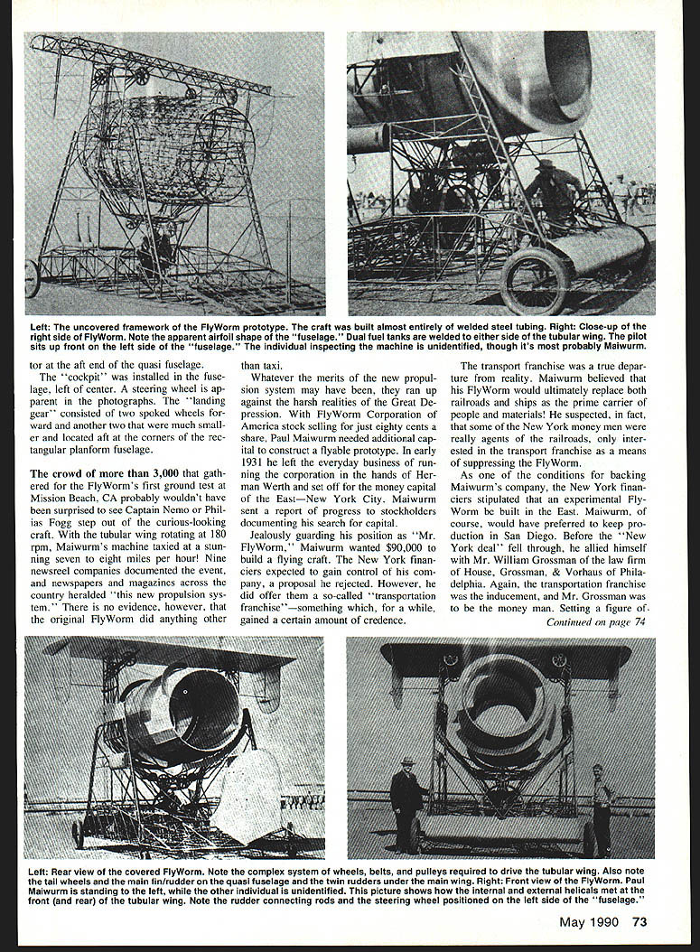
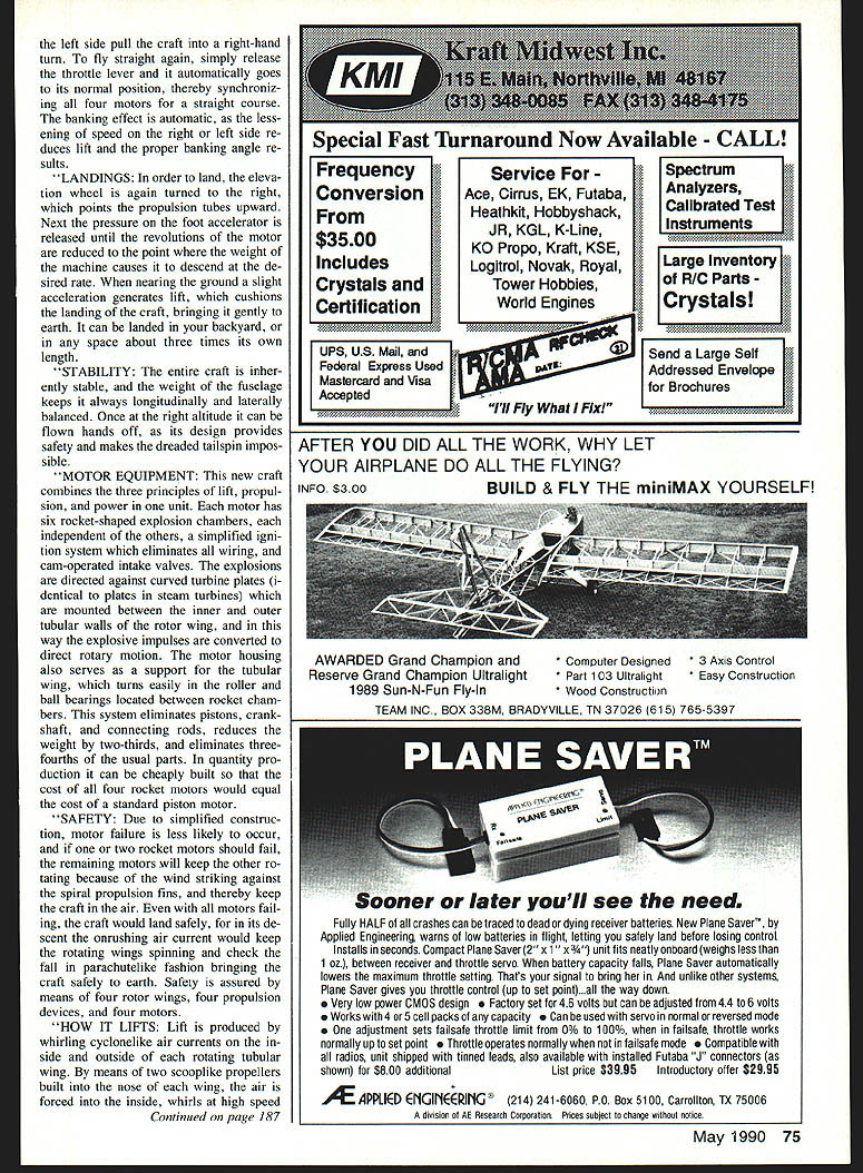
Constructed of welded steel tubing, the ungainly craft had a conventional wing structure suspended beneath a large hollow propulsion tube fitted with both external and internal spiral blades. Rotational power was provided by what appears to have been a LeRhone rotary engine, possibly a Super LeRhone wartime engine. A system of pulleys, wheels and belts drove the tube through two circular extensions welded to the tube. Like the rest of the craft the tube was fabric covered.
Because the propulsion tube was the FlyWorm's source of lift, Maiwurm, doubtful about the controllability of the aircraft, hedged his bets by designing an airfoil-shaped fuselage to supplement the airfoil of the upper wing. Three rudders were employed: two suspended from the lower surface of the upper wing and the third centered on the lower fuselage. Though the photographs of the FlyWorm are unclear, there appears to be a split elevator at the aft end of the quasi-fuselage.
The cockpit was installed in the fuselage, left of center. A steering wheel is apparent in the photographs. The landing gear consisted of two spoked wheels forward and two much smaller wheels located aft at the corners of the rectangular-planform fuselage.
Public demonstration
A crowd of more than 3,000 gathered for the FlyWorm's first ground test at Mission Beach, California. With the tubular wing rotating at 180 rpm, Maiwurm's machine taxied at a stunning seven to eight miles per hour. Nine newsreel companies documented the event, and newspapers and magazines across the country heralded "this new propulsion system." There is no evidence, however, that the original FlyWorm did anything other than taxi.
Financial troubles and the end of the project
Whatever the merits of the new propulsion system may have been, they ran up against the harsh realities of the Great Depression. With FlyWorm Corporation of America stock selling for just eighty cents a share, Paul Maiwurm needed additional capital to construct a flyable prototype. In early 1931 he left the everyday business of running the corporation in the hands of Herman Werth and set off for the money capital of the East — New York City. Maiwurm sent a report of research to stockholders documenting his search for capital.
Jealously guarding his position as "Mr. FlyWorm," Maiwurm wanted $90,000 to build a flying craft. The New York financiers expected to gain control of his company, a proposal he rejected. However, he did offer them a so-called "transportation franchise" — something which, for a while, gained a certain amount of credence.
The transport franchise was a true departure from reality. Maiwurm believed that his FlyWorm would ultimately replace both railroads and ships as the prime carrier of people and materials. He suspected, in fact, that some of the New York money men were really agents of the railroads, only interested in the transport franchise as a means of suppressing the FlyWorm.
As one of the conditions for backing Maiwurm's company, the New York financiers stipulated that an experimental FlyWorm be built in the East. Maiwurm, of course, would have preferred to keep production in San Diego. Before the "New York deal" fell through, he allied himself with William Grossman of the law firm of House, Grossman & Voorhis of Philadelphia. Again, the transportation franchise was the inducement, and Mr. Grossman was to be the money man. Setting a figure of $250,000 as their goal, they offered exclusive transportation-franchise rights for purchase. Before the two men had finalized negotiations, however, Mr. Grossman suddenly died while giving a talk to a fraternal order.
Though he knew of no one to take Grossman's place, as of 25 June 1931 Maiwurm was still optimistic about financing his dream. He turned to his stockholders in San Diego for additional funds, but they apparently didn't share his enthusiasm, and Maiwurm never found the capital to build another FlyWorm.
The New Cyclonic Rocket Aircraft
Before fading into the mists of history, Maiwurm had one last great inspiration: "The New Cyclonic Rocket Aircraft." This was to be a tandem two-place aircraft of common construction — steel tubing and fabric covering — but entirely without conventional control or lifting surfaces. The following is taken from Maiwurm's advertising brochure and describes his proposed craft and operating concept.
#### Description of the Cyclonic-Rocket Aircraft
The illustration on the front page showed exactly what the new "Fliver Plane" would look like when completed. It was twelve feet long, five feet four inches high, and a trifle wider than the average auto garage.
Anyone could learn to pilot this craft in less than an hour's time, as its operation was simpler than that of an auto, and no skill or pilot qualifications were necessary. This was accomplished through simplifying and unifying the control system. Here was the first aircraft that had neither conventional wing, propeller, nor motor. The usual ailerons, stabilizers, elevators, and rudder were completely eliminated.
Taking off
- The pilot starts the four rocket motors by giving the propulsion tube a quick whirl. This is easily done and is safer than cranking an automobile, as no backfiring can take place.
- Next he seats himself and turns the elevation wheel to the right — like a standard automobile steering mechanism — thereby placing all four rotating tubular wings on an angle from 30 to 45 degrees.
- He holds his left foot on the brake and his right on the accelerator, and by gradually pressing it down uniformly increases the revolutions of all four rocket-turbine motors, which are synchronized so their speed remains identical.
- The craft begins to lift and takes off from a standing start on an angular path until the desired altitude is reached.
Flying level
After reaching the desired altitude, the elevation wheel is turned to the left, which places all four propulsion tubes in a more horizontal position until the altimeter shows the craft is no longer climbing.
Banking and turning
Banking and turning are accomplished by two throttle levers located on either side of the cockpit. To make a right turn the right-hand lever is pulled back, throttling both motors on the right side; the higher-speed motors on the left develop the greater thrust, causing the craft to bank and turn. When the desired heading is obtained, the throttles are opened to full speed and the machine resumes level flight.
Landings
To land, the elevation wheel is again turned to the right, which points the propulsion tubes upward. Next the pressure on the foot accelerator is released until the revolutions of the motors are reduced to the point where the weight of the machine causes it to descend at the desired rate. When nearing the ground a slight acceleration generates lift, which cushions the landing of the craft, bringing it gently to earth. It could be landed in a backyard, or in any space above about three times its own length.
Stability
The brochure claimed the entire craft would be inherently stable, and that the weight of the fuselage would keep it always longitudinally and laterally balanced. Once at the right altitude it could be flown hands-off, as its design supposedly made the dreaded tailspin impossible.
Motor equipment
This new craft combined the three principles of lift, propulsion, and power in one unit. Each motor had six rocket-shaped explosion chambers, each independent of the others, a simplified ignition system which eliminated all wiring, and cam-operated intake valves. The explosions were directed against curved turbine plates (identical to plates in steam turbines) mounted between the inner and outer tubular walls of the rotor wing; the explosive impulses were converted to direct rotary motion. The motor housing also served as a support for the tubular wing, which turned easily in the roller and ball bearings located between rocket chambers. This system eliminated pistons, crankshaft, and connecting rods, reduced the weight by two-thirds, and eliminated three-fourths of the usual parts. In quantity production it could be cheaply built so that the cost of all four rocket motors would equal the cost of a standard piston motor.
Safety
Due to simplified construction, motor failure was claimed to be less likely to occur. If one or two rocket motors should fail, the remaining motors would keep the others rotating because of the wind striking against the spiral propulsion fins, and thereby keep the craft in the air. Even with all motors failing, the craft would land safely, for in its descent the onrushing air current would keep the rotating wings spinning and check the fall in a parachute-like fashion, bringing the craft safely to earth. Safety was assured by means of four rotor wings, four propulsion devices, and four motors.
How it lifts
Lift was said to be produced by the whirling cyclonic air currents on the inside and outside of each rotating tubular wing. By means of two scooplike propellers built into the nose of each wing, the air was forced into the inside, which at high speed flowed along the inner tube walls and was ejected from the opening at the rear end. The outer spiral propulsion fins kept the airstream whirling around the outer tube surface to assist in propelling the craft. It was superpropulsion in combination with spiralling air currents, both in and outside the tubular wing, and the angle at which the tube was placed to the line of flight that, according to the brochure, sustained the craft in the air.
Cost
The elimination of many parts, the smaller size, the combination of propulsion, lift, and power principles into one unit, and structural adaptation to mass production were claimed to bring the sales price for this aircraft within the reach of the great majority of people. It was only a question of modern factory equipment and quantity production, and the price should compare with the cheapest automobile of the day.
Wouldn't it have been wonderful if it had actually worked!
Acknowledgements
The author wishes to thank Jack Bol of Denver, CO, for sharing his discovery. The FlyWorm was certainly an invention worth uncovering.
Transcribed from original scans by AI. Minor OCR errors may remain.

