
Foam Techniques: Part 2
IN LAST MONTH'S installment, we covered foam as a material, types of foam, chemical characteristics, compatible solvents and glues, etc. This month we will cover the construction and safe use of cutting bows, power supply, and the techniques of cutting various types of wing cores. Next month's installment concerns covering and skinning and use of compatible adhesives, and finishing.
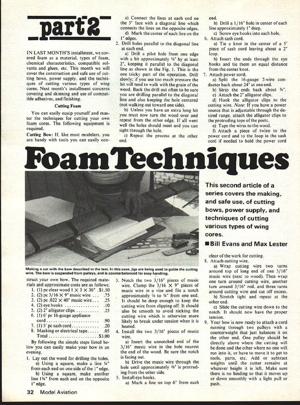
This second article of a series covers the making, and safe use, of cutting bows, power supply, and techniques of cutting various types of wing cores.
- Bill Evans and Max Lester
Cutting Foam
You can easily equip yourself and master the techniques for cutting your own foam cores. The following equipment is required.
Cutting Bow: If, like most modelers, you are handy with tools you can easily construct your own bow. The required materials and approximate costs are as follows:
- (1) pc clear wood 1 X 3 X 36" ...... $1.50
- (2) pc 3/16 X 9" music wire ...... .75
- (2) pc .022 X 40" music wire ...... .25
- (2) eye hooks ...... .10
- (2) alligator clips ...... .25
- (1) pc 16-gauge appliance cord ...... .90
- (1) 5' pc sash cord ...... .20
- Masking or electrical tape ...... .05
Total ...... $3.00
By following the simple steps listed below you can easily make your bow in an evening.
- Lay out the wood for drilling the holes.
a) Using a square, make a line 1/4" from each end on one side of the 1" edge. b) Using a square, make another line 1/4" from each end on the opposite 1" edge. c) Connect the lines at each end on the 3" face with a diagonal line which connects the lines on the opposite edges. d) Mark the center of each line on the 1" edges.
- Drill holes parallel to the diagonal line at each end.
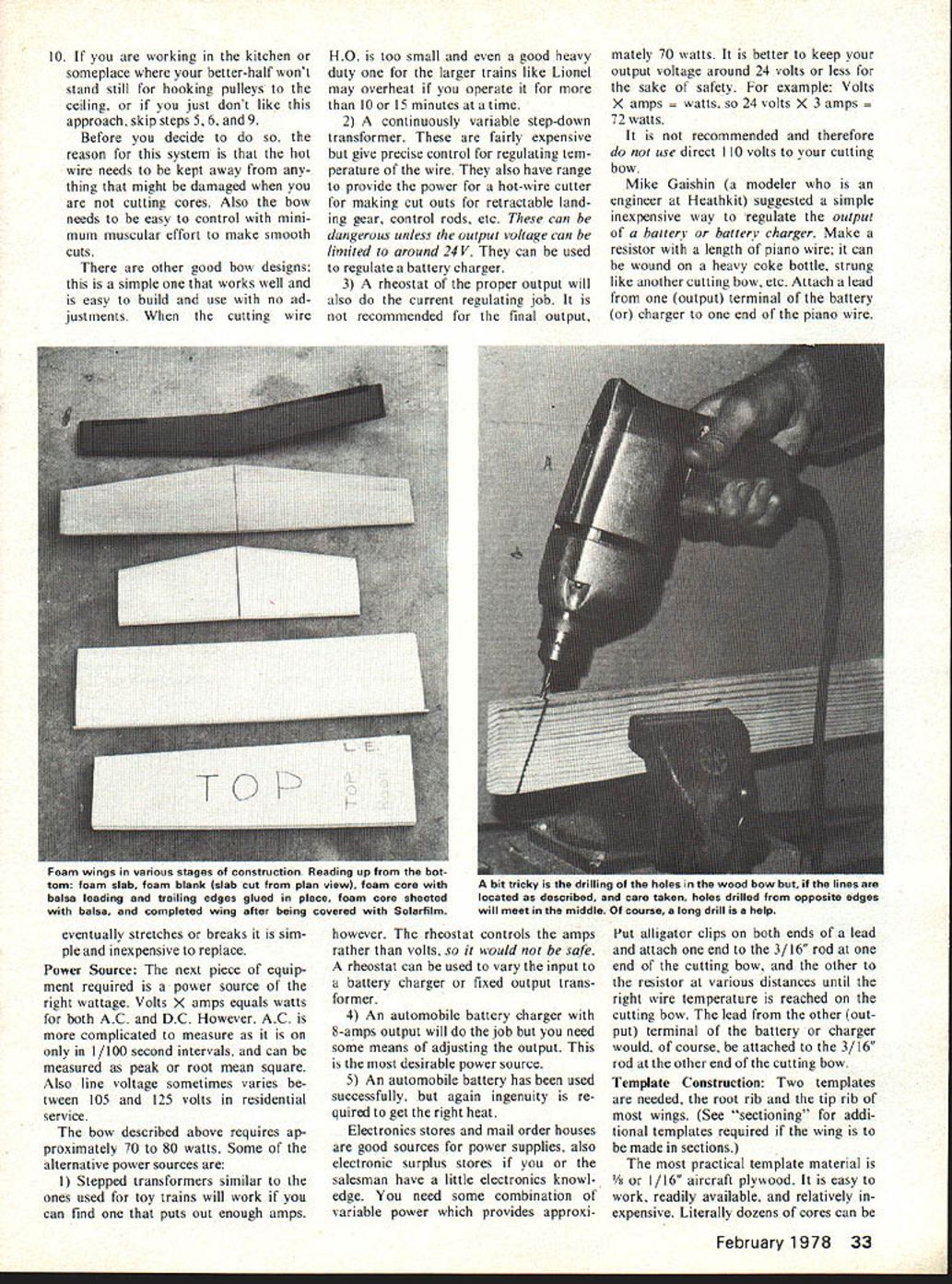
a) Drill a pilot hole from one edge with a bit approximately 1/8" by at least 2", keeping it parallel to the diagonal line as shown in the Fig. 1. This is the one tricky part of the operation. Drill slowly; if you use too much pressure the bit will tend to walk with the grain of the wood. Back the drill out often to be sure you are drilling parallel to the diagonal line and also keeping the hole centered (not walking out toward one side). b) Unless you have an extra long bit you must now turn the wood over and repeat from the other edge. If all went well the holes should meet and you can sight through the hole. c) Repeat the process at the other end.
- Notch the two 3/16" pieces of music wire. Clamp the 3/16 X 9" pieces of music wire in a vise and file a notch approximately 1/8" to 1/4" from one end. It should be deep enough to keep the cutting wire from slipping off. It should also be smooth to avoid nicking the cutting wire which is otherwise more likely to break under tension when it is heated.
- Install the two 3/16" pieces of music wire.
a) Insert the unnotched end of the 3/16" music wire in the hole nearest the end of the wood. Be sure the notch is facing out. b) Drive the music wire through the hole until approximately 3/8" is protruding from the other side.
- Install eye hooks.
a) Mark a line on top 6" from each end. b) Drill a 1/16" hole in center of each line approximately 1" deep. c) Screw eye hooks into each hole.
- Attach sash cord.
a) Tie a knot in the center of a 5' piece of sash cord leaving about a 2" loop. b) Insert the ends through the eye hooks and tie them an equal distance from the center knot.
- Attach power cord.
a) Split the 16-gauge 2-wire conductor back about 24" at one end. b) Strip the ends back about 3/4". c) Attach the 2 alligator clips. d) Hook the alligator clips to the cutting wire. Note: If you have a power source that is adjustable through the desired range, attach the alligator clips to the protruding tops of the posts. e) Tape the wires to the wood. f) Attach a piece of twine to the power cord and to the loop in the sash cord if needed to hold the power cord clear of the work for cutting.
- Attach cutting wire.
a) Wrap cutting wire two turns around top of long end of one 3/16" music wire (next to wood). Then wrap one turn around cutting wire, another turn around 3/16" rod, and three turns around cutting wire and cut off excess. b) Stretch tight and repeat at the other end. c) Slide the cutting wire down to the notch. It should now have the proper tension.
- Your bow is now ready to attach a cord running through two pulleys with a counterweight that just balances it on the other end. One pulley should be directly above where the cutting will be done and the other where no one will run into it, or have to move it to get to tools, parts, etc. Add or subtract weights until the cutter remains at whatever height it is left. Make sure there is no binding so that it moves up or down smoothly with a light pull or push.
- If you are working in the kitchen or someplace where your better-half won't stand still for hooking pulleys to the ceiling, or if you just don't like this approach, skip steps 5, 6, and 9.
Before you decide to do so, the reason for this system is that the hot wire needs to be kept away from anything that might be damaged when you are not cutting cores. Also the bow needs to be easy to control with minimum muscular effort to make smooth cuts.
There are other good bow designs: this is a simple one that works well and is easy to build and use with no adjustments. When the cutting wire H.O. is too small and even a good heavy duty one for the larger trains like Lionel may overheat if you operate it for more than 10 or 15 minutes at a time.
Power Source
The bow described above requires approximately 70 to 80 watts. Some of the alternative power sources are:
- Stepped transformers similar to the ones used for toy trains will work if you can find one that puts out enough amps. H.O. is too small and even a good heavy duty one for the larger trains like Lionel may overheat if you operate it for more than 10 or 15 minutes at a time.
- A continuously variable step-down transformer. These are fairly expensive but give precise control for regulating temperature of the wire. They also have range to provide the power for a hot-wire cutter for making cut outs for retractable landing gear, control rods, etc. These can be dangerous unless the output voltage can be limited to around 24 V. They can be used to regulate a battery charger.
- A rheostat of the proper output will also do the current regulating job. It is not recommended for the final output, however. The rheostat controls the amps rather than volts, so it would not be safe. A rheostat can be used to vary the input to a battery charger or fixed output transformer.
- An automobile battery charger with 8-amps output will do the job but you need some means of adjusting the output. This is the most desirable power source.
- An automobile battery has been used successfully, but again ingenuity is required to get the right heat.
Electronics stores and mail order houses are good sources for power supplies, also electronic surplus stores if you or the salesman have a little electronics knowledge. You need some combination of variable power which provides approximately 70 watts. It is better to keep your output voltage around 24 volts or less for the sake of safety. For example: Volts X amps = watts, so 24 volts X 3 amps = 72 watts.
It is not recommended and therefore do not use direct 110 volts to your cutting bow.
Mike Gaishin (a modeler who is an engineer at Heathkit) suggested a simple inexpensive way to regulate the output of a battery or battery charger. Make a resistor with a length of piano wire; it can be wound on a heavy coke bottle, strung like another cutting bow, etc. Attach a lead from one (output) terminal of the battery (or charger) to one end of the piano wire. Put alligator clips on both ends of a lead and attach one end to the 3/16" rod at one end of the cutting bow, and the other to the resistor at various distances until the right wire temperature is reached on the cutting bow. The lead from the other (output) terminal of the battery or charger would, of course, be attached to the 3/16" rod at the other end of the cutting bow.
Template Construction
Two templates are needed, the root rib and the tip rib of most wings. (See "sectioning" for additional templates required if the wing is to be made in sections.)
The most practical template material is 1/16" or 1/8" aircraft plywood. It is easy to work, readily available, and relatively inexpensive. Literally dozens of cores can be cut from the plywood template so there is little reason to go to 1/16" formica or 20-gauge aluminum for durability as they are harder to work.
The first step is to decide on the thickness of the material to be used for sheeting.
Trace the ribs from a kit or from the plans allowing for any difference in thickness of the sheeting material. Locate the chord line and draw it from the L.E. to T.E. on both sides of the template.
Cut a little outside the outline and sand carefully to the line, using a very fine sandpaper for finishing. 280 wet-or-dry used dry is good. A vibrating sander or block hand sander should be used to insure that there are no dips or bumps. The hot wire will faithfully reproduce any irregularities so don't hesitate to throw away a template if it isn't perfect.
The template will be held in place by nails pushed through holes in the templates into the foam.
Next, cutting speed marks must be laid out on each template. Cutting is a two-person job. One person will set the pace calling out the numbers on the marks, and the other will maintain the same relative position by the matching numbers on his or her end. The marks should be about 1/2" apart, equally spaced from the T.E. to the chord line at the L.E. on the top and on the bottom. Number the marks consecutively, starting with #1 at the first mark nearest the L.E. For tapered wings, the marks on the tip template must be proportional to those on the root template. There are two fairly easy ways to do this. First (and best), using a pair of dividers you can divide the distance, starting at the T.E., into the same number of equal spaces as those on the root. At the appropriate number, the spacing can then be divided in half and correspond to the root template. You can get close to the same results by using the right combination of scales on engineers and architects scales. The spaces should be numbered consecutively and should be identically marked and numbered on each side.
Label the top of the template on both sides. Hold the templates together in the proper relative position to cut the right wing panel and label the outsides right. Now hold them together in the proper relative position for the left panel and label the outside left.
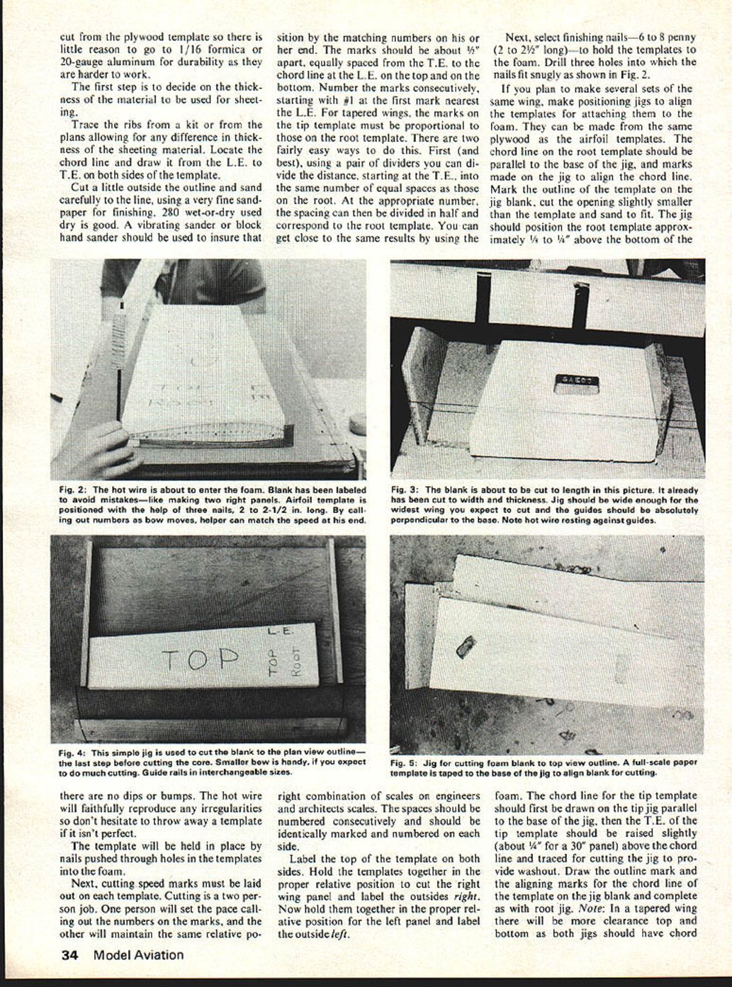
Next, select finishing nails—6 to 8 penny (2 to 2-1/2" long)—to hold the templates to the foam. Drill three holes into which the nails fit snugly as shown in Fig. 2.
If you plan to make several sets of the same wing, make positioning jigs to align the templates for attaching them to the foam. They can be made from the same plywood as the airfoil templates. The chord line on the root template should be parallel to the base of the jig, and marks made on the jig to align the chord line. Mark the outline of the template on the jig blank, cut the opening slightly smaller than the template and sand to fit. The jig should position the root template approximately 1/8" to 1/4" above the bottom of the foam.
The chord line for the tip template should first be drawn on the tip jig parallel to the base of the jig, then the T.E. of the tip template should be raised slightly (about 1/4" for a 30" panel) above the chord line and traced for cutting the jig to provide washout. Draw the outline mark and the aligning marks for the chord line of the template on the jig blank and complete as with root jig. Note: In a tapered wing there will be more clearance top and bottom as both jigs should have chord lines at the same height.
Simple jigs should also be made to cut foam blocks into blanks of the proper thickness, length and top view plan prior to cutting the core.
A jig for cutting the length is shown in Fig. 3. It should be wide enough for the widest wing you expect to cut and the cutting guides should be absolutely perpendicular to the base.
A jig for cutting the blank thickness is shown in Fig. 4. It should be wide enough for the longest panel you plan to cut. The height of the cutting guide rails should be approximately 1/4 to 1/2 inch deeper than the particular wing panel cross section to be cut from the foam blank with this set of rails. Holes just large enough to provide a very snug fit for the positioning dowels should be drilled through the base and into the cutting guide rails. The dowels should be removable in order to permit marking the hole location on additional guide rails for other wing thicknesses later on. Guide rails should be perfectly straight and smooth to assure smooth square blanks.
The foam blank should be cut to the top view plan (top view outline) of the wing before you cut the core. Make a full scale paper template of the top view plan of the wing in order to lay out and cut the foam blank. A jig to cut the plan form of the blank is shown in Fig. 5. The width should allow for the longest panel you plan to cut (turned at the necessary angle in the case of a tapered wing). The end of the cutting guides should be exactly perpendicular to the base. A full scale paper template of the wing plan can be taped to the base of the jig to align the foam blank for cutting, and guide strips tacked in place to position it.
The blocks of foam should be square at all intersecting surfaces. If not, the block must be cut to square them. (A possible exception would be that the ends of the block could be at an angle fore and aft to the L.E. and T.E., but ends should still be vertical to top and bottom of block.)
Prior to cutting the core the blanks should be cut to thickness, length and top view plan outline.
Cutting The Core: Once the wing blank is cut, the core can be cut as follows:
1) First label the blank with a very soft pencil or a felt-tip marking pen. L.E. Top—for leading edge, top side of the wing. Right—for right panel. Label the other blank L.E. Top Left. Be sure that the correct edge is labeled L.E. For tapered wings; match the blanks in position for assembled wing to make a final check. It is far too easy accidentally to cut two left or two right panels.
2) Mark the chord line on the block at each end if you did not make alignment jigs. Check to be sure they are at the same height on each end and parallel to the bottom of the blank. On a tapered wing use the root template to mark the proper height of the chord line to assure proper clearance top and bottom.
3) Align the root template chord line to the chord line on the root of the blank or align with the alignment jig. Be sure that the T.E. of the template extends the proper distance beyond the T.E. of the foam. Check to be sure the side of the template, right or left, corresponds to the label on the top of the blank and that top on the template is up.
4) Carefully push the nails through the holes in the template into the foam perpendicular to the side of the template.
5) Align the tip template chord line to the chord line scribed on the blank at the L.E. and about 1/4 inch above the chord line on the blank at the T.E., or align with a tip template jig.
6) Carefully push the nails through the holes in the template into the blank. Remove the positioning jigs if any were used. Cutting is a two-person job. One person, the caller, will control the speed of the cut and call out the numbers as the wire passes them. The follower will keep his end of the wire at the speed needed to pass the same numbers on the tip and at the same instant as they are called by the caller.
7) The caller should know the approximate speed at which the foam will melt for cutting from experience gained in cutting the blanks from the block. If the cut is too fast the wire will lag in the center and the wing will be rough and not a true copy of the template airfoil.
If the cut is too slow the foam will be melted too much and again the surface will be rough and not a true copy.
It is a good idea to practice on some scrap first. At the correct temperature the residue from cutting will slowly burn off the wire in a thin grey smoke.
8) Position the blank on a flat surface under the suspended bow cutter. Seats should be provided at either end for the two cutters; preferably, the foam should be at about eye level for ease of control. Weights should be placed on the foam to hold it steady during cutting. Three 1/2-lb. weights should do.
9) The caller will turn on the bow and test the temperature with a piece of scrap after it warms up. The caller will then call "to template" and each person will grasp his or her end of the rod to the cutting bow a little above the hot wire, and bring the wire to the top of the protruding T.E. of the template.
10) The caller will call "ready to cut" and the follower will respond "ready" when he is steady and comfortable.
11) The caller will call "enter now" as the wire contacts the foam on his side.
12) The caller calls the numbers as the wire reaches the mark and the follower matches speed passing the same numbers at the same time.
13) As the caller approaches the leading edge, he calls "slow" and slows down enough to let the center of the wire catch up so that it comes out of the foam as a straight wire. The caller says "out" as he comes out of the leading edge and the follower should come out at almost the same instant. Once a cut is begun, do not stop. You may slow down or speed up. Stopping will produce grooves. Best results will come from a continuous cut. Note: The authors recommend a flat surface on the T.E. for a T.E. spar and on the L.E. for a L.E. spar. It makes the wing much stronger and easier to sheet. This will be described in detail in the next issue.
14) Finally bring the wire back and repeat the process to cut the bottom side of the core, starting underneath the T.E. of the template. If your first core isn't perfect, don't be discouraged; a little practice will take care of the problem. In the meantime, if the core isn't too bad, there are ways to salvage it, as will be discussed in the next issue.
Sectioning
The hot-wire method of cutting has the limitation that all cuts must be in a straight line. Wings with more than one taper angle on either the L.E. or T.E. must be cut in sections and glued together. Follow the same procedure for each section as described for cutting a wing panel.
The tip template of the inboard section is also the root template for the outboard section. Each additional section requires one additional template for the tip of that section.
It is also necessary to cut very long wings in sections due to limitations on the tension necessary to keep the wire straight and on power for uniform heating of the wire.
Dihedral Angle Cutting
One of the simplest ways of cutting the dihedral angle for a two-piece wing is to raise the tip the prescribed height (the height can be calculated if only the angle is given) and then make a vertical cut at the root of the panel. This can best be done after cutting the core, but with the core still in the blank. It can be done before sheeting with the end-cutting jig, or after sheeting with a saw and/or a sanding block and the end-cutting jig.
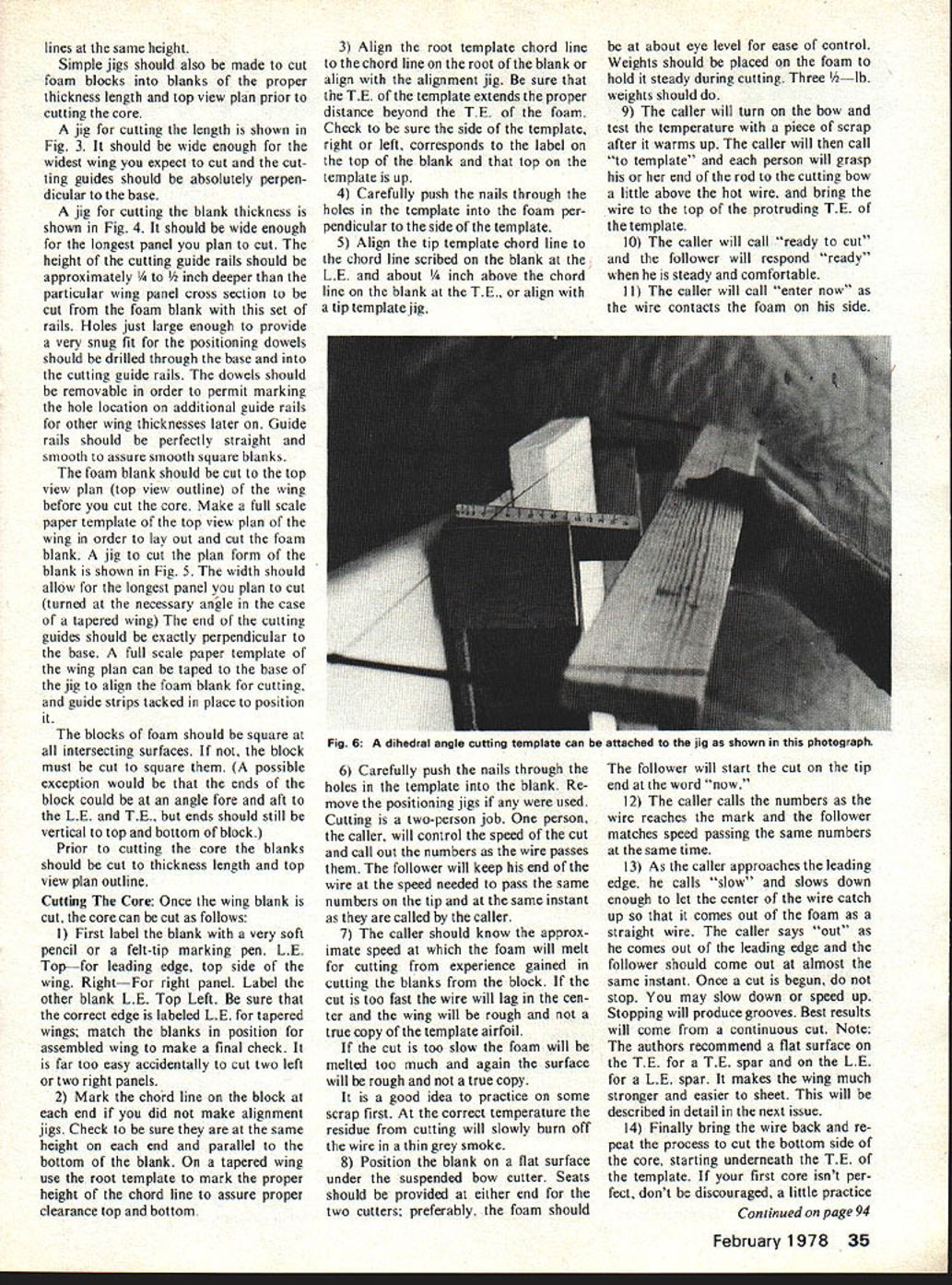
It can also be done with a dihedral-angle cutting template. The angle-cutting template can be attached to the foam blank with nails pressed into the foam or it can be attached to a cutting jig (see Fig. 6).
The template angle is one half the complement of the total desired angle, as both surfaces must be cut to match the cross sections at the joint. For example, if a ten-degree angle is required, the template angle will be (90° - 10°/2) or 85°.
Regardless of the method, it should be done systematically to avoid cutting the angle at the wrong end, or in the wrong direction.
For two-panel wings (right and left), be sure that the top is up and that cut is at the root of the panel (except for gull wings).
To cut the angle for the outboard section of a polyhedral wing, be sure the top is up and the cut is at the outer end (tip) of the inboard section, and at the root of the outboard section (except for gull wings).
The same principles apply if the core was cut as a complete right or left panel and then sectioned for the polyhedral angle.
To be continued.
Transcribed from original scans by AI. Minor OCR errors may remain.

