
The Focke-Wulf Stosser
Editor's Note: This is not "just" a rubber model. It is one of the most realistic scale jobs we have ever seen fly. The article is masterful for its background and techniques, comparable to Bill Noonan's, and deserving of attention by all modelers regardless of their prime interest. Articles like this one cross party lines, so to speak, and are to be treasured for their excellence.
Tom Nallen
Finally, with eyes straining, I could no longer see the Stosser. Almost directly overhead the circling speck that was my model had disappeared against a patch of blue in a sky dotted with light, puffy cumulus clouds. She was gone. The occasional flashes of sunlight off her silver finish came down no more.
We were at the first Flying Aces Club Nats at the Johnsville Naval Air Development Center in Warminster, Pennsylvania. This gathering of rubber-scale types, probably the greatest in decades, filled the lobby, bouncy air with models of all kinds and transformed the scene into a scale buff's paradise. I had followed the Stosser as she wheeled in a light drift, watching her climb higher and higher for 25 minutes. Now, searching an empty sky, a number of thoughts tumbled through my mind: Where would she come down? How do you chase 'em when they go straight up? How long, I wondered, would she fly?
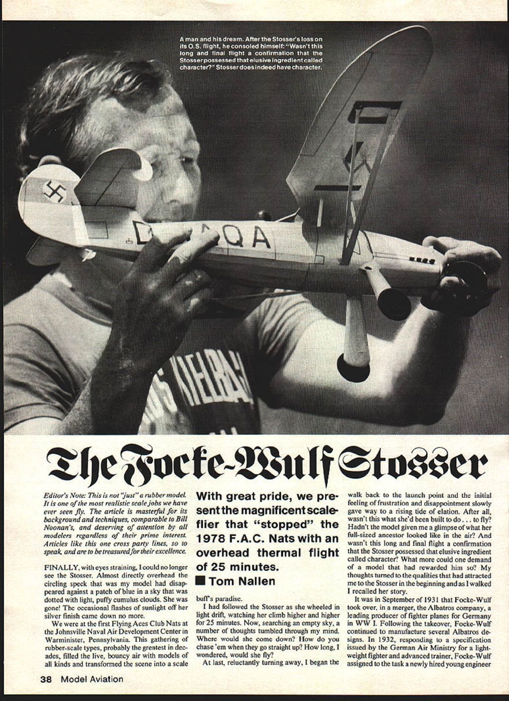
At last, reluctantly turning away, I began the walk back to the launch point and the initial feeling of frustration and disappointment slowly gave way to a rising tide of elation. After all, wasn't this what she'd been built to do — to fly? Hadn't the model given me a glimpse of what her full-sized ancestor looked like in the air? And wasn't this long and final flight a confirmation that the Stosser possessed that elusive ingredient called character? What more could one demand of a model that had rewarded him so? My thoughts turned to the qualities that had attracted me to the Stosser in the beginning and as I walked I recalled her story.
History
In September 1931 Focke-Wulf took over, in a merger, the Albatros company, a leading producer of fighter planes for Germany in World War I. Following the takeover, Focke-Wulf continued to manufacture several Albatros designs. In 1932, responding to a specification issued by the German Air Ministry for a lightweight fighter and advanced trainer, Focke-Wulf assigned the task to a newly hired young engineer named Kurt Tank — his first work at the company.
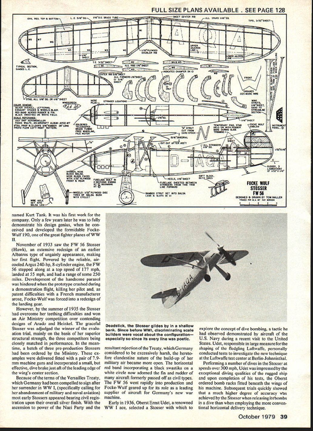
Only a few years later he had fully demonstrated his design genius and had conceived and developed the formidable Focke-Wulf 190, the great fighter plane of WWII. November 1933 saw the Fw 56 Stosser (Stosser Hawk), an extensive redesign of an earlier Albatros type, make its first flight. Powered by the reliable air-cooled Argus 240-hp 8-cylinder engine, the Fw 56 had a top speed of 177 mph, a landing speed of 55 mph, and a range of some 250 miles.
Development of the handsome parasol was hindered when the prototype crashed during a demonstration flight, killing the pilot. Patent difficulties with a French manufacturer arose and Focke-Wulf was forced to redesign the landing gear. However, by the summer of 1935 the Stosser, having overcome its teething difficulties, won the Air Ministry competition over contending designs by Arado and Heinkel. The graceful Stosser was adjudged the winner mainly on the basis of superior structural strength; the three competitors were closely matched in performance. A batch of three pre-production Stossers was ordered by the Ministry. The examples delivered were fitted with a pair of 7.9 mm machine guns and incorporated a small, effective dive brake just aft of the leading edge of the wing center section.
Because, under the terms of the Versailles Treaty, Germany was compelled after World War I to abandon military and naval aviation, early Stossers appeared bearing civil registration upon an overall silver finish. With the ascendancy to power of the Nazi Party and the resultant rejection of the Treaty of Versailles by Germany, the hitherto clandestine nature of the build-up of military air power became open. A horizontal red band incorporating a black swastika in a white circle now adorned the fin and rudder of aircraft formerly passed off as civil types. The Fw 56 went rapidly into production and Focke-Wulf became a leading supplier of aircraft to Germany's new war machine.
Early in 1936 Oberst Ernst Udet, a renowned World War I ace, selected the Stosser to explore the concept of dive-bombing, a tactic observed during a recent visit to the United States. Udet, influential in shaping the fledgling Luftwaffe, personally conducted tests at the Luftwaffe test center, Berlin-Johannisthal. Performing a number of dives in the Stosser at speeds over 300 mph, Udet was impressed with the exceptional diving qualities of the rugged ship. Upon completion of the tests the Oberst ordered bomb racks fitted beneath the wings of his machine. Subsequent trials quickly showed that a much higher degree of accuracy was achieved by the Stosser when releasing its bombs in a dive than when employing the more conventional horizontal delivery technique.
The convincing performance of the sturdy Stosser in the bombing trials resulted in the decision to adopt the dive bomber as a major weapon in the Luftwaffe's arsenal. Development of the more powerful, all-metal Junkers Ju 87 Stuka was undertaken, resulting in a machine that was to write a new chapter in the history of aerial warfare. The infamous bent-winged Stuka, appearing as airborne artillery working in concert with highly mobile and powerful ground forces, became symbolic of the Blitzkrieg (Lightning War) with which Hitler opened WWII.
Although the Stosser wasn't suited to play a major combatant role in WWII, Focke-Wulf produced over 1,000 of the type. Serving mainly as an advanced trainer at Luftwaffe fighter and dive-bomber pilot schools, the fully aerobatic and tough machine was a favorite among young pilots. From early production runs several Stossers were provided as mounts for crack German aerobatic fliers, creating a favorable impression at air shows and trials. The skilled German stunt flier Gerd Achgelis made several memorable appearances in the U.S. during the mid-1930s, thrilling National Air Race crowds.
It is no more possible not to stare at the Stosser every time it flies than it is to eat just one potato chip. Multi-stringered fuselage, inverted in-line cowl, sweep-back parasol wing, and flowing curves everywhere — picture flier.
Suitability as a Model Subject
As a subject for a rubber-powered flying scale model, the Focke-Wulf design has a lot to commend it. The old aviation adage that a plane that looks right, flies right, is borne out by the Stosser. The combination of the gracefully contoured swept wing, highly distinctive tail group, and a fuselage and landing gear of smoothly flowing yet functional lines, come together to offer one of the most attractive parasol-type airplanes ever to come off a drawing board. A soft silver finish setting off the black registration lettering caps the Stosser's appeal.
Construction
Construction, while not difficult, employs sheet fill between stringers in much of the forward fuselage and requires a little more time on the part of the builder. The finished product, however, rewards this slight extra effort with a very rugged model, one that will come through relatively unscathed in prangs that would bench a more lightly constructed flying machine. At an all-up flying weight of about 3 oz., the Stosser is heavy enough to groove well in flight, yet sensitive enough in good air to hitch a ride in passing thermals.
The fuselage is built in two main parts to accommodate the landing gear installation and to facilitate shaping the fuselage at the radius just aft of the engine cowling. The radius simulates the cooling-air exit from the engine compartment and is a distinctive feature of the Stosser.
Build the fuselage sections using the familiar keel-and-former method. Stringers are laid on alternately, side to side, using care to maintain alignment. Use stringers that are firm but light. Cracking a too-soft stringer in handling the finished model can be avoided by careful wood selection; yet heavy stringers that shoot the weight of the model up sharply should be avoided. It's a kind of tight-rope that rubber scale modelers should learn to walk.
Before the final few upper forward fuselage stringers go into place the wire cabanes are installed. The forward cabane is sewn with thread to its mounting former and the rear cabane is secured to its former via small balsa blocks grooved to fit the wire. Baking soda and cyanoacrylate are used to fix the cabanes in place.
The entire engine cowling and forward fuselage are sheet-filled to the extent shown on the plan. The balsa used for fill should be soft and very light 1/16" sheet. Cut pieces to fit between the stringers, former to former. Only fit the sheet pieces deeply enough to allow secure cementing and when all sheet filling has been completed, trim away excess material with a sharp blade. When sanding the filled sections to final shape, exercise care to avoid scalloping the surface.
The cockpit shape is determined by short pieces of 1/16" square running from former D to the point on the next lower stringer, as shown on the plan. Note that the cockpit sides have a curved upper radius that is 1/16" square sanded to shape and cemented in place.
Landing gear legs are based on 3/32" square bamboo struts. The fairings are shaped of light sheet balsa with the bamboo struts recessed into a groove in the leg. About 3/4" of the bamboo strut extends above the top of the fairing and fits a groove cut into the front fuselage former. The bamboo landing gear works out very well: strength and durability are remarkable. The heavier weight and tendency of long wire gear to bend made bamboo a preferable choice for the Stosser.
The engine cowling was covered on my model by laying on wet 3/4"-wide tissue strips, brushing dope through the tissue onto the wood. Begin at the bottom center of the structure and work your way around it, overlapping the strips slightly as you go. Cover the fuselage from the rear working forward. Strips of tissue wide enough to cover five or six stringers at a time can be used, and the strips should extend about one inch onto the forward planking. Begin on the upper rear turtledeck, aft of the cockpit, working down the sides until the bottom can be covered with a single strip. Finish by covering the planked forward areas in the same manner used to cover the cowling. The balsa landing gear leg fairings are tissue covered.
Wing, tail surfaces, and fuselage are sprayed with a fine water mist to shrink the tissue. When dry, brush on three coats of thin nitrate dope (70%) to all tissue-covered areas, except for the tail surfaces, where a couple of coats will suffice. On the planked areas only, sand lightly between coats using worn-out fine sandpaper, and apply an additional three coats of dope, sanding between each. Finally, skim lightly over the entire fuselage with the worn-out sandpaper, and touch lightly on the leading and trailing edges of the flight surfaces.
Mount the landing gear into the slots in the front fuselage former, and after very carefully checking alignment, cement the cowling to the fuselage. Fit the cabanes into the tubing pieces in the wing. Using a jig of sheet balsa made from the side view of the plan, set the angle of incidence of the wing. When the wing is correctly aligned on the cabanes, turn the model over and, carefully packing baking soda into the tubing around the cabanes, fix them with cyanoacrylate. Add balsa fairings to the cabanes by cementing the diagonal cabane member in place. Fabricate the wing struts and prepare the struts and cabanes for painting by sealing the balsa's grain. A suitable sealer is easily made by adding talcum powder to dope. Several sanded coats will do the trick.
Carefully trim and fit the wing struts to the wing and fuselage. At the attachment points, cut away a small piece of tissue to get a solid wood-to-wood joint.
Add the exhaust stacks and the tail skid and seal for painting. To very thin nitrate dope, add a very small amount of aluminum bronzing powder (I used Luco brand). This powder is available in many art supply stores, is inexpensive, and a little goes a long way. Using a Badger internal-mix airbrush, the coverage is excellent and the bright build-up of three or four coats is minimal. Experiment with paint and spray pattern on another object before turning to the model. Between applications, touch up with the worn-out sandpaper any areas that may need it.
Registration lettering, control-surface and panel cutlines were cut from black tissue. The red band and black swastika on the fin and rudder are cut from tissue. The tissue was applied with a spray adhesive called Spra-Mount (a 3M product). The white disc that forms the field for the swastika was masked prior to applying the silver paint to the fin and rudder. An advantage of the spray adhesive is that tissue trim may be easily repositioned after the initial mounting, if necessary.
The fairing at the fuselage/landing gear junction was done with GE's RTV silicone rubber. The material is available in silver and can be obtained at most hardware stores. It can be easily formed with wet fingertips and sets up in a fairly short time. The rubber won't take paint, but using the spray adhesive the fairing can be tissue covered, then painted.
A free-wheeling Paulownia prop of 9" diameter was fitted into a spinner turned from balsa. The free-wheeling device was a piece of brass tubing with a ramp-type notch cut into the end, the latching method being similar to that used on plastic propellers. Two loops of 3/16" rubber about 28 inches long power the ship.
During initial flight tests, the stabilizer was held in place with a rubber band to allow for shimming of the stab to optimize glide trim. First hand-glides were made without the prop and with clay added to the nose to bring the CG to the point shown on the plan. One thickness of matchbook paper under the leading edge of the stab was required to give the desired glide. The stab was cemented into place and prop and rubber installed. A little clay was placed to compensate for the rubber weight aft, and was packed just inside the nose opening to maintain the original balance point.
No thrust offsets were built into the model and first powered flights showed that a shim of 1/8" balsa, inserted between the front of the nose block and the nose former, provided the down-thrust needed. No side-thrust was used and the model flew well under power and circled right in the glide. If desired, 4–5 degrees of down-thrust could be built into the nose block.
Early flights of 40 to 60 seconds were regularly achieved, but a glide turn approaching a bank appeared to be bringing the Stosser down early. Rudder tweaking didn't help, nor did application of side-thrust. Careful scrutiny of the wing from the rear showed an almost imperceptible excess of wash-out present in the right wing panel over that in the left panel. Cutting away the rear wing strut (left panel when viewed from the rear), a tiny piece of 1/32" sheet was inserted at the strut/wing junction, jacking up that trailing edge slightly. The glide turn then flattened out nicely.
Flight Testing and Competition
Before this fix the Stosser had about 50 flights in her log and had been flown in two Flying Aces Club meets at Durham, Conn., without distinguishing herself. She was fun to fly, however, and exhibited a great deal of realism in the air. Because the model had proven to be a dependable flier in high winds we decided to bring her along to Johnsville as a second entry in FAC scale and for competition in AMA scale, also a scheduled event.
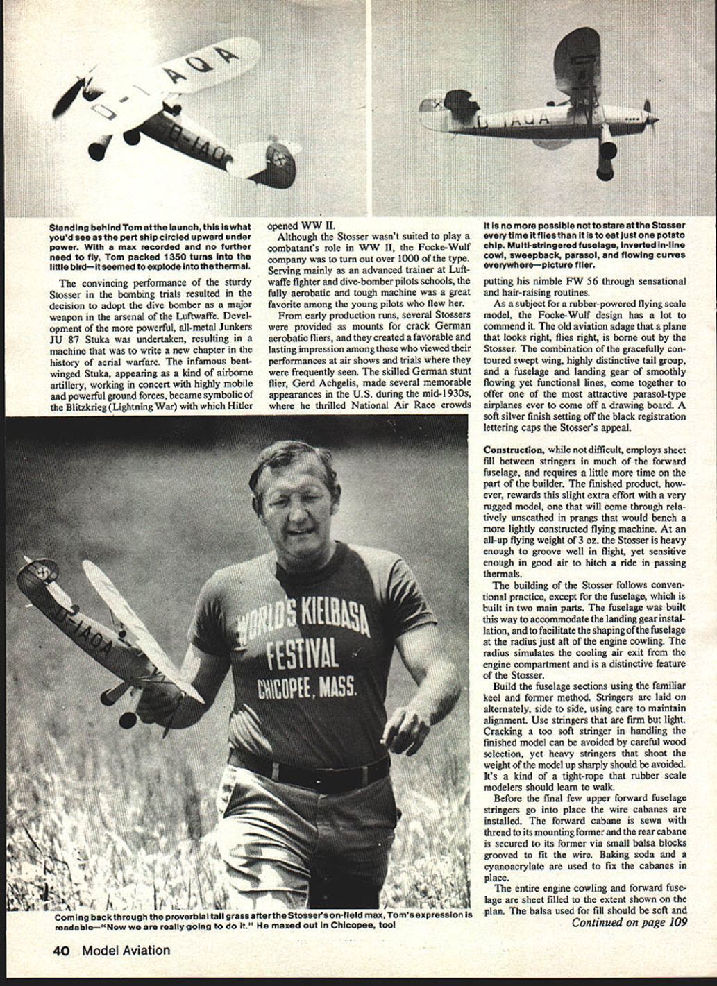
Our first flight at the FAC Nats was a check hop to determine that flight trim hadn't changed since our last outing. The succeeding flight was an official and found the Stosser wheeling purposefully in a thermal for almost four minutes. With a max recorded, no further flights were required (under FAC rules), but with the superb conditions prevailing two subsequent flights were made. A routine and uneventful flight was put up, and a little later, about 2:00 p.m., the ship was readied for what was to be her last flight. The rubber motor was wound to a new high — 1,350 turns. Exploding off the launch into a thermal, the Stosser never stopped climbing until she disappeared high overhead, finally yielding a recorded overhead thermal flight of 25 minutes.
For those who might build the Fw 56 for AMA scale, the three-views upon which this design was based may be found in the August 1967 issue of Aeromodeller magazine. The drawings by Ian Stair are excellent and a 5x scale was used. Focke-Wulf, Aircraft Album No. 7 (Arco) contains photos and some historical background data.
For modelers who have difficulty locating bamboo, a supply of 1" long pieces, for which a number of uses may be found, is available for $2.50 P&P from Mr. Bert Pond, 128 Warren Terrace, Longmeadow, MA 01106.
Special thanks are extended to Dick Benjamin, FAC, who took time out from his own flying activities at Johnsville (he lost a fine Rearwin Speedster O.O.S.) to take the photographs accompanying this article.
Transcribed from original scans by AI. Minor OCR errors may remain.

