
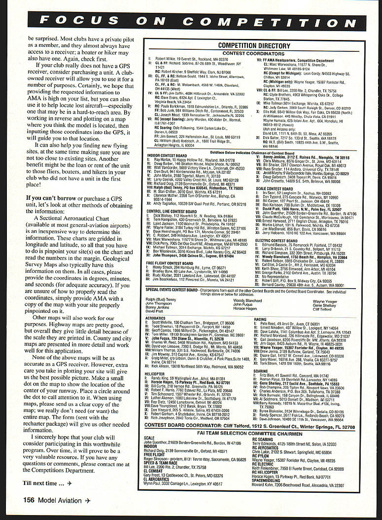
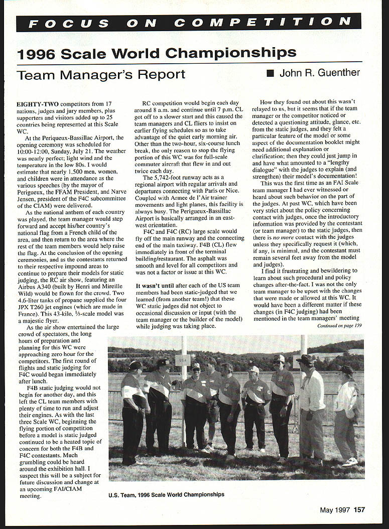
Focus on Competition
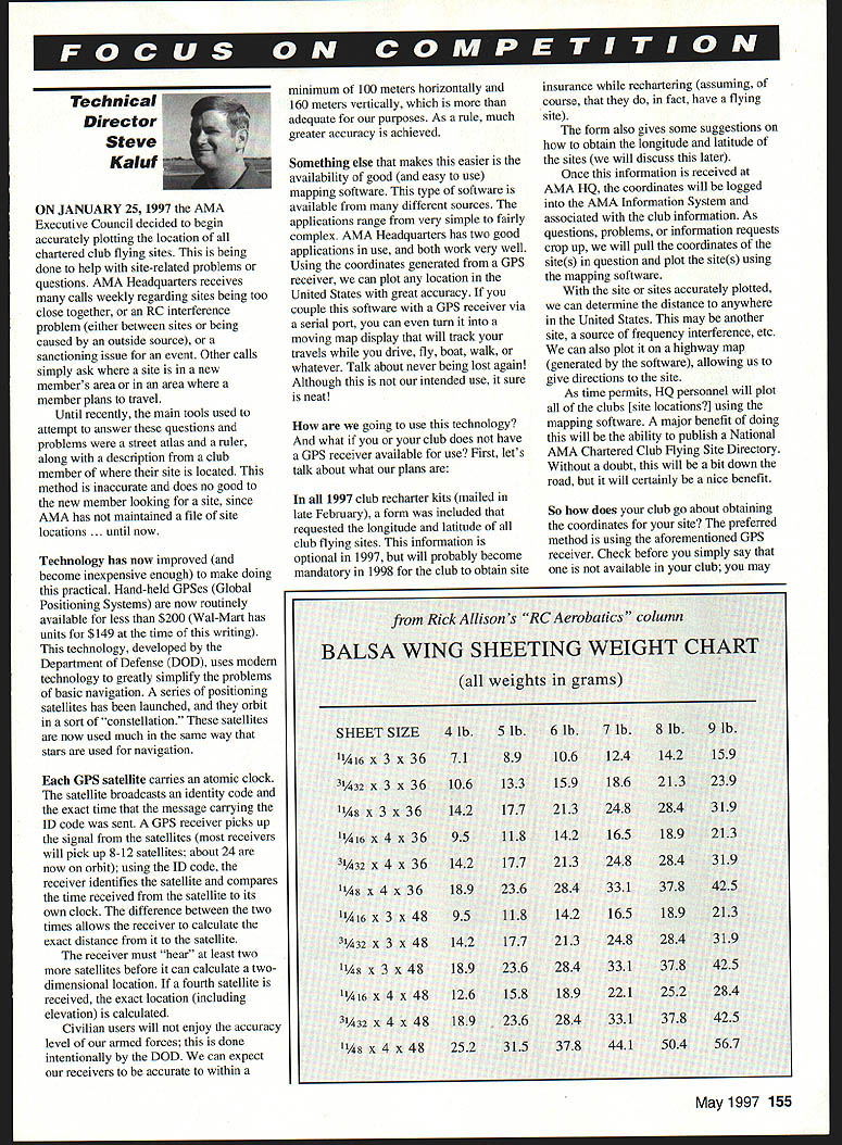
Technical Director Steve Kaluf
On January 25, 1997 the AMA Executive Council decided to begin accurately plotting the location of all chartered club flying sites. This is being done to help with site-related problems or questions. AMA Headquarters receives many calls weekly regarding sites being too close together, RC interference problems (either between sites or caused by an outside source), or a sanctioning issue for an event. Other calls simply ask where a site is in a new member's area or in an area where a member plans to travel.
Until recently, the main tools used to attempt to answer these questions and problems were a street atlas and a ruler, along with a description from a club member of where their site is located. This method is inaccurate and does no good to the new member looking for a site, since AMA has not maintained a file of site locations—until now.
Technology has now improved (and become inexpensive enough) to make doing this practical. Hand-held GPSes (Global Positioning Systems) are now routinely available for less than $200 (Wal-Mart had units for $149 at the time of this writing). This technology, developed by the Department of Defense (DOD), uses modern electronics to greatly simplify the problems of basic navigation. A series of positioning satellites has been launched, and they orbit in a sort of "constellation." These satellites are now used much in the same way that stars are used for navigation.
Each GPS satellite carries an atomic clock. The satellite broadcasts an identity code and the exact time that the message carrying the ID code was sent. A GPS receiver picks up the signal from the satellites (most receivers will pick up 8–12 satellites; about 24 were on orbit at that time). Using the ID code the receiver identifies the satellite and compares the time received from the satellite to its own clock. The difference between the two times allows the receiver to calculate the exact distance from it to the satellite. The receiver must "hear" at least two more satellites before it can calculate a two-dimensional location. If a fourth satellite is received, the exact location (including elevation) is calculated.
Civilian users will not enjoy the accuracy level of our armed forces; this is done intentionally by the DOD. We can expect our receivers to be accurate to within a minimum of 100 meters horizontally and 160 meters vertically, which is more than adequate for our purposes. As a rule, much greater accuracy is achieved.
Something else that makes this easier is the availability of good (and easy to use) mapping software. Software of this type is available from many different sources. Applications range from very simple to fairly complex. AMA Headquarters has two good applications in use, and both work very well. Using the coordinates generated from a GPS receiver, we can plot any location in the United States with great accuracy. If you couple this software with a GPS receiver via a serial port, you can even turn it into a moving map display that will track your travels while you drive, fly, boat, walk, or whatever. Talk about never being lost again! Although this is not our intended use, it sure is neat!
How are we going to use this technology? And what if you or your club does not have a GPS receiver available for use? First, let's talk about what our plans are.
In all 1997 club recharter kits (mailed in late February), a form was included that requested the longitude and latitude of each club flying site. This information is optional in 1997, but will probably become mandatory in 1998 for the club to obtain site insurance while rechartering (assuming, of course, that they do, in fact, have a flying site).
The form also gives some suggestions on how to obtain the longitude and latitude of the sites (we will discuss this later). Once this information is received at AMA HQ, the coordinates will be logged into the AMA Information System and associated with the club information. As questions, problems, or information requests crop up, we will pull the coordinates of the site(s) in question and plot the site(s) using the mapping software. With the site or sites accurately plotted, we can determine the distance to anywhere in the United States—another site, a source of frequency interference, etc. We can also plot it on a highway map (generated by the software), allowing us to give directions to the site.
As time permits, HQ personnel will plot all of the clubs' site locations using the mapping software. A major benefit of doing this will be the ability to publish a National AMA Chartered Club Flying Site Directory. Without a doubt, this will be a bit down the road, but it will certainly be a nice benefit.
So how does your club go about obtaining the coordinates for your site? The preferred method is using the aforementioned GPS receiver. Check before you simply say that one is not available in your club; you may be surprised. Most clubs have a private pilot as a member, and they almost always have access to a receiver; a boater or hiker may also have one. Again, check first.
If your club really does not have a GPS receiver, consider purchasing a unit. A club-owned receiver will allow you to use it for a number of purposes. Certainly, we hope that providing the requested information to AMA is high on your list, but you can also use it to help locate lost aircraft—especially one that may be in a hard-to-reach area. By working in reverse and plotting on a map where you think the model is located, then inputting those coordinates into the GPS, it will guide you to that location.
It can also help you find new flying sites, at the same time making sure you are not too close to existing sites. Another benefit might be the loan or rent of the unit to those fliers, boaters, and hikers in your club who did not have a unit in the first place.
If you can't borrow or purchase a GPS unit, let's look at other methods of obtaining the information:
- A Sectional Aeronautical Chart (available at most general-aviation airports) is an inexpensive way to determine this information. These charts are gridded in longitude and latitude, so all that you have to do is pinpoint your site(s) on the chart and read the numbers in the margin. Geological Survey maps also typically have this information on them. In all cases, please provide the coordinates in degrees, minutes, and seconds (for adequate accuracy). If you are unsure of how to properly read the coordinates, simply provide AMA with a copy of the map with your site properly pinpointed on it.
- Other maps will also work for our purposes. Highway maps are pretty good, but overall they give little detail because of the scale they are printed in. County and city maps are presented in more detail and work well for this application.
None of the above maps will be as accurate as a GPS receiver. However, the extra care you take in plotting your site will give the best possible picture. Make a small dot on the map to show the location of the center of your runway. Place a circle around the dot to call attention to it. When using maps, please send us a clear copy of the map; we really don't need (or want) the entire map. The form (sent with the recharter package) will give us other needed information.
I sincerely hope that your club will consider participating in this worthwhile program. Over time it will prove to be a very valuable resource. If you have any questions or comments, please contact me at the Competitions Department.
Till next time ...
1996 Scale World Championships
Team Manager's Report John R. Guenther
Eighty-two competitors from 17 nations, judges and jury members, plus supporters and visitors added up to 25 countries being represented at this Scale World Championship.
At the Perigueux-Bassillac Airport, the opening ceremony was scheduled for 10:00–12:00, Sunday, July 21. The weather was nearly perfect: light wind and the temperature in the low 80s. I would estimate that nearly 1,500 men, women, and children were in attendance as the various speeches (by the mayor of Perigueux, the FFAM president, and Narve Jensen, president of the F4C subcommittee of the CIAM) were delivered.
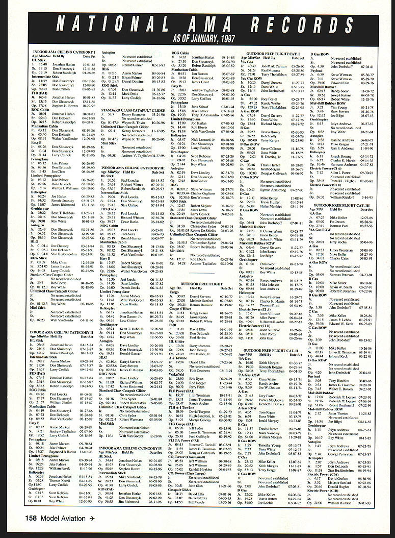
As the national anthem of each country was played, the team manager would step forward and accept his or her country's national flag from a French child of the area, and then return to the area where the rest of the team members would help raise the flag. At the conclusion of the opening ceremonies, and as the contestants returned to their respective impound areas to continue preparing their models for static judging, the RC air show, featuring an Airbus A340 (built by Henri and Mireille Wild) was flown for the crowd. Two 4.6-liter tanks of propane supplied the four JPX T260 jet engines (which are made in France). This 43-kilogram, 3/4-scale model was a majestic flier.
As the air show entertained the large crowd of spectators, the long hours of preparation and planning for this WC were approaching zero hour for the competitors. The first round of flights and static judging for F4C began immediately after lunch.
F4B static judging did not begin for another day, which left the CL team members plenty of time to run and adjust their engines. As with the last three Scale WCs, beginning the flying portion of competition before a model is static judged continued to be a heated topic of concern for both the F4B and F4C contestants. Much grumbling could be heard around the exhibition hall. I suspect this will be a subject for future discussion and change at an upcoming FAI/CIAM meeting.
RC competition began each day around 8 a.m. and continued until 7 p.m. CL got off to a slower start and this caused the team managers and CL fliers to insist on earlier flying schedules so as to take advantage of the quiet early morning air. Other than the two-hour, six-course lunch break, the only reason to stop the flying portion of this WC was for full-scale commuter aircraft that flew in and out twice each day.
The 5,742-foot runway acts as a regional airport with regular arrivals and departures connecting with Paris or Nice. Coupled with Armée de l'Air trainer movements and light planes, this facility is always busy. The Perigueux-Bassillac Airport is basically arranged in an east–west orientation.
F4C and F4C (RC) large scale flew off the main runway and the connecting end of the main taxiway. F4B (CL) flew immediately in front of the terminal building/restaurant. The asphalt was smooth and level for all competitors and was not a factor or issue at this WC.
It wasn't until after each of the U.S. team members had been static-judged that we learned (from another team) that these WC static judges did not object to occasional discussion or input (with the team manager or the builder of the model) while judging was taking place.
How they found out about this wasn't relayed to us, but it seems that if the team manager or the competitor noticed or detected a questioning attitude, glance, etc., from the static judges, and they felt a particular feature of the model or some aspect of the documentation booklet might need additional explanation or clarification, then they could just jump in and have what amounted to a "lengthy dialogue" with the judges to explain (and strengthen) their model's documentation.
This was the first time as an FAI Scale team manager I had ever witnessed or heard about such behavior on the part of the judges. At past WCs, which have been very strict about the policy concerning contact with judges, once the introductory information was provided by the contestant (or team manager) to the static judges, then there is no more contact with the judges unless they specifically request it (which, if any, is minimal, and the contestant must remain several feet away from the model and judges).
I find it frustrating and bewildering to learn about such procedural and policy changes after the fact. I was not the only team manager to be upset with the changes that were made or allowed at this WC. It would have been a different matter if these changes (in F4C judging) had been mentioned in the team managers' meeting.
Focus on Competition
While the RC team members were dealing with their problems, the CL fliers were starting to warm up the competition circle with some top-notch flights.
Jack Sheets and Dale Campbell experienced engine problems during their first flights. Although they received some of the highest flight scores, they were unable to diagnose or correct the mechanical/fuel problems; this made the difference in their own standings and the team's final score.
Stephen Ashby, aided by his wife Kathy, continued to fly relaxed and well-prepared flights.
The CL asphalt area was nearly perfect; only a slight unevenness to the surface. Winds were not much of a factor and had the engine problems been solved early on, Jack and Dale would have surely taken top honors. As it was, the CL team came in third.
It remains a clear fact that the highly detailed early biplane models continue to sway static judges and their scores. Over the past ten years (five Scale WCs), there have been several stages of rule changes to equate the selection of models. At this WC, of 47 RC models, 28 were biplanes, 15 were conventional monoplanes, three were ducted-fan monoplanes, and there was one triplane. Of the biplanes, three were multiengine.
All of the above-mentioned models (except the ducted fans) were eligible for bonuses ranging from a low of 2% for monoplane tail-draggers with tailwheel, up to a whopping 11% for a wing-warping, control-undercambered biplane. Even though the three ducted-fan models had retractable tricycle landing gear, they received 0% bonus.
The bonus system "gimme barrel" has now finally run dry. At the 1998 Scale WC in South Africa, all bonuses will be gone.
The weight limit (for RC only) will rise to 10 kg (22 pounds). Electric-powered models will probably make a stronger appearance, since they will be weighed without their batteries. For flying, the flight K factors will be adjusted by reductions on takeoff, landing, and straight flight. However, increased K factors will be in place for the Figure 8, Descending Circle, and realism in flight. These changes will surely make for a more even playing field for all models and the judging should be less biased.
It seems as though most RC Scale modelers fall into one of two groups: great fliers or great builders. Seldom do we find a person with the character, creativity, skill, and physical ability to combine these two assets. If we do find that person, he is usually already a champion.
As I look back on the 14th Scale WC, it is easy to dismiss or accept the results and what has been written and reported by various publications. What you don't often hear about is how modelers help modelers.
When Dale Campbell was having trouble getting his O.S. engine to run properly, Yasufumi Sugawara, team member from Japan, came over to help him. Yasufumi is the head technician in the technical department of O.S. Engines and knows O.S. engines inside and out. His assistance helped Dale to not only relax a bit but also gave him confidence to compete. Unfortunately, Dale continued to have engine problems during his official flights.
There were hundreds of "personal" stories like this from every WC I have attended.
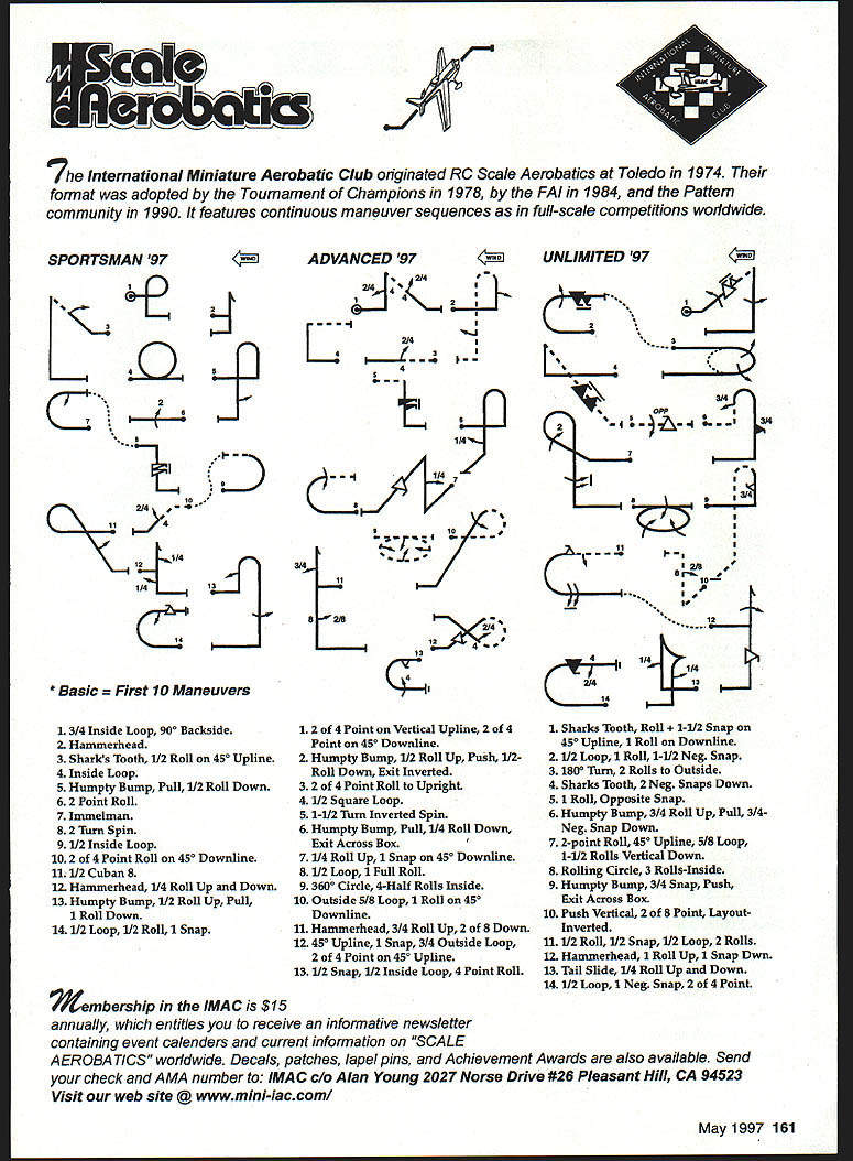
Scale Aerobatics
The International Miniature Aerobatic Club originated RC Scale Aerobatics at Toledo in 1974. Their format was adopted by the Tournament of Champions in 1978, by the FAI in 1984, and by the Pattern community in 1990. It features continuous maneuver sequences as in full-scale competitions worldwide.
SPORTSMAN '97
- 3/4 Inside Loop, 90° Backside.
- Hammerhead.
- Shark's Tooth, 1/2 Roll on 45° Upline.
- Inside Loop.
- Humpty Bump, Pull, 1/2 Roll Down.
- 2 Point Roll.
- Immelmann.
- 2 Turn Spin.
- 1/2 Inside Loop.
- 2 of 4 Point Roll on 45° Downline.
- 1/2 Cuban 8.
- Hammerhead, 1/4 Roll Up and Down.
- Humpty Bump, 1/2 Roll Up, Pull, 1 Roll Down.
- 1/2 Loop, 1/2 Roll, 1 Snap.
ADVANCED '97
- 2 of 4 Point on Vertical Upline, 2 of 4 Point on 45° Downline.
- Humpty Bump, 1/2 Roll Up, Push, 1/2 Roll Down, Exit Inverted.
- 2 of 4 Point Roll to Upright.
- 1/2 Square Loop.
- 1-1/2 Turn Inverted Spin.
- Humpty Bump, Pull, 1/4 Roll Down, Exit Across Box.
- 1/4 Roll Up, 1 Snap on 45° Downline.
- 1/2 Loop, 1 Full Roll.
- 360° Circle, 4 Half Rolls Inside.
- Outside 5/8 Loop, 1 Roll on 45° Downline.
- Hammerhead, 3/4 Roll Up, 2 of 4 Point Down.
- 45° Upline, 1 Snap, 3/4 Outside Loop, 2 of 4 Point on 45° Upline.
- 1/2 Snap, 1/2 Inside Loop, 4 Point Roll.
UNLIMITED '97
- Shark's Tooth, Roll + 1-1/2 Snap on 45° Upline, 1 Roll on Downline.
- 1/2 Loop, 1 Roll, 1-1/2 Roll Snap.
- 180° Turn, 2 Rolls to Outside.
- Shark's Tooth, 2 Negative Snaps Down.
- 1 Roll, Opposite Snap.
- Humpty Bump, 3/4 Roll Up, Pull, 3/4 Negative Snap Down.
- 2-Point Roll, 45° Upline, 5/8 Loop, 1-1/2 Rolls Vertical Down.
- Rolling Circle, 3 Rolls Inside.
- Humpty Bump, 3/4 Snap, Push, Exit Across Box.
- Push Vertical, 2 of 8 Point, Layout Inverted.
- 1/2 Roll, 1/2 Snap, 1/2 Loop, 2 Rolls.
- Hammerhead, 1 Roll Up, 1 Snap Down.
- Tail Slide, 1/4 Roll Up and Down.
- 1/2 Loop, 1 Negative Snap, 2 of 4 Point.
Membership in the IMAC is $15 annually, which entitles you to receive an informative newsletter containing event calendars and current information on "Scale Aerobatics" worldwide. Decals, patches, lapel pins, and achievement awards are also available. Send your check and AMA number to:
IMAC c/o Alan Young 2027 Norse Drive #26 Pleasant Hill, CA 94523
Visit our website: www.mini-imac.com/
Transcribed from original scans by AI. Minor OCR errors may remain.

