
IN SEPTEMBER of 1975 I attended the Rhinebeck, N.Y., World War I meet as a spectator. I was so turned on by the colorful activities and the pageantry of Cole Palen's full-scale show and of the RC miniature aircraft that I had to become a part of the coming show in 1976.
The biggest negative of the past shows was wind gusts of 15 to 25 mph (at least it was for those of us who live here in the East). The RC aircraft in use generally had good power and penetration capabilities because a WW I design usually needs weight in the front. However, the wing loadings were in the 10 oz./s.f. sailplane class! So, with the short moments, light weights, and light loadings, the crashes were entirely too consistent for my money.
Therefore, it was my conclusion that a successful design which could cope with the "balsa-eating greenery" had to be stable, have a medium wing loading, with the power being a secondary consideration (vertical flight in WW I aircraft was only achieved at the expense of extremely rapid altitude loss).
Well, after a few months of doing the fall house chores, with liberal amounts of daydreaming and procrastination, I chose the Fokker D VIII to model. Here's why.
This parasol monoplane is the culmination of the clean, simple, and maneuverable wartime designs of Reinhold Platz and not of Anthony Fokker as is commonly believed. Most of these aircraft had small engines for the times, being generally 110-hp Oberursel rotaries copied from French designs (and also scrounged from the battlefield casualties of the allies). After a Fokker D.VII had been flown without the lower of its two wings, the Fokker Eindecker E.5 evolved. It had excellent agility, climb, diving, and takeoff abilities. These E.5's were rushed into production too hastily. Wing-structure failures, poor manufacturing inspection, and lubrication problems forced a halt in their production.
A recall program was put in effect with the wings reinspected and replaced as required. All the rebuilt and new Fokkers were designated D.VIII. The design of Reinhold Platz remained basically unchanged, but good construction procedures were enforced this time.
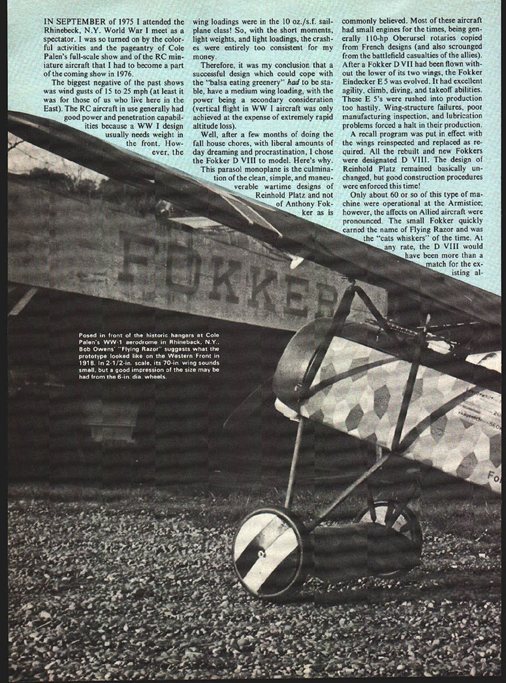
Only about 60 or so of this type of machine were operational at the Armistice; however, the effects on Allied aircraft were pronounced. The small Fokker quickly earned the name of "Flying Razor" and was the "cat's whiskers" of the time. At any rate, the D.VIII would have been more than a match for the existing allied aircraft.
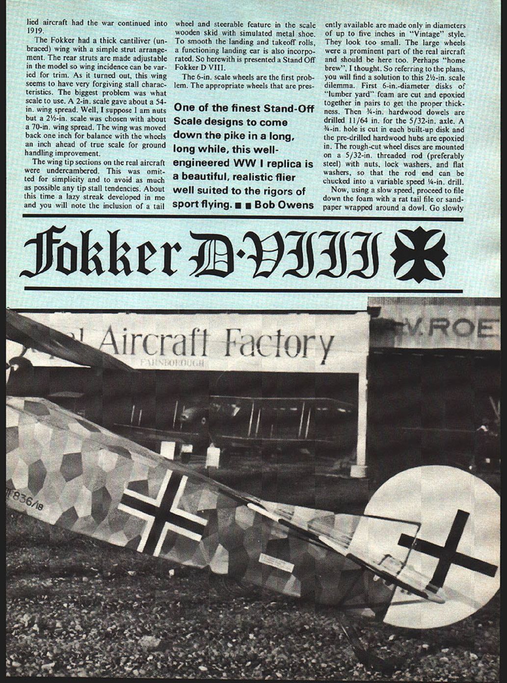
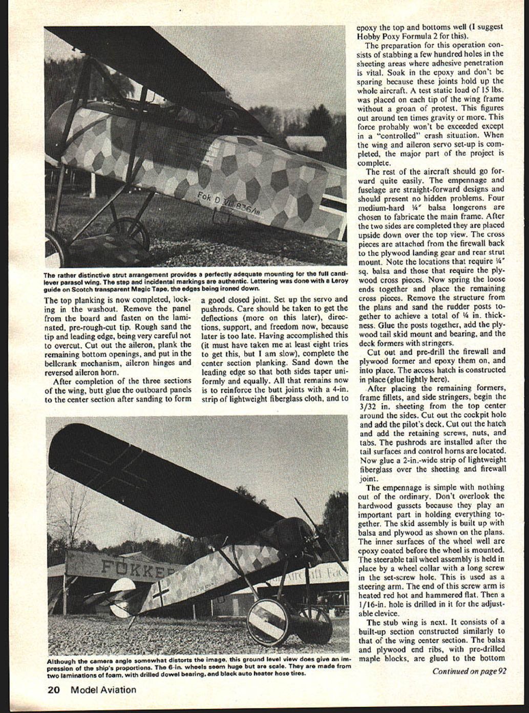
The Fokker's thick cantilever unbraced wing and simple strut arrangement were characteristic. On the model the rear struts were made adjustable so the wing incidence can be varied for trim. As turned out, the wing seems to have very forgiving stall characteristics. The biggest problem was what scale to use. A 2-1/2-in. scale gave about a 54-in. wing spread. Well, suppose I'm nuts — a 2-3/4-in. scale chosen about a 70-in. wing spread. The wing was moved back 1/2 in. for balance and the wheels 1/4 in. ahead for true scale ground handling improvement. The wing tip sections of the real aircraft were undercambered and were omitted for simplicity to avoid as much tip-stall tendency as possible.
About the time the lazy streak developed, I will note the inclusion of a tail wheel (a steerable feature), a scale wooden skid simulated metal shoe, smooth landing and takeoff rolls, and functioning landing gear also incorporated. So herewith presented: Stand-Off Fokker D.VIII.
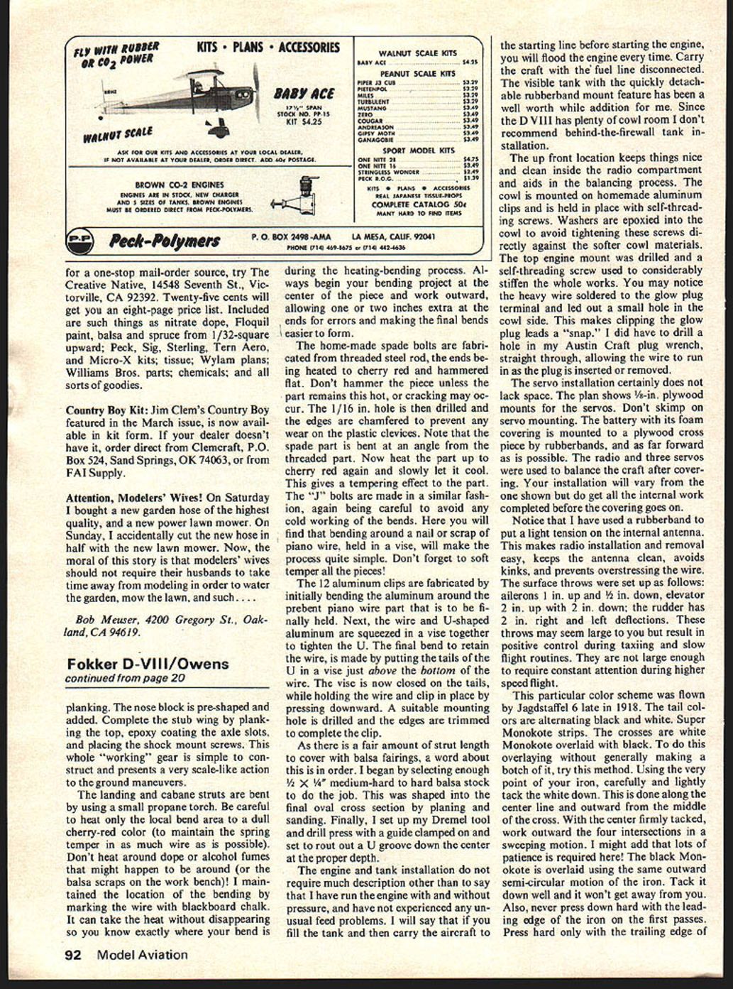
6-in. scale wheels — first problem: appropriate wheels. The finest Stand-Off Scale designs come down the pike — long, long well-engineered WWI replicas, beautiful realistic fliers well suited to the rigors of sport flying — but Bob Owens recently made diameters up to five inches. Vintage-style wheels look too small; large wheels are a prominent part of the real aircraft and should be on the model, too. Perhaps a home-brew thought. So, referring to the plans you will find the solution to the 2-1/2-in. scale dilemma.
First: 6-in.-diameter disks. From lumber-yard foam, cut and epoxied together in pairs to get the proper thickness. 3/8-in. hardwood dowels drilled 11/64 for a 5/32-in. axle. A 3/4-in. hole cut in the built-up disk for pre-drilled hardwood hubs epoxied in place. Rough-cut wheel discs mounted on a 5/32-in. threaded rod, preferably steel, with nuts, lock washers and flat washers. The rod end can be chucked in a variable-speed 1/4-in. drill. Now, using slow speed, proceed to file down the foam with a rat-tail file and sandpaper wrapped around the dowel. Go slowly. Use some solid tool rest to make sure the drill will move. Keep checking; soon you will have a rim-shaped taper and the hub rim produced by turning down the foam with a coarse file and sanding block.
After turning down the other wheel, file small 1/8-in. flat spots as shown on the plan to allow the bump between heater-hose ends to form the tires. Bare foam should be covered with heavy fiberglass and epoxy. Cover the rim first. Trim the side fiberglass that goes past the edge of the rim — trim rather than leave a sharp edge. Cover the fiberglass generously with epoxy; don't completely cover the cloth effect because it looks very realistic when painted. Be sure a good bond is formed between the wooden hub and the fiberglass side covering. Tires are cut 13/16-in. outside diameter from common black auto heater hose. You will need at least 20 inches of hose for a tire, I suggest. You will note the inclusion of a tail wheel and steerable feature in the scale wooden skid with simulated metal shoe. To smooth the landing and takeoff rolls, a functioning landing gear is also incorporated. So herewith is presented a Stand Off Fokker D VIII.
One of the finest Stand-Off Scale designs to come down the pike in a long, long while, this well-engineered WW I replica is a beautiful, realistic flier well suited to the rigors of sport flying. — Bob Owens
Fokker D-VIII
Use some solid tool rest and make sure the drill will not move. Keep checking and soon you will have the rim shaped. The taper from the hub to the rim is produced by turning down the foam with a coarse file and sanding block. After turning down the other wheel you should file small 1/8-in. flat spots as shown on the plan. These are to allow for the bump between the heater hose ends that form the tires. The bare foam should be covered with heavy fiberglass and epoxy. Cover the rim first, then trim it so the side fiberglass goes past the edge of the rim and then this, too, is trimmed to a rather sharp edge. Cover the fiberglass generously with epoxy but don't completely cover the cloth effect, because this looks very realistic when painted. Be especially sure that a good bond is formed between the wooden hub and the fiberglass side covering.
The tires are cut from 13/16-in. outside diameter common black auto heater hose. You will need at least 20 inches for each tire so I suggest a 6-ft. length. This will allow for one experimental fitting. Feed some soft iron wire through the hose twice, bring the ends out, and pull them together. Twist the loose wire ends with long-nose pliers after being satisfied with the fit on the rim. You will see that the flat spot on the rim is now filled with the tire splice. Finish up the joint with fine sandpaper and waterproof it with G. E. Silicon Seal or black bathtub caulking. As a finishing touch, try sanding the hose or using fine steel wool on it. You now have a pair of light-weight wheels that have survived a 5-ft. flat stall "landing."
The cowl is constructed using the turning methods used on the wheels. Use 1/4-in. threaded rod here with large flat washers (if none are available use 1/8-in. plywood disks) and very slow turning speeds. Make the foam plug about 1/16-in. smaller in radius than the firewall, 1/4-in. deeper than plan depth, and completely circular. Coat the completed plug with epoxy and then coat with a liberal amount of silicone spray or soft wax. Glue the plug to a scrap hardwood block and clamp it so it stays put. At this point I used the materials from an auto body patch kit rather than fiberglass cloth and epoxy.
The fiberglass mat was rough cut to size, then saturated in the two-part auto mix and laid over the plug. Keep the resin mix away from bare foam as it practically vaporizes it. Experiment with the amount of hardener you want. Make plenty of mix in advance, and work fast with disposable gloves or plastic "baggies" over your hands. Within ten minutes the cowl was completely laid up without wrinkles or matt overlaps. After allowing a thorough set, pull or cut the plug out of the glass shell. Now you can pick the best part for the top of the cowl, cut the front holes, and remove the bottom. Trim the extra 1/4-in. depth and complete the shell using medium sandpaper and woodfiller. It's really a great method with the results smooth, strong, tough, and to scale.
The wing is designed to be built in three sections without using any through gussets or spars. Heresy you cry? Too weak! Too chancy! Not so. At any rate, this three-section approach lends itself to building in a small space on a small 30-in. board. As you have noted, the wing used is the built-up type. A foam core with, say, 3/32 in. hard balsa planking could be used, providing the plywood cabane ribs are sandwiched in. However, the balsa wing was built, and here are the highlights and kinks of its construction.
Build the center section first after having cut out all the ribs, including the plywood ones. Next, pin and glue the flat bottom planking and bottom spars to the plan. Mark the rib locations and glue them to the pinned sheeting. Fasten pre-drilled maple wing blocks to the insides of the P.W. ribs and place these also. The blocked up leading edge now is glued in place. Put in the top spars, let it all dry, and remove the assembly from the board.
Complete the planking on the bottom. Plank the top temporarily, omitting three inches to facilitate servo and pushrod installation. Rough sand the leading edge, using a plywood or metal template as a guide. Locate the back spars through the covering and trace the wing cut-out on the bottom and top planking. Carefully cut this out and bevel-fit the inside pieces around the opening. Leave the servo mounts until later.
The wing outboard panels now are assembled by placing a piece of diagonally pre-cut and fitted planking down the trailing edge with another piece of planking "halved" under the front spar. This is to form a good splice where it is needed most. The bottom spars are located and glued down with the balsa ribs. Make a cardboard pattern of the dihedral angle and align the ribs with it. The leading edge stock can be purchased wide enough to allow cutting both outboard leading edges by making a diagonal cut with 1/8 in. saw allowance. This leading edge is now glued to the ribs.
With the leading edge held or pinned down, unpin the rest of the assembly so that a 1/4-in. block can be inserted under the tip rib to form the necessary washout.
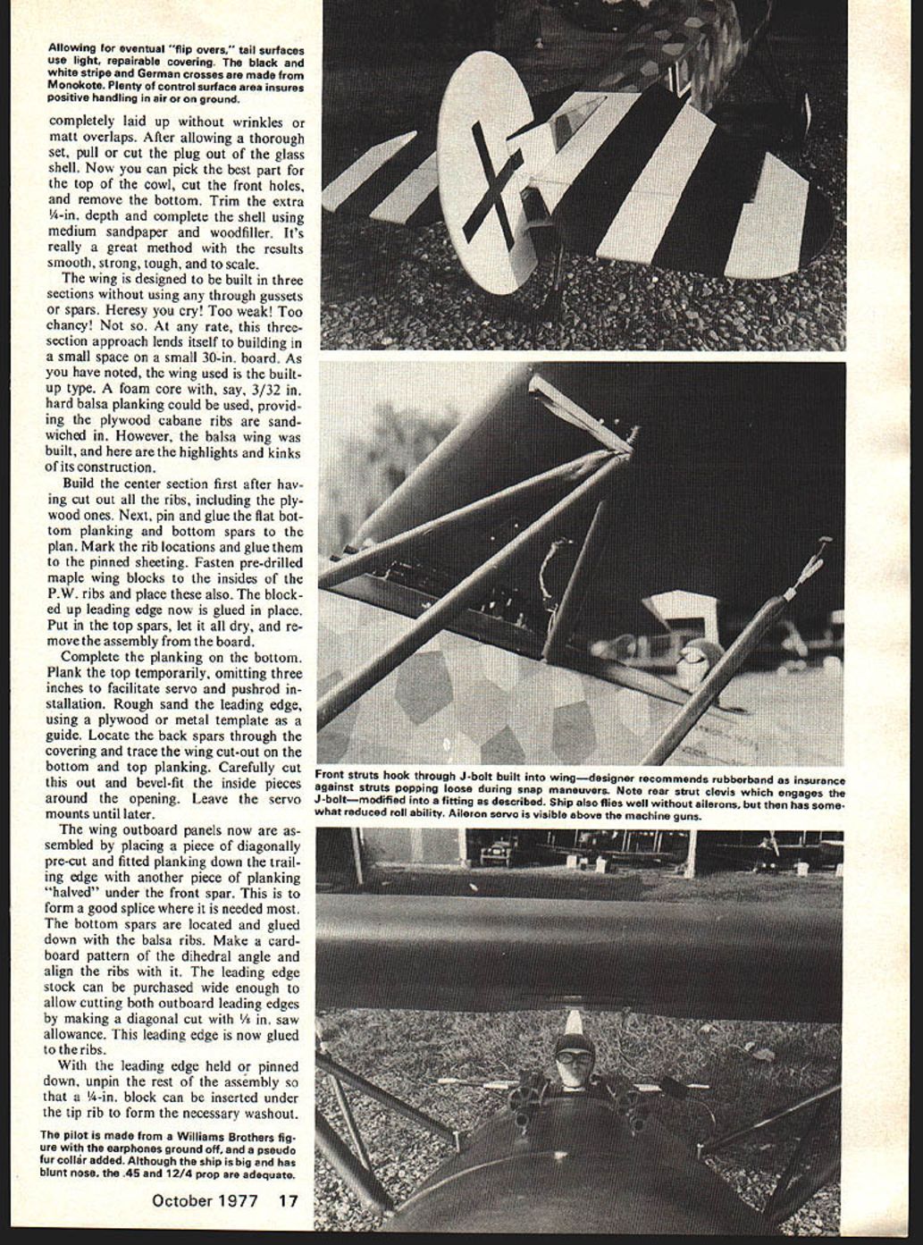
The pilot is made from a Williams Brothers figure with the earphones ground off, and a pseudo fur collar added. Although the ship is big and has blunt nose, the .45 and 12/4 prop are adequate.
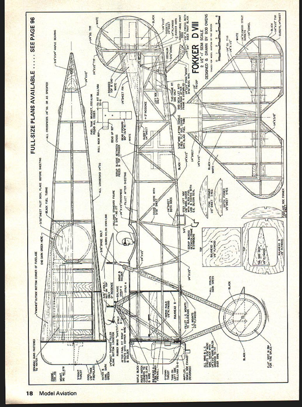
FOKKER D‑VIII
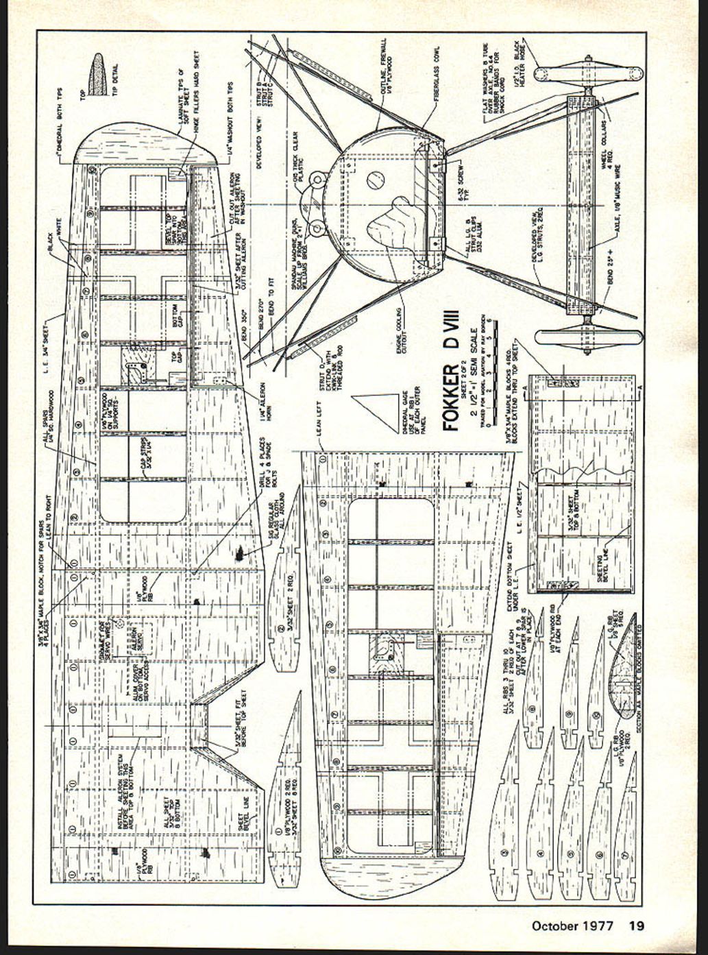
FOKKER D VIII 2-1/2" = 1' SCALE DESIGNED & DRAWN BY BOB OWENS
FOKKER D VIII
FOKKER D VIII 2-1/2" = 1' SCALE DESIGNED & DRAWN BY BOB OWENS The top planking is now completed, locking in the washout. Remove the panel from the board and fasten on the laminated, pre-rough-cut tip. Rough sand the tip and leading edge, being very careful not to overcut. Cut out the aileron, plank the remaining bottom openings, and put in the bellcrank mechanism, aileron hinges and reversed aileron horn.
After completion of the three sections of the wing, butt glue the outboard panels to the center section after sanding to form a good closed joint. Set up the servo and pushrods. Care should be taken to get the deflections (more on this later), directions, support, and freedom now, because later is too late. Having accomplished this (it must have taken me at least eight tries to get this, but I am slow), complete the center section planking. Sand down the leading edge so that both sides taper uniformly and equally. All that remains now is to reinforce the butt joints with a 4-in. strip of lightweight fiberglass cloth, and to epoxy the top and bottoms well (I suggest Hobby Poxy Formula 2 for this).
The preparation for this operation consists of stabbing a few hundred holes in the sheeting areas where adhesive penetration is vital. Soak in the epoxy and don't be sparing because these joints hold up the whole aircraft. A test static load of 15 lbs. was placed on each tip of the wing frame without a groan of protest. This figures out around ten times gravity or more. This force probably won't be exceeded except in a "controlled" crash situation. When the wing and aileron servo set-up is completed, the major part of the project is complete.
The rest of the aircraft should go forward quite easily. The empennage and fuselage are straight-forward designs and should present no hidden problems. Four medium-hard 1/4" balsa longerons are chosen to fabricate the main frame. After the two sides are completed they are placed upside down over the top view. The cross pieces are attached from the firewall back to the plywood landing gear and rear strut mount. Note the locations that require 1/4" sq. balsa and those that require the plywood cross pieces. Now spring the loose ends together and place the remaining cross pieces. Remove the structure from the plans and sand the rudder posts together to achieve a total of 1/4 in. thickness. Glue the posts together, add the plywood tail skid mount and bearing, and the deck formers with stringers.
Cut out and pre-drill the firewall and plywood former and epoxy them on, and into place. The access hatch is constructed in place (glue lightly here).
After placing the remaining formers, frame fillets, and side stringers, begin the 3/32 in. sheeting from the top center around the sides. Cut out the cockpit hole and add the pilot's deck. Cut out the hatch and add the retaining screws, nuts, and tabs. The pushrods are installed after the tail surfaces and control horns are located. Now glue a 2-in.-wide strip of lightweight fiberglass over the sheeting and firewall joint.
The empennage is simple with nothing out of the ordinary. Don't overlook the hardwood gussets because they play an important part in holding everything together. The skid assembly is built up with balsa and plywood as shown on the plans. The inner surfaces of the wheel well are epoxy coated before the wheel is mounted. The steerable tail wheel assembly is held in place by a wheel collar with a long screw in the set-screw hole. This is used as a steering arm. The end of this screw arm is heated red hot and hammered flat. Then a 1/16-in. hole is drilled in it for the adjustable clevice.
The stub wing is next. It consists of a built-up section constructed similarly to that of the wing center section. The balsa and plywood end ribs, with pre-drilled maple blocks, are glued to the bottom
Fokker D-VIII/Owens
planking. The nose block is pre-shaped and added. Complete the stub wing by planking the top, epoxy coating the axle slots, and placing the shock mount screws. This whole "working" gear is simple to construct and presents a very scale-like action to the ground maneuvers.
The landing and cabane struts are bent by using a small propane torch. Be careful to heat only the local bend area to a dull cherry-red color (to maintain the spring temper as much wire as possible). Don't heat around dope or alcohol fumes that might happen to be around (or the balsa scraps on the work bench)! I maintained the location of the bending by marking the wire with blackboard chalk. It can take the heat without disappearing so you know exactly where your bend is during the heating-bending process. Always begin your bending project at the center of the piece and work outward, allowing one or two inches extra at the ends for errors and making the final bends easier to form.
The home-made spade bolts are fabricated from threaded steel rod, the ends being heated to cherry red and hammered flat. Don't hammer the pieces unless the part remains this hot, or cracking may occur. The 1/16-in. hole is then drilled and the edges are chamfered to prevent any wear on the plastic clevises. Note that the spade part is bent at an angle from the threaded part. Now heat the part up to cherry red again and slowly let it cool. This gives a tempering effect to the part. The "J" bolts are made in a similar fashion, again being careful to avoid any cold working of the bends. Here you will find that bending around a nail or scrap of piano wire, held in a vise, will make the process quite simple. Don't forget to soft-temper all the pieces!
The 12 aluminum clips are fabricated by initially bending the aluminum around the pre-bent piano wire part that is to be finally held. Next, the wire and U-shaped aluminum are squeezed in a vise together to tighten the U. The final bend to retain the wire is made by putting the tails of the U in a vise just above the bottom of the wire. The vise is now closed on the tails, while holding the wire and clip in place by pressing downward. A suitable mounting hole is drilled and the edges are trimmed to complete the clip.
As there is a fair amount of strut length to cover with balsa fairings, a word about this is in order. I began by selecting enough 1/2 x 1/4 medium-hard to hard balsa stock to do the job. This was shaped into the final oval cross section by planing and sanding. Finally, I set up my Dremel tool and drill press with a guide clamped on and set to rout out a U groove down the center at the proper depth.
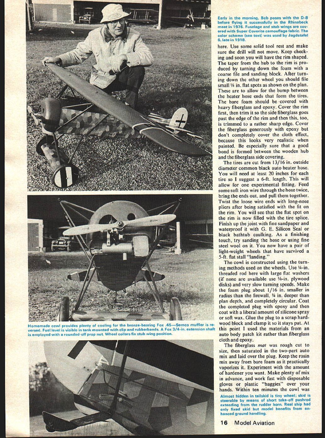
The engine and tank installation do not require much description other than to say that I have run the engine with and without pressure, and have not experienced any unusual feed problems. I will say that if you fill the tank and then carry the aircraft to the starting line before starting the engine, you will flood the engine every time. Carry the craft with the fuel line disconnected. The visible tank with the quickly detachable rubberband mount feature has been a well worth while addition for me. Since the D VIII has plenty of cowl room I don't recommend behind-the-firewall tank installation.
The up front location keeps things nice and clean inside the radio compartment and aids in the balancing process. The cowl is mounted on homemade aluminum clips and is held in place with self-threading screws. Washers are epoxied into the cowl to avoid tightening these screws directly against the softer cowl materials. The top engine mount was drilled and a self-threading screw was used to considerably stiffen the whole works. You may notice the heavy wire soldered to the glow plug terminal and led out a small hole in the cowl side. This makes clipping the glow plug leads a "snap." I did have to drill a hole in my Austin Craft plug wrench, straight through, allowing the wire to run in as the plug is inserted or removed.
The servo installation certainly does not lack space. The plan shows 1/8-in. plywood mounts for the servos. Don't skimp on servo mounting. The battery with its foam covering is mounted to a plywood cross piece by rubberbands, and as far forward as is possible. The radio and three servos were used to balance the craft after covering. Your installation will vary from the one shown but do get all the internal work completed before the covering goes on.
Notice that I have used a rubberband to put a light tension on the internal antenna. This makes radio installation and removal easy, keeps the antenna clean, avoids kinks, and prevents overstraining the wire. The surface throws were set up as follows: aileron 1 in. up and 1/2 in. down; elevator 2 in. up with 2 in. down; the rudder has 1 1/2 in. right and left deflections. These throws may seem large to you but result in positive control during taxiing and slow flight routines. They are not large enough to require constant attention during higher speed flight.
This particular color scheme was flown by Jagdstaffel 6 late in 1918. The tail colors are alternating black and white. Super Monokote strips. The crosses are white Monokote overlaid with black. To do this overlaying without generally making a botch of it, try this method. Using the very point of your iron, carefully and lightly tack the white down. This is done along the center line and outward from the middle of the cross. With the center firmly tacked, work outward the four intersections in a sweeping motion. I might add that lots of patience is required here! The black Monokote is overlaid using the same outward semi-circular motion of the iron. Tack it down well and it won't get away from you. Also, never press down hard with the leading edge of the iron on the first passes. Press hard only with the trailing edge of the iron.
The fuselage is covered with 2-in. scale camouflage Super Coverite fabric. This iron-on material was applied without any fuss. First the bottom, then the sides, and finally the top areas are covered. It soon becomes apparent that a very uniform overlap width has to be achieved, since the camouflage patterns do not generally match around the fuselage corners. To do this, use a short 3/4-in. plywood guide. Cut against this with a freshly sharpened X-Acto knife and a good edge lap will result.
The wing is covered with Super Coverite, the bottom first, then the top. At the tips you really can pull the covering around without gores since these tips are truly solid. Most of the stub wing is done in the 2-in. camouflage with the sides painted last. The dark green paint for the wing, cowl, and struts is Superpoxy brush-type paint that is slightly thinned and mixed one part black to two parts green. A small Badger-Propel spray gun was used for the required two coats. This produces a weathered dull finish.
The wheels are painted with black and white Superpoxy. The cowl, struts, and wheel backs are painted with the dark green mix. Finally, after all the covering and spraying operations are completed you should rub down all the shiny surfaces with very fine steel wool. This achieves a more uniform dull finish.
My aircraft was finally completed, test run and taxied around the back yard using three tanks of fuel. This was done to make sure that nothing was about to loosen, fail, or fall off! It also checked the fuel consumption of the Fox bushed bearing 0.45 engine.
Later, at the club field, as I fought cold feet, my wife, the mechanic said, "You built a scale model; the original flew didn't it? Well when are you going to try?" The challenge had been called! Our club has a 200-ft. grass strip field. The taxi to the far edge was completed and the wind O.K. A final control check, an engine run up, and the throttle back to 3/4. Let go. She rolls. So back to 1/2 throttle, all with full up elevator. With some good speed now, a neutral elevator, some left rudder and I firewallled the throttle. The lift off was less than half field! This had to be the greatest thrill in modeling since my solo.
I gained some altitude and warmed up to the flying. She flew hands off at all throttle settings without major trim changes. Large, perfect aileron-only turns were made, but in the tight maneuvers the rudder was the only way to go. (In fact, flying three-channel without ailerons would be quite natural, and would simplify the wing construction. However, the rolling ability would suffer if this is done.) According to the timer I had about five minutes more fuel. Some stalls, stall turns, and slow flight were tried with good smoothness of control. The landing, from my wife's point of view, was a steep approach, nice flare-out into a fast roll-out.
After over three months of no flying this had to be the aircraft, because I was flying with two fists inside mittens. The D VIII almost landed by itself. I put her through three hours of air time before the Rhinebeck meet. I think it only fair to do this as far as public safety is concerned. At the meet I looked at the balsa consuming trees bending in the wind and said "here goes my first design effort, first major contest, and first time flying away from the big club field."
As a "realistic" speed made points with the judges I flew the first flight slowly. Actually too slowly! Fifty feet over trees with minimum air speed and on the downward leg is not the best place to have the engine quit! That D VIII tucked her nose into a nice glide, made a one-eighty on descent and flared deadstick into the 50-ft. spot circle. And that is the truth. After that the D VIII and I had a time that will long be pleasantly remembered. Many modelers saw the aircraft first hand and performing in the air. Amazement was expressed that a big blunt-front, thick-winged aircraft could be so stable and fly with only a 0.45 engine (using a 12 x 4 Tornado prop).
If you decide to build the Fokker, don't expect a pattern aircraft that will do clean aileron rolls and fly all day inverted. It won't. Expect a smooth, stable aircraft with a reasonable amount of penetration capability, good ground handling, and just realistic flight.
I would like to express my gratitude to all the people who made this project possible: to my wife Ginny, for encouragement, to Mr. Otto Lorenz, who made these fine photographs, and to Mr. Cole Palen and the members of the Mid-Hudson R.C. Society who gave their permission and dedication to inspire this project.
Transcribed from original scans by AI. Minor OCR errors may remain.

