
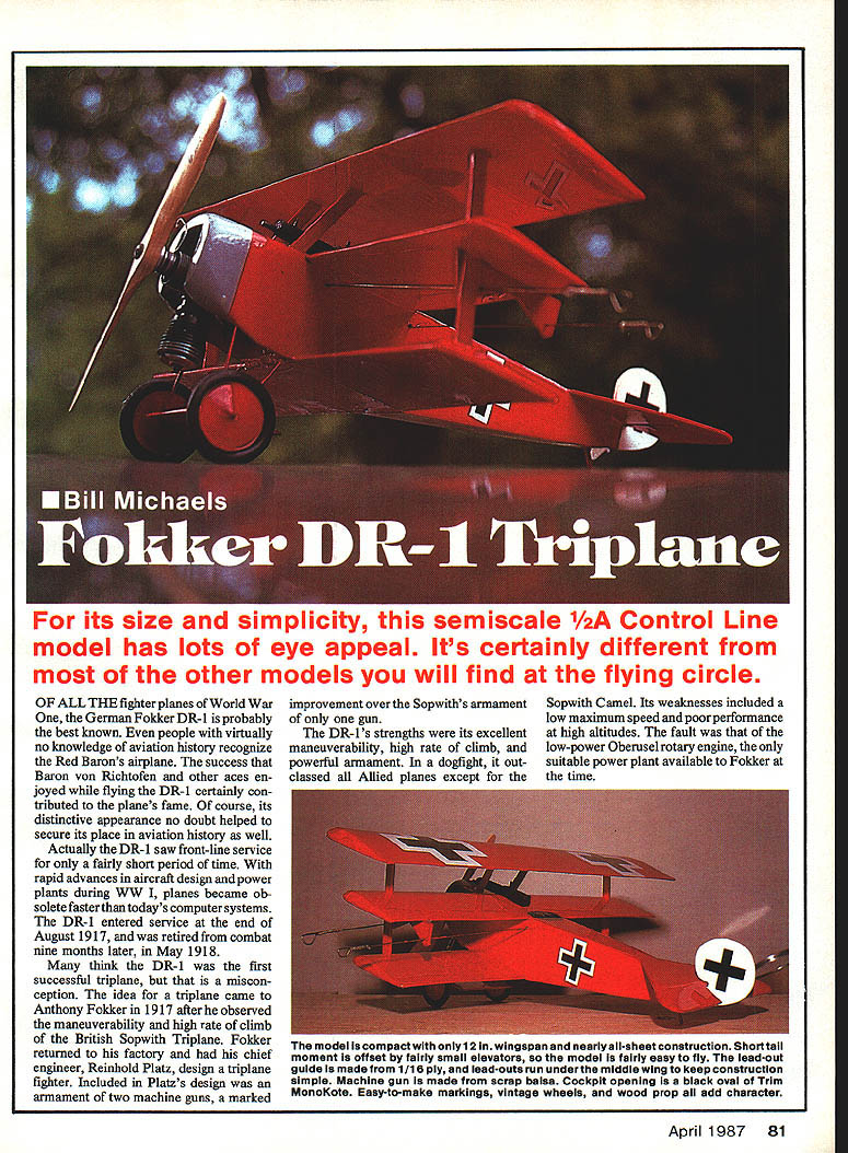
Fokker DR-1 Triplane
Bill Michaels
For its size and simplicity, this semi-sport, stand‑away scale 1/2A control-line model has lots of eye appeal. It's certainly different from most of the other models you will find at the flying circle.
History
Of all the fighter planes of World War One, the German Fokker DR‑1 is probably the best known. Even people with virtually no knowledge of aviation history recognize the Red Baron's airplane. The success that Baron von Richthofen and other aces enjoyed while flying the DR‑1 certainly contributed to the plane's fame. Its distinctive appearance also helped secure its place in aviation history.
The DR‑1 saw front-line service for only a fairly short period. With rapid advances in aircraft design and power plants during WWI, planes became obsolete quickly. The DR‑1 entered service at the end of August 1917 and was retired from combat nine months later, in May 1918.
Many think the DR‑1 was the first successful triplane, but that is a misconception. The idea for a triplane came to Anthony Fokker in 1917 after he observed the maneuverability and high rate of climb of the British Sopwith Triplane. Fokker had his chief engineer, Reinhold Platz, design a triplane fighter that included an improvement over the Sopwith's single-gun armament.
The DR‑1's strengths were excellent maneuverability, a high rate of climb, and powerful armament. In a dogfight it outclassed most Allied planes except the Sopwith Camel. Its weaknesses included a low maximum speed and poor performance at high altitudes, mainly due to the low-power Oberursel rotary engine, the only suitable power plant available to Fokker at the time.
Model overview
- Scale: semi-sport, stand‑away scale
- Power: 1/2A engine (engine modification described below)
- Covering: MonoKote (bright red recommended)
- Wheels: 1-1/2 in. diameter with rubber O‑ring tires
- Construction style: foam-core wings with balsa skins; 1/16-in. sheet balsa tail surfaces; balsa fuselage planked top and bottom
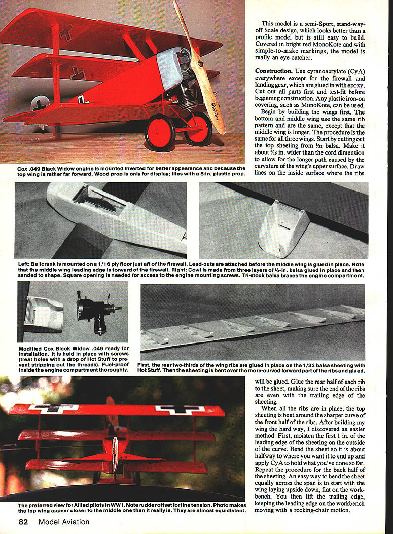
This model is eye-catching when covered in bright red MonoKote with simple markings. It is easy to build and fly while looking better than a profile model.
Construction
Use cyanoacrylate (CyA) for most assemblies, except for firewall and landing gear joints—use epoxy for those. Cut out all parts and test-fit before beginning. Any plastic iron-on covering, such as MonoKote, can be used.
Materials and adhesives
- Cyanoacrylate (CyA) for most joints
- 45‑minute epoxy for skinning and structural joints
- Hot Stuff (thin CA) for sheeting/rib attachment
- 1/16-, 1/32- and 1/8-in. balsa as specified
- Foam cores for wings
- 1/16-in. brass tubing for lead-out bushings
- 1/16- and 1/8-in. music wire as required
- 1/8-in. fiberglass strips (1/8-in. wide) for butt joint reinforcement
- Playing card or spreader for epoxy removal
- Lightweight contest 1/16-in. balsa for skins (edge-glued to width)
Wings — general
The bottom and middle wings use the same rib pattern; the middle wing is longer. The same procedure applies to all three wings.
- Cut top sheeting from 1/32-in. balsa. Make it about 3/16 in. wider than the chord to allow for the curvature of the upper surface. Draw lines on the inside surface to locate the ribs.
- Glue the rear two-thirds of the wing ribs to the 1/32-in. sheeting using Hot Stuff (thin CA). Then bend the sheeting around the more-curved forward part of the ribs and glue. Ensure rib ends are even with the trailing edge of the sheeting.
- For easier bending: moisten the first 1 in. of the leading-edge sheeting on the outside curve, bend the sheet halfway to the final shape and apply a small amount of CyA to hold. Repeat for the back half. A practical technique is to start with the wing upside down on the bench, then turn it up by lifting the trailing edge while keeping the leading edge on the bench, using a rocking motion.
- Attach wing tips by adding a tip rib and sanding to match the airfoil.
- Cut holes in the sheeting of the middle and bottom wings for the wing struts. Sand 3/32 in. off the bottom of the two center ribs and attach the bottom sheeting so it is flush with the bottom of the wing.
- Glue leading- and trailing-edge strips with a thin spread of epoxy and hold in place with tape while the epoxy sets.
- Sand leading and trailing edges to shape. To avoid sanding the foam core, tape a piece of lightweight cardboard (notebook divider) over the foam butted against the balsa, then block-sand the balsa. Replace the cardboard as needed. When the balsa is smooth and even with the cardboard, remove the cardboard and carefully sand until the balsa is smooth with the foam.
Notes:
- If the balsa skin overlaps the leading edge, sand the leading-edge balsa similarly, or glue and sand the leading edge after the skin is on.
- Lightly block-sand the foam core to remove ridges only; do not over-sand the thin foam. Vacuum the sanded foam carefully.
Wing skinning
- Edge-glue enough 1/16-in. contest balsa sheets together to cover one side of the wing.
- Mix enough 45‑minute epoxy to cover two skins. Apply epoxy to the balsa skin and use a playing card to spread and remove excess. The skin should be only damp with epoxy; avoid excess which only adds weight.
- Lightly coat trailing-edge, leading-edge overlap, and plywood spar edge—do not over-apply epoxy.
- Apply skins with the cavity cores in place for rigidity. Starting at the leading edge, roll the skin over the core. Do the same on the other side.
- Place the subassembly back into the outer core saddles and add weights to compress everything while the epoxy cures.
Bellcrank assembly and lead-outs
- Make the bellcrank assembly with the lead-outs. Bush the lead-outs with 1/16‑in. brass tubing through the bellcrank.
- Slip the lead-out through a 1-1/2 in. length of tubing; slide this tubing through the bellcrank and bend the tubing in a smooth radius.
- Make lead-out cable connections per AMA rule book.
- Assemble the bellcrank so the pushrod connection does not interfere with movement. Notch the inboard wing for the bellcrank support and pushrod exit. The pushrod should be installed without bends between the flap horn and bellcrank—this may require a larger exit notch.
- Epoxy the bellcrank assembly in the inboard wing. Verify smooth operation before proceeding.
Wing assembly and join
- With both wing halves supported in the outer core saddles for alignment, trim excess balsa skin at both inboard edges. Do not sand the foam cores — keep them square. Remove the cavity cores.
- Lightly coat the foam cores and balsa skin in the inboard areas with 45‑minute epoxy.
- Mate the two wing halves together in the core saddles, ensuring trailing edges are straight and aligned. Allow epoxy to set.
- Cut two 5 x 1 in. plywood bellcrank supports, drill through their centers, and epoxy them to the wing skin to give the bellcrank area enough strength for 40‑ to 50‑lb pull tests.
- Reinforce the wing butt joint with 1/8‑in. strips of fiberglass: lay down the fiberglass and brush epoxy through it. Remove excess epoxy with a playing card to keep weight down.
Weigh the completed wing. For competitive precision aerobatics the wing should not exceed about 8 oz. If too heavy, consider lighter balsa or materials; the most likely cause is using 1/16‑in. balsa that is heavier than contest grade.
A foam-core wing is generally easier, faster, and straighter than a built-up wing. The completed wing uses roughly $10 worth of materials and about 10 man-hours; template making is half the time, so subsequent wings can be made in about five hours.
Covering
Each wing is covered the same way using one piece of MonoKote:
- Attach the covering to the top of the trailing edge and wrap it around the rear, across the bottom, and attach it to the leading edge.
- Then attach the material to the top surface.
- If handy with MonoKote, cover the wing tips in one piece; otherwise cover tips first and then the rest of the wing.
- Glue three pennies into the right tip of the bottom wing for trim weight.
Tail surfaces
- Tail surfaces are made from 1/16‑in. sheet balsa and are easy to assemble.
- The rudder is built from three pieces of wood with grain directions as shown on the plans; this gives greater strength than one-piece construction.
- The elevators are joined with a piece of 1/16‑in. music wire and attached to the stab with a strip of MonoKote ironed across the top of the gap to serve as a hinge.
- Ensure the gap between elevator halves allows both downward and upward deflection.
Fuselage
- Drill small holes in the firewall where the engine mounting screws go.
- Prepare the 1/16‑in. balsa fuselage sides by gluing 3/16‑in. tri-stock along the rear edges of the fuselage. Build a left and a right side.
- Glue the 3/4‑in. tri bellcrank mount supports and rear firewall braces in place.
- Glue the firewall, bellcrank mount, and rear 1/8‑in. balsa bulkhead to the fuselage sides. Ensure everything is square to avoid a warped fuselage.
- When dry, add the 3/16‑in. tri braces to the front of the firewall.
- Bend the tail skid from 1/8‑in. music wire and epoxy it to the front side of the bulkhead.
- Plank the fuselage bottom aft of the wing with 1/16‑in. balsa with the grain running across the fuselage.
- Bend the pushrod to shape, install it and the bellcrank, glue the stab in position, and check for any binding or slop in the control system.
- If all is well, plank the top of the fuselage aft of the wing. The lead-outs are installed before the middle wing is glued on. Attach the two 1/16‑in. pieces that make up the rear of the fuselage under the stab.
Engine modification and installation:
- Modify the engine so the cylinder points backward by removing the four screws on the back of the fuel tank, rotating the tank 180°, and replacing the screws.
- Round the corners of the tank area, smoothing it into the fuselage, and cut away material as needed to make room for the engine and for a screwdriver to tighten the mounting screws.
- Cut holes in the fuselage top for the needle valve and fuel filler.
- Paint the inside of the engine compartment with fuel‑proof dope.
- Attach the lead‑outs to the bellcrank, and glue the bottom and middle wings in place, making certain they are parallel and that any covering is cut away to create a good wood‑to‑wood joint.
- Install the spruce wing struts and lead‑out guide. Cut holes in the bottom of the top wing for the struts and cabanes, glue the top wing to the struts ensuring it is parallel to the middle wing, then add the cabane struts.
Landing gear and wheels:
- Bend 1/16‑in. music wire to the shape shown on the plans. Put the wheels on the axle and bend the axle ends so the wheels won't fall off.
- Attach the axle to the landing gear by setting it in place and wrapping the joint with fine wire. Soldering can be used to reinforce but is not required.
- Glue the landing gear to the model. The rear crossbar is epoxied to the bottom of the firewall; the front legs are epoxied to 1/4‑in. triangular cowl supports inside the engine compartment.
- Attach the axle wing to the axle with epoxy; a dab of epoxy between the axle wing and the landing‑gear/axle joint will keep the axle wing from rotating.
Cowl:
- Make the cowl from three laminations of 1/32‑in. balsa glued over a form. Sand the cowl to shape, cut the engine opening, and finish/paint as desired.
Finishing
- Glue the rudder in place with a 1/4‑in. offset to the right.
- Make markings from black and white MonoKote (trim or regular).
- I added a single machine gun from scrap balsa, but left the cowl off to access the needle valve.
- Install the engine, adding one washer to offset it to the outside of the circle if required.
- Check the balance point and set the center of gravity as shown on the plans. If the model is nose heavy, add weight to the tail to bring the C.G. to the correct position.
Flying
- Use 30‑ to 35‑ft. lines.
- It is easier to start the engine with the plane inverted, then flip it over to fine‑tune the needle valve. Keep fingers away from the prop.
- Pass the starting-battery wires through the landing gear so they are less likely to get caught in the prop.
- Adjust the needle valve from behind the top wing, not in front of it.
- The DR‑1 will leap into the air after a short takeoff run. It flies well and is fairly maneuverable but is not a good glider—be ready when the engine quits.
Thanks to Bob Vogel, photographic hobbyist, for the pictures used with this article.
Transcribed from original scans by AI. Minor OCR errors may remain.

