
Fokker D.VIII
James E. Gilgenbach
Introduction
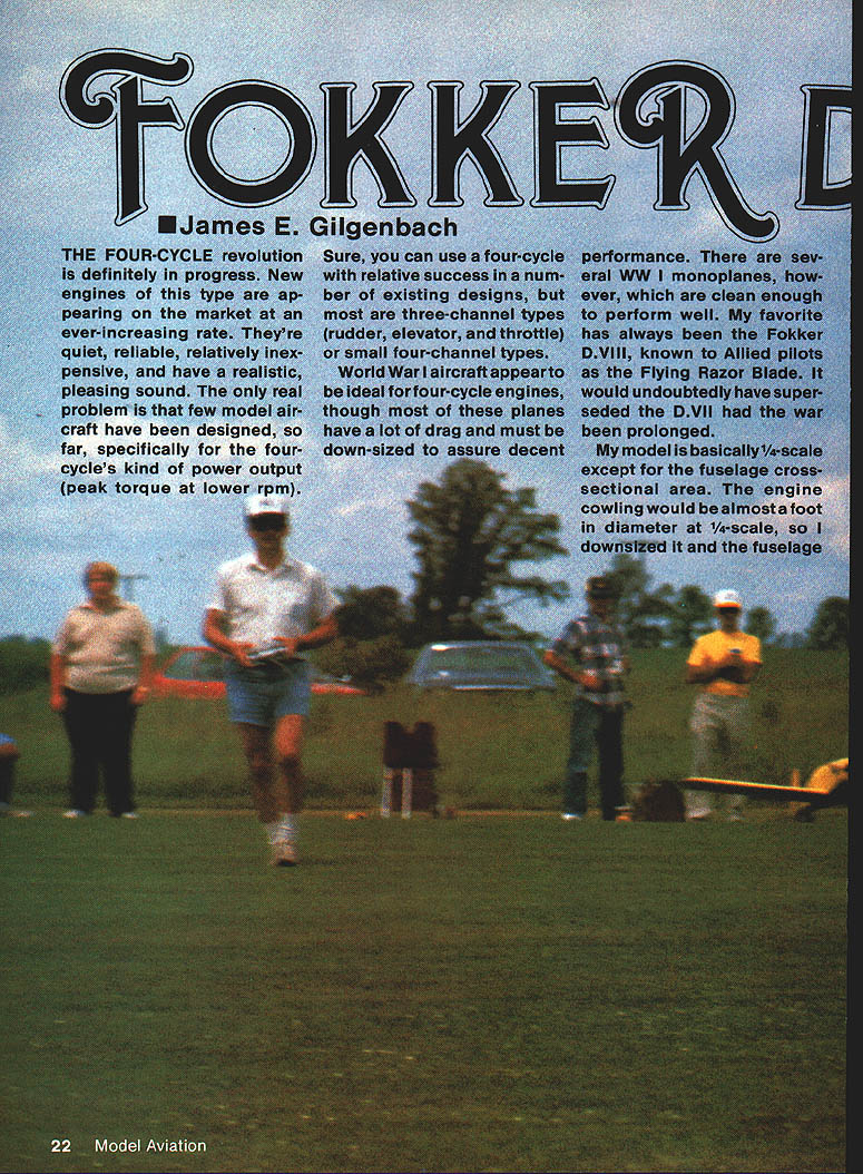
The four-cycle revolution is definitely in progress. New four-stroke engines are appearing on the market at an ever-increasing rate: they are quiet, reliable, relatively inexpensive, and have a realistic, pleasing sound. The only real problem is that few model airframes have been designed specifically for four-cycle power output (peak torque at lower RPM). You can use a four-cycle in many existing designs with relative success, but most of those are three-channel types (rudder, elevator, throttle) or small four-channel types.
World War I monoplanes are often ideal for four-cycle engines, though many full-scale WW I designs have heavy drag and must be down-sized for acceptable model performance. The Fokker D.VIII — known to Allied pilots as the "Flying Razor Blade" — is a clean WW I monoplane and my favorite. It would likely have superseded the D.VII had the war continued.
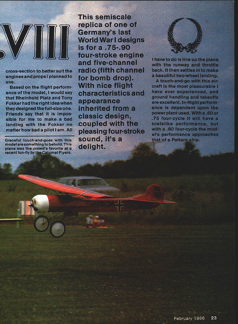
My model is roughly 1/4-scale except that the fuselage cross-section is reduced to better suit available engines and props. This semiscale replica is designed for a .75–.90 four-stroke engine and five-channel radio (fifth channel for bomb drop). It offers pleasant four-stroke sound, good appearance, and fine flight characteristics. With a .60 or .75 four-cycle it flies with scale-like performance; with a .90 four-cycle its performance approaches that of a Pattern ship.
Construction is straightforward and uses standard materials. I typically build the wing first, then the fuselage and tail surfaces, but components may be built in any order.
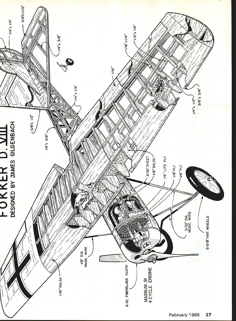
General design and features
- Wing: spruce spars, Lite Ply and balsa ribs, balsa sheeting; built-up structure with fiberglass pushrods and bellcranks.
- Landing gear: 5/32-in. music wire, wrapped with copper wire and silver-soldered; 1/4-20 nylon bolts for mounting.
- Wing mounting: Wing Mfg. metal inserts in hardwood hold-down blocks and Du-Bro 4-20 wing bolts.
- Fuselage: lite plywood doublers, spruce longerons, diagonal braces to keep the rear light (no nose weight required).
- Cowl: plywood, balsa and Styrofoam plug, fiberglassed, microballoon fairing coats.
- Extras: Vortac bomb-release, Sullivan cables to aileron horns, removable tail surfaces for transport.
Wing construction
Strength test and wing-mounting summary
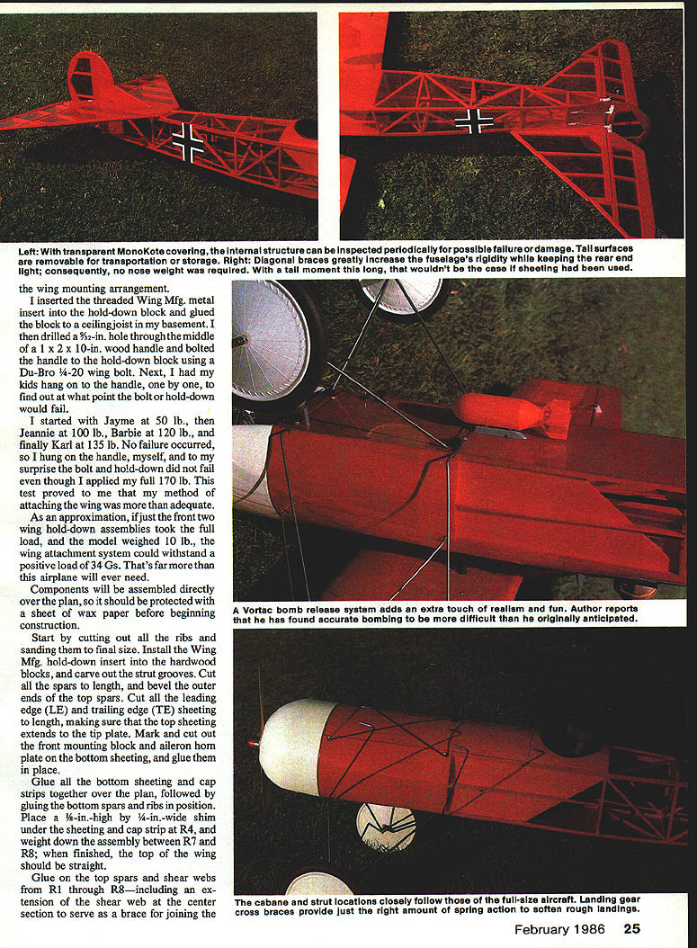
Prior to finalizing the wing-mounting arrangement I tested the hold-down method. I glued a threaded Wing Mfg. metal insert into a hardwood hold-down block, fixed the block to a joist, bolted a 1 x 2 x 10-in. wood handle to it with a Du-Bro 4-20 wing bolt, and applied load by having family members hang on the handle. No failure occurred up to 135 lb. At about 170 lb the bolt and hold-down finally failed, demonstrating that the attachment method is more than adequate for the model. As an approximation: if the front two hold-down assemblies took the full load and the model weighed 10 lb, the wing attachment could withstand a positive load of about 34 Gs — far beyond what the model will encounter.
The wing halves are assembled directly over the plan. Protect the plan with a sheet of wax paper before beginning.
Materials and initial steps
- Cut out ribs and sand to final size.
- Install Wing Mfg. hold-down inserts into hardwood blocks; carve strut grooves.
- Cut spars to length and bevel outer ends of the top spars.
- Cut leading-edge (LE) and trailing-edge (TE) sheeting to length; ensure top sheeting extends to the tip plate.
- Mark and cut the front mounting block and aileron horn plate in the bottom sheeting and glue them in place.
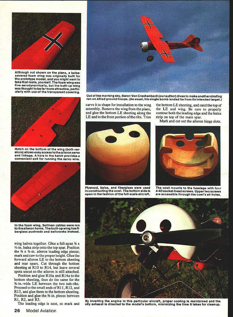
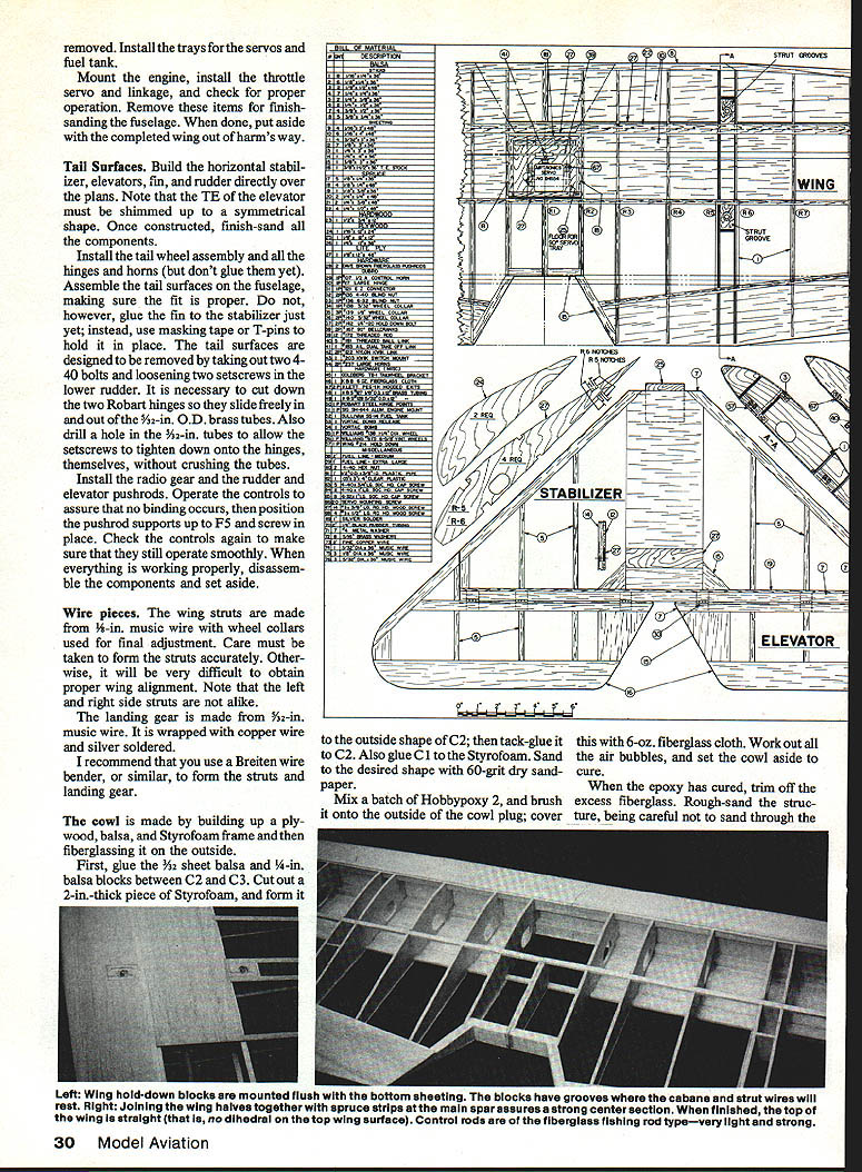
Glue the bottom sheeting cap strips together over the plan; then glue bottom spars and ribs in position. Place a 3/8-in.-high by 1/4-in.-wide shim under the sheeting cap strip at R4 and weight down the assembly between R7 and R8 so the top wing is straight when finished.
Glue the top spars and shear webs from R1 through R8, including the extension shear web at the center section that serves as the brace joining the panels.
Ailerons and LE work
- Glue a full-span 1/8-in. balsa strip onto the top spar.
- Position 1/8 x 3/4-in. aileron leading-edge pieces; mark and saw to proper height.
- Glue the forward aileron LE to the bottom sheeting and rear spars.
- Cut through the bottom sheeting at R10–R14, leaving several spots uncut so the aileron remains attached.
- Position and glue R10a–R14a on the bottom sheeting and glue the same 3/8-in.-wide LE between the two sub-ribs.
- Proceed to the small ends R11–R13 (or R1–R3 in root area), glue bottom sheeting and position glue-in pieces at the leading edge, then mark and carve the aileron shape.
- Mark and cut the aileron hinge slots.
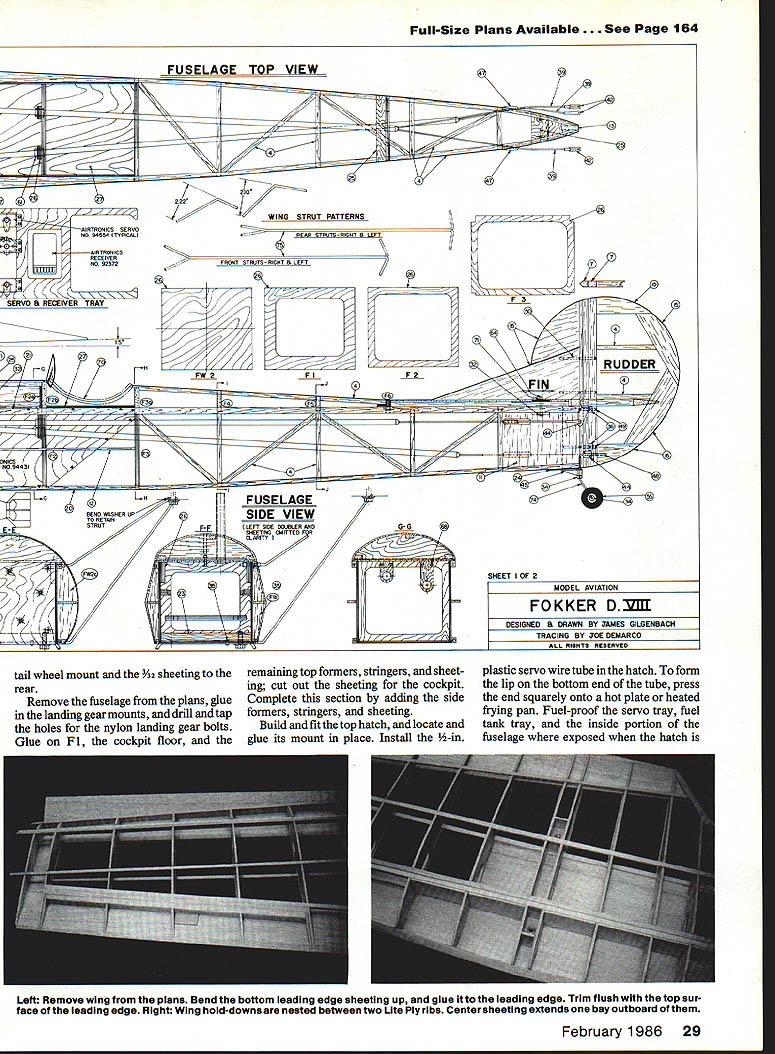
After these steps, remove the wing from the plans, glue the bottom LE sheeting along the LE and front portion of the ribs, trim and sand the LE for proper contour, glue the leading-edge balsa strip to the top main spar, and complete the hinge slot work.
Final wing assembly
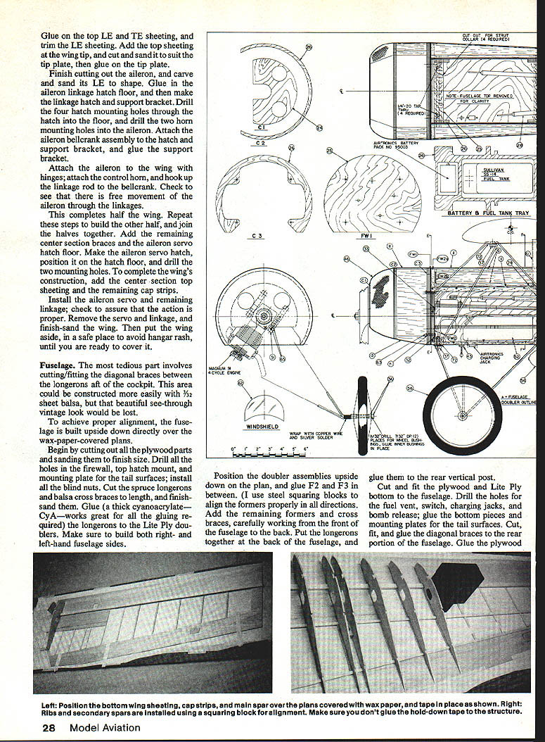
- Glue the top LE and TE sheeting; trim the LE sheeting.
- Add top sheeting at the wing tip and glue on the tip plate after fitting and sanding.
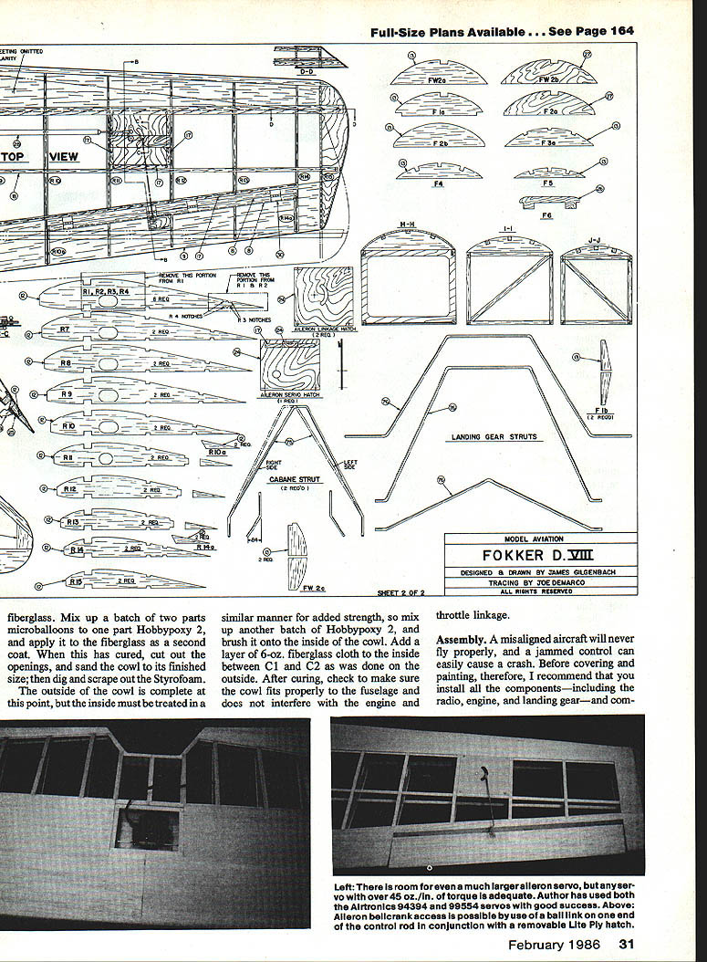
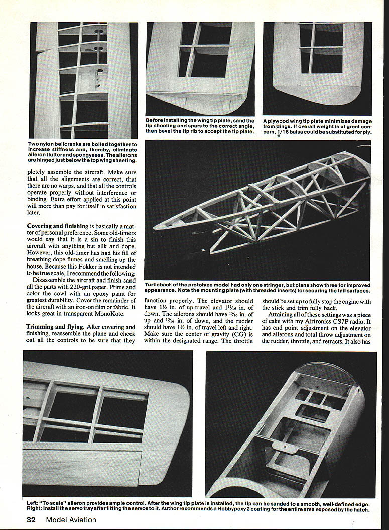
- Finish-cut the aileron, shape its LE, and build the aileron linkage hatch and support bracket.
- Drill hatch and horn mounting holes, attach the aileron bellcrank assembly to the hatch and bracket, and glue the support bracket.
- Install aileron hinges, control horn, and hook up linkage to the bellcrank. Check for free movement.
- Repeat the build for the other half, join halves together, add center-section braces and the aileron servo hatch floor, install the aileron servo and linkage, check action, remove servo and linkage, and finish-sand the wing.
- Cover the internal structure with transparent MonoKote to allow periodic inspection for possible damage.
Fuselage
Build the fuselage upside down over plans protected with wax paper to achieve proper alignment.
Steps
- Cut and sand all plywood parts to final size. Drill holes in firewall, top hatch mount, and tail-surface mounting plate; install blind nuts.
- Cut spruce longerons and balsa cross braces; finish-sand.
- Glue longerons to Lite Ply doubler blocks (thick cyanoacrylate works well). Build both right and left fuselage sides.
- Position doubler assemblies on the plan; glue formers F2 and F3 in place using steel squaring blocks to align formers. Add remaining formers and cross braces, working front to back.
- Join longerons at the rear and glue to the rear vertical post.
- Cut and fit the plywood and Lite Ply bottom, drilling holes for fuel vent, switch, charging jacks, and bomb release. Glue bottom pieces and tail mounting plates.
- Cut, fit and glue diagonal braces to the rear portion. Glue plywood tailwheel mount and 3/32-in. sheeting to the rear.
- Remove fuselage from plans, glue in landing gear mounts, drill and tap holes for nylon landing gear bolts.
- Glue on F1, cockpit floor, and remaining top formers, stringers, and sheeting; cut out cockpit openings.
- Build and fit the top hatch; install a 1/2-in. plastic servo wire tube in the hatch (form the bottom lip by pressing onto a hot plate). fuel-proof the servo tray, fuel-tank tray, and exposed inside fuselage areas around the hatch.
- Mount the engine, install throttle servo and linkage, check operation, then remove these items for finishing and sanding.
Diagonal braces greatly increase fuselage rigidity while keeping the rear light; consequently no nose weight is required. Cabane strut locations follow the prototype, and landing-gear cross braces provide good spring action for rough landings. Sullivan cables run to the aileron horns.
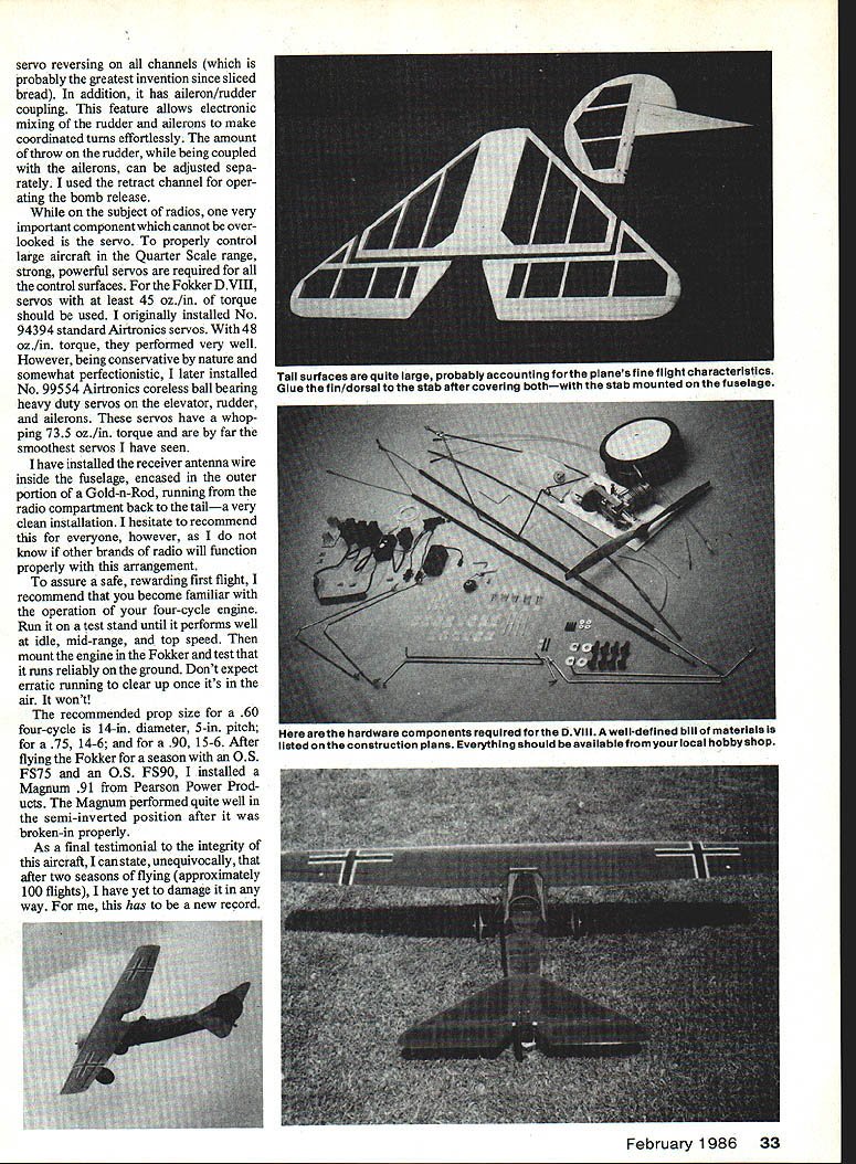
Tail surfaces
Build the horizontal stabilizer, elevators, fin, and rudder directly over the plans; shim the elevator TE to achieve a symmetrical shape and finish-sand all components.
- Install the tailwheel assembly, hinges and horns (do not glue them yet).
- Assemble tail surfaces on the fuselage to check fit. Do not glue the fin to the stabilizer; hold in place with masking tape or T-pins.
- Tail surfaces are removable by taking out two 4-40 bolts and loosening two setscrews in the lower rudder. Cut down two Robart hinges so they slide freely in/out of the 3/32-in. O.D. brass tubes. Drill a hole in the 5/32-in. tubes to allow setscrews to tighten onto the hinges without crushing the tubes.
- Install radio gear and rudder/elevator pushrods. Operate controls to check for binding, then position pushrod supports to F5 and screw in place. Recheck controls, then disassemble and set parts aside.
Wire pieces and landing gear
- Wing struts: 1/8-in. music wire with wheel collars used for final adjustment. Form accurately; left and right struts are not identical.
- Landing gear: 5/32-in. music wire, wrapped with copper wire and silver-soldered.
- Use a wire bender (Breiten or similar) to form struts and landing gear.
Cowl construction
The cowl is built on a plywood, balsa and Styrofoam plug and is fiberglassed outside and inside.
- Glue 3/32-in. sheet balsa and 1/4-in. balsa blocks between C2 and C3.
- Cut a 2-in.-thick Styrofoam piece and shape it to the outside contour of C2; tack-glue to C2 and glue C1 to the Styrofoam. Sand with 60-grit dry paper to shape.
- Mix and brush Hobbypoxy 2 onto the cowl plug outside; lay 6-oz. fiberglass cloth, work out bubbles, and allow to cure.
- Trim excess fiberglass and rough-sand carefully without sanding through the foam.
- Mix two parts microballoons to one part Hobbypoxy 2 and apply as a second fairing coat. When cured, cut openings and sand to final size, then dig out the Styrofoam plug from inside the cowl.
- Treat the inside of the cowl similarly for strength: brush Hobbypoxy 2 on the inside and add 6-oz. fiberglass cloth between C1 and C2.
- After curing, check cowl fit to fuselage and clearance for engine and throttle linkage.
Assembly and final alignment
A misaligned aircraft will not fly properly; a jammed control can cause a crash. Before covering and painting, install all components — radio, engine, landing gear — and complete final alignment checks.
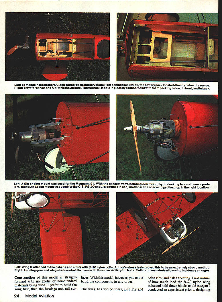
- Install battery pack and servos just behind the firewall; battery pack sits below the servos. Fuel tank is held by rubber bands and foam packing at front and back.
- The left engine mount shown is a Sig mount used for the Magnum .91; the Edson mount was used for .60, .75 and .90 engines (use a spacer as needed to position the prop).
- The wing is attached to the cabane struts with 1/4-20 nylon bolts. Landing-gear and wing struts use the same bolts. Collars on the rear struts allow slight wing incidence adjustment.
- Completely assemble the aircraft and verify no warps, correct alignment, and free operation of all controls. Extra effort here pays off later.
Covering and finishing
Covering and finish are a matter of personal preference. Traditional silk and dope is classic, but iron-on films or fabric and transparent MonoKote give a great look without dope fumes.
- Disassemble the aircraft and finish-sand all parts with 220-grit paper.
- Prime and color the cowl with an epoxy paint for durability.
- Cover the airframe with iron-on film or other covering. Transparent MonoKote lets you inspect internal structure.
Trimming and flying
After covering and reassembly, check and set control throws and CG before the first flight.
Recommended control throws (approximate):
- Elevator: 1/2 in. up, 1 1/16 in. down
- Ailerons: 1 5/16 in. up, 1 3/16 in. down
- Rudder: 1 1/2 in. left and right
- Make sure the center of gravity (CG) is within the designated range.
- Throttle setup: be able to fully stop the engine with stick and trim fully back.
- Use servo reversing if needed. Electronic mixing (ailerons/rudder) is useful for coordinated turns. The bomb-release can be operated from the retract channel if desired.
Radio and servos
Large quarter-scale aircraft require strong servos. For this Fokker D.VIII use servos with at least 45 oz.-in. torque. The author started with Airtronics No. 94394 (48 oz.-in.) and later installed Airtronics No. 99554 coreless ball-bearing heavy-duty servos (73.5 oz.-in.) on elevator, rudder, and ailerons.
The receiver antenna was routed inside the fuselage encased in the outer portion of a Gold-n-Rod for a clean installation; however, compatibility with other radio brands is not guaranteed.
Engine, props and test-running
- Recommended prop sizes:
- .60 four-cycle: 14 x 5 in.
- .75 four-cycle: 14 x 6 in.
- .90 four-cycle: 15 x 6 in.
- Become familiar with your four-cycle engine on a test stand; ensure reliable running at idle, mid-range, and top end before the first flight. Erratic ground running will not improve in the air.
- The author flew the Fokker with an O.S. FS75, O.S. FS90, and later a Magnum .91 (mounted semi-inverted and properly broken in), all with good results.
Final notes and experience
- Diagonal fuselage bracing yields a stiff, light rear end, eliminating the need for nose ballast.
- The Vortac bomb-release adds realism; accurate bombing proved more difficult than expected.
- After two seasons and about 100 flights, the author reports no damage to the airplane — a strong testament to the design's integrity.
This completes the build and flight notes for the quarter-scale Fokker D.VIII semiscale replica.
Transcribed from original scans by AI. Minor OCR errors may remain.

