
Fokker E.III Eindecker
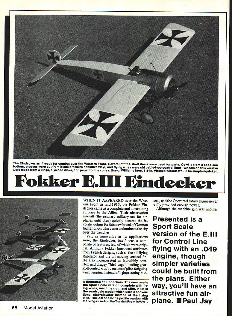
When it appeared over the Western Front in mid-1915, the Fokker Eindecker came as a complete and devastating surprise to the Allies. Their observation aircraft — the primary military use for airplanes until then — quickly became the favorite victims of this new breed of German fighter pilots who came to dominate the sky over the trenches.
The Eindecker itself was a composite of features, few of which were original. Anthony Fokker borrowed attributes from French designs, such as the all‑flying stabilator and the all‑moving vertical fin. He also incorporated an incredibly complex and draggy "bird‑cage" landing gear. Roll control was by means of pilot‑fatiguing wing warping instead of lighter‑acting ailerons.
The machine gun was another adaptation (in this case from an infantry weapon), but its practical interrupter mechanism was Fokker's most substantial contribution to aerial warfare. The mechanism enabled the gun to be mounted and fired from the front of the pilot, right behind the propeller, without risk of shooting the blades to splinters.
As a flying model, the Eindecker has never been very popular. The short‑nose/long‑tail combination tends to be tail‑heavy: the center of gravity (CG) is farther back than on many contemporary designs. Nevertheless, all three Control Line versions shown in the photos have proven stable in flight.
Several model versions are possible from the plans:
- Scale version (exact scale plan shown)
- Sport Scale / Control Line version (designed for an .049 engine)
- Semiscale / Ugly Stik and a simpler profile version (omit most landing gear parts, use a conventional horizontal tail and simpler tail skid)
The stabilator works fine on the model. It is free‑moving and, on the plans, the hinge location is placed more forward than full scale. This is necessary because the true scale hinge location places the center of pressure too far forward and can result in the tail flipping full‑up or full‑down in propwash.
Select balsa carefully for the fuselage and tail assembly. The CG will vary by version:
- Ugly Stik version used medium balsa for the fuselage and 3/32" medium balsa for the tail, producing a CG farther aft.
- Sport Scale model used soft 1/16" balsa for fuselage and tail; expect the CG roughly 1/2"–1 1/4" back from the wing leading edge depending on final construction.
If necessary, mount the wing slightly farther back to move the CG forward, at the expense of scale appearance.
Presented here is a Sport Scale Control Line E.III for an .049 engine. Simpler varieties may be built from the same plans. Either way, it makes an attractive and fun airplane. — Paul Jay
Materials / Tools to gather
- Two 1/16" x 3" x 36" soft balsa sheets (fuselage and tail)
- One 1/4" x 4" x 36" soft‑medium balsa (wing cheek pieces)
- 3/32" balsa scrap (nose doublers)
- Homemade compass cutter
- Landing gear wire parts
- Wheels: Williams Brothers vintage wheels (1‑1/2" dia. suggested) or make your own from hardware‑store O‑rings, 1/8" plywood disks, paper covers, and short 8‑32 aluminum screws
- Short 8‑32 aluminum screws (office‑supply source)
- Brass or copper rivets (to act as axle bearings; solder to end axle)
- Stiff paper for outer cone covers (cowling bands, wheel covers)
- Soft copper wire and rosin‑core solder
- Slow‑setting epoxy and cyanoacrylate (CyA) glue
- 2‑in. bellcrank with 6‑32 screw, washers, and nuts
- .020" scrap acetate (windscreen)
- 2‑in. piece of solid solder, fishing weight, or steel washers (wing tip weight)
- Four 3‑48 screws and blind‑mounting nuts
- Small hardware for mounting and rigging
- Safety goggles (for Dremel/Moto‑Tool work)
Parts
- One .062" x 36" music wire (stabilator joiner, L‑1)
- One .055" x 36" music wire (pushrod)
- One .020"–.025" x 36" music wire (lead‑outs)
- One .032" x 36" music wire (L‑2, L‑3, L‑4, L‑5, T‑1, T‑2, T‑3, cabane)
- One 1/8" x 6" x 12" plywood (firewall, L‑5, bellcrank and tail skid mounts, lead‑out guide)
- .062" I.D. x 2" aluminum tubing (stabilator pivot bearing)
- Two vintage wheels (see Materials above) or make-your-own wheel parts
- 1/16" balsa (planking, as required)
- 1/16" ply pieces, assorted small sheet balsa for cheek pieces, etc.
- Miscellaneous: copper rivets, small washers, solder, thin polyester/silk/nylon fabric for control-surface patches
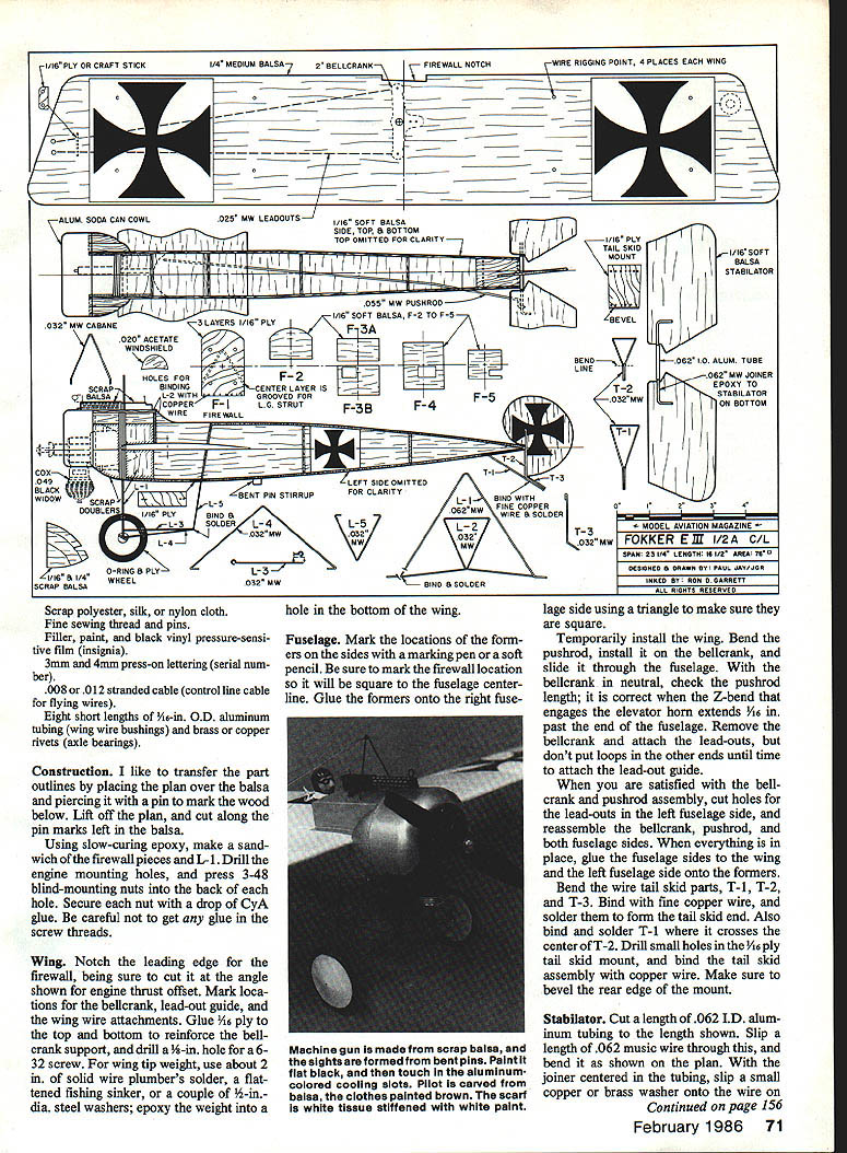
Construction
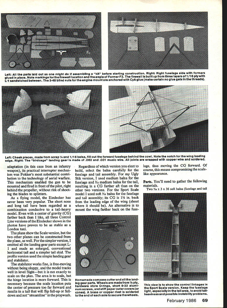
Transferring patterns and preparation
- Transfer part outlines by placing the plan over the balsa and piercing it with a pin to mark the wood. Lift the plan and cut along the pin marks.
- Using slow‑curing epoxy, sandwich the firewall pieces with L‑1. Drill engine mounting holes and press 3‑48 blind‑nut mounting nuts into each hole; secure each nut with a drop of CyA, taking care not to get glue in the screw threads.
Wing
- Notch the leading edge for the firewall at the angle shown for engine thrust offset.
- Mark locations for the bellcrank, lead‑out guide, and wing wire attachments.
- Glue 1/16" ply to top and bottom to reinforce the bellcrank support; drill a 1/8" hole for the 6‑32 screw.
- For wing tip weight, use approximately 2" of solid wire plumber's solder, a flattened fishing sinker, or a pair of 1/2"‑dia. steel washers; epoxy the weight into a hole in the bottom of the wing.
Fuselage
- Mark former locations on the fuselage sides and mark the firewall location square to the fuselage centerline.
- Glue the formers onto the right fuselage side using a triangle to ensure squareness.
- Temporarily install the wing. Bend the pushrod and install it on the bellcrank; slide it through the fuselage. With the bellcrank neutral, the Z‑bend that engages the elevator horn should extend about 1/16" past the end of the fuselage.
- Remove the bellcrank and attach the lead‑outs, leaving the outer loops until you fit the lead‑out guide.
- Cut holes for the lead‑outs in the left fuselage side, reassemble bellcrank and pushrod, then glue the fuselage sides to the wing and glue the left fuselage side onto the formers.
Tail skid and landing gear
- Bend the wire tail skid parts (T‑1, T‑2, T‑3). Bind with fine copper wire and solder to form the tail‑skid end. Bind and solder T‑1 where it crosses the center of T‑2.
- Drill small holes in the 1/16" ply tail skid mount and bind the tail skid assembly with copper wire; bevel the rear edge of the mount.
- Finish bending landing gear parts from .032" wire. Drill small holes through the firewall near the bottom; bind L‑2 in place with fine copper wire. Lace L‑5 to the 1/8" ply and glue this assembly to the fuselage bottom under F‑3B.
- Where L‑2 and L‑4 come together near L‑1 axles, wrap with copper wire and solder the joint. Bend loops in L‑3 so joints wrap around junctions; solder some joints at final assembly time.
- Spread epoxy along the bottom edge of the firewall to blend L‑2 and its wire wrapping; do the same for L‑5 and the tail skid. Pack the bottom of the fuselage from L‑5 forward to the firewall and add top decking in front of the cockpit.
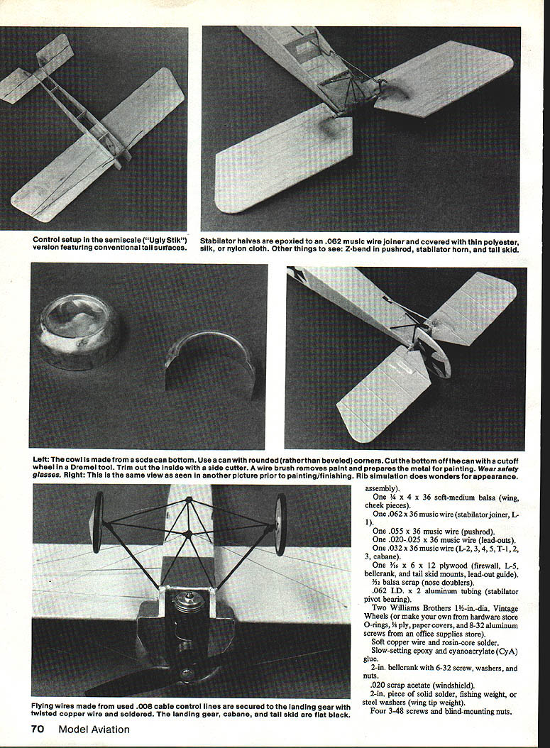
Stabilator
- Cut a length of .062" I.D. aluminum tubing for the bearing. Slip a .062" music wire through it and bend the wire as shown on the plan. With the joiner centered in the tubing, slip a small copper or brass washer onto the wire on each side of the tubing and solder (avoid getting flux inside the tubing). Leave clearance so the wire will rotate freely without sliding.
- Epoxy the stabilator halves onto the wire joiner using patches of sheer polyester, silk, or nylon fabric. Ensure both halves are level and not twisted.
- Make a stabilator horn from .032" music wire and epoxy it to the bottom of the left stabilator half (you may glue this and the wire joiner at the same time).
- Set the fuselage/wing assembly flat. Wiggle the stabilator horn onto the pushrod and hold the aluminum tubing bearing in place at the ends of the fuselage sides. The stabilator should be level with the wing when viewed head‑on; the leading‑edge distances from both stabilator halves to the wing trailing edge should be equal. If not, sand or slightly adjust the fuselage sides or wait until planking to twist the fuselage into alignment.
- Use CyA or 5‑minute epoxy to glue the stabilator bearing to the fuselage ends, being careful not to get glue inside the bearing.
- Epoxy the tail skid assembly in place and epoxy the joint between the tail skid mount and stabilator bearing.
- Plank the top and bottom of the fuselage with soft 1/16" balsa, applied cross‑grained, starting at the rear and working forward. Leave top decking forward of the cockpit and the area under the wing until later.
- Cut a slot in the bottom planking for the pushrod exit and bevel the rear edge of the top planking where it meets the stabilator bearing.
- Epoxy a small piece of sheer polyester (or silk/nylon) from the top of the fuselage around the bearing and down onto the tail skid mount (avoid getting glue in the bearing).
- Smear some epoxy onto the tip of T‑1 and into the slot in the fin, then slide the fin in place. Epoxy another piece of sheer fabric around T‑1 and the lower part of the fin. Put slight offset into the fin before the epoxy sets.
Firewall, cheek pieces, engine bay
- Test the firewall fit with the fuselage; cut slots in the fuselage sides as needed to clear the L‑1 struts. Epoxy the firewall square to the centerline and mate it with the offset notch in the wing leading edge.
- Cut fuselage side doublers from 3/32" balsa and epoxy them to the front and rear of the firewall; apply a thin coat of epoxy on the back of the firewall.
- Glue on top decking in front of the cockpit. Coat the engine bay with a thin layer of epoxy for fuel‑proofing (avoid getting epoxy in screw threads).
- Make cheek pieces to fit on either side of the nose from scrap 1/4" and 1/16" balsa. The front of the fuselage is circular and conforms to the cowl diameter.
Wheels and cowl
- Wheels: make from hardware‑store O‑rings, 1/8" plywood disks, short 8‑32 aluminum screws, stiff paper outer covers, and copper rivets as axle bearings. Drill holes the length of the screws, insert copper rivets, and secure screw/rivet/O‑ring with CyA. Paint the back side and paper covers, solder the copper rivets to the axles, and cement paper covers to the outside. Alternatively, use Williams Brothers vintage wheels to save time.
- Cowl: make from a drink can with a rounded bottom. Remove paint with a wire brush in a Dremel Moto‑Tool, use a cut‑off wheel to remove the bottom of the can and cut the segment from the bottom cowl circumference, and use a router bit to cut the indented bottom. Wear safety goggles. Epoxy the cowl to the front of the fuselage with a 1/8" overlap. The band around the cowl can be stiff paper or Tyvek about 1/8" wide; secure with CyA or epoxy.
Rigging and flying wires (flying wires and cabane)
- Drill holes through the top of the fuselage into the firewall and mount the .032" music‑wire cabane; apply a drop of CyA where each end enters the top of the fuselage.
- Drill 3/16" holes in the wings where shown and CyA short lengths of 1/16" O.D. aluminum tube into each hole to act as bushings.
- Wrap two turns of copper wire loosely around the cabane and also around junctions of L‑2/L‑3 and L‑3/L‑4/L‑5.
- Cut the cable into four pieces, each long enough to run two cables from the L‑2/L‑3 junction, through the wing holes, around the cabane top loop, and back. Do the same for the junction at L‑3/L‑4/L‑5 to the opposite wing.
- Wrap the copper wire tightly around the flying wires at the top of the cabane and solder. Tightly wrap and solder at L‑2/L‑3 and L‑3/L‑4/L‑5 junctions. Put a drop of CyA where each wire slips through a wing bushing to finish the flying wires.
- Finally, paint the landing gear, tail skid, and cabane flat black (do not paint the wing wires).
Finishing and detailing
- Keep the finish lightweight aft of the CG.
- To simulate ribs on wings and tail: apply a coat of filler, glue narrow paper strips (or sewing thread) with a dab of CyA at leading and trailing edges, apply more filler, and sand in the direction of flight.
- Finish colors: for the Sport Scale E.III, a cream‑colored paint (mixed from yellow, red, and white polyurethane) simulates varnished linen. Cowl, cheeks, fuselage front, and forward top decking finished with aluminum paint.
- Insignia: paint white squares first, mask white areas on wings and fuselage, seal tape edges with clear polyurethane, then apply cream paint. Black crosses can be cut from self‑adhesive vinyl. Use a compass cutter for curved pieces (2‑1/4" radius for wing, 7/8" for fuselage, 1‑1/8" for fin).
- Serial number: press‑on lettering 3–4 mm high to match a museum example if desired.
- Machine gun: make from scrap balsa with bent pins for the gun sight; paint flat black and use aluminum/gray paint for cooling slots.
- Windscreen: cut from .020" acetate and glue into a slot in the top decking.
- Pilot: carve from balsa and paint (example: brown‑maroon clothing, pink skin, goggles black). Scarf: white tissue stiffened with white paint. Stirrup loops can be bent from straight pins painted flat black.
Control setup
- Sport Scale version: keep fuselage light; follow plans for control linkages and stabilator neutral position. Use some "eyeball" judgment to set neutral stabilator; check equal up‑and‑down movement.
- Semiscale/Ugly Stik version: features conventional tail surfaces and conventional control linkages.
Final assembly and weights
- Check tail skid assembly fit and trim as necessary; epoxy in place.
- When finished, total weight with engine should be about 7 oz. The CG should be no farther aft than 1/4" from the wing leading edge; aim for the CG range noted earlier depending on version and construction.
- Handle the model carefully during assembly; there is little structure holding the stabilator until final planking and gluing.
Flying
- Choose a windless day and a smoothly paved flying site well away from power lines.
- Do not "horse" the model off. Let it roll forward a few yards, then ease in a bit of up control. The Eindecker should rotate smoothly and be very stable in flight thanks to its long tail moment.
- When the engine cuts, the model should track straight ahead and gradually lose altitude with no tendency to dive.
- Aerobatics: expect wingovers and inverted flight; loops are possible only with very light models (around 5 oz.). Avoid aggressive Immelmanns and excessive abrupt maneuvers.
References
- Profile Publication #38
- The Book of Warplanes, Kenneth Munson
- Aces of the Air, Francis K. Mason (notes on an E.I flown by Max Immelmann)
- Fighter Aircraft of the 1914–1918 War
- Aeromodeller/Argus Specialist Publications Plan #3056 (available from plan distributors)
- Warplanes and Air Battles of World War I, ed. Bernard Fitzsimons
- The Encyclopedia of German Military Aircraft, Bryan Philpott
Notes:
- Different sources disagree on full‑size dimensions (wingspan, chord). Scaling directly from full‑size drawings can be inconsistent; this is a Sport Scale model project — the main purpose is fun.
Transcribed from original scans by AI. Minor OCR errors may remain.

