
Fokker Spin III
By David Haught
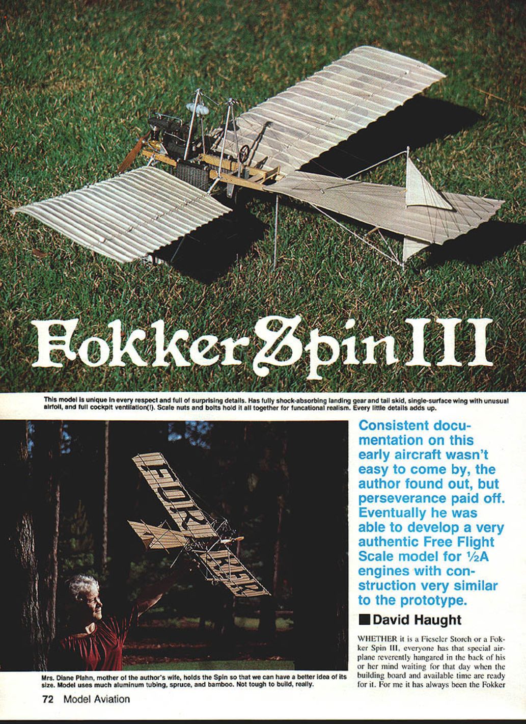
Whether it is a Fieseler Storch or a Fokker Spin III, everyone has that special airplane reverently hangared in the back of his or her mind waiting for that day when the building board and available time are ready for it. For me it has always been the Fokker Spin III.
Bits and pieces of Fokker Spin information have been collected by me since I was age 10, and I've carried the tattered magazine pictures and meager three-views with me ever since. As my building skills developed, so did my interest in building the Spin III. As with most dream machines, I wanted to do the job as best I could, which meant I would need good documentation. This was something that was to frustrate the project for many years.
Beyond the lack of congruent scale data, other obstacles began to loom. Simplicity and ruggedness were the rule for all the scale models I have had success with. Here in the Northwest, a model like the fragile Spin would be faced with possible collisions with sagebrush and canals on the flying site—not too nice an environment to raise a model covered with wires. But it came to the point where the obsession to build it overcame the practical considerations.
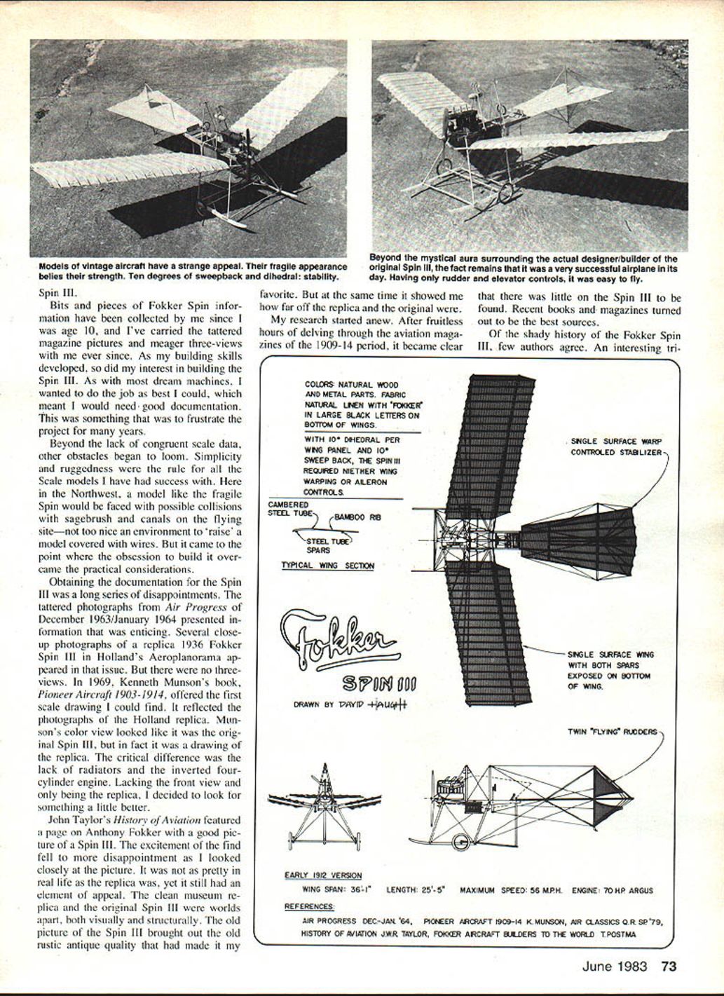
Obtaining documentation for the Spin III was a long series of disappointments. The tattered photographs from Air Progress (December 1963/January 1964) presented information that was enticing. Several close-up photographs of a replica 1936 Fokker Spin III in Holland's Aeroplanorama appeared in that issue, but there were no three-views. In 1969, Kenneth Munson's Pioneer Aircraft 1903-1914 offered the first scale drawing I could find. It reflected the photographs of the Holland replica. Munson's color view looked like the original Spin III, but in fact it was a drawing of the replica. The critical difference was the lack of radiators and the inverted four-cylinder engine. Lacking the front view and only being the replica, I decided to look for something a little better.
John Taylor's History of Aviation featured a page on Anthony Fokker with a good picture of a Spin III. The excitement of the find fell to more disappointment as I looked closely at the picture. It was not as pretty in real life as the replica was, yet it still had an element of appeal. The clean museum replica and the original Spin III were worlds apart, both visually and structurally. The old picture of the Spin III brought out the rustic, antique quality that had made it my favorite. At the same time it showed me how far off the replica and the original were.
My research started anew. After fruitless hours delving through the aviation magazines of the 1909–1914 period, it became clear that there was little on the Spin III to be found. Recent books and magazines turned out to be the best sources.
Of the shady history of the Fokker Spin III, few authors agree. An interesting trio of names—Fokker, Lt. Von Daum, and Mr. Godecker—each contributed something to the final design. In some combination, the Spin III was conceived, designed and built. Being only a two-control airplane and inherently stable, the Spin III was popular as a trainer. One photograph of an early flying school showed over 15 Spins on the field. Since it was built in large quantities, the chances of them all being exactly the same are quite slim.
Just which version of the Spin to build became the decision I had to make. I've found photographs of six different Spin IIIs, all described as "the original." When frustration almost cancelled the project, Air Classics (Spring 1979 Quarterly) crossed my desk. Eldon Quick's article brought a wealth of information to light. Several photographs and a series of neat scale drawings at first looked like I had what I wanted. While many points of the presentation were superb, there were also many problems—his version of the Spin III was not the one shown in my pictures. I decided that this was the last straw.
It was only after piling all the data I had on the Spin III into one heap and sifting it by the hour that I came up with a few consistencies that would work together. The key was the heading picture in Quick's article and the artist's rendering of the Spin III. There it was in all its glory—the original Spin III. The two items pulled all the loose ends together. It was all there: the long stabilizer, twin forward cabanes, upright four-cylinder engine, and the side-mounted radiators. After years of frustration, the formula was pieced together. The plans were drawn in a week. I feel this is as true a representation of the Spin III as research this far can produce.
The Spin III was then built in various sizes to experiment with the force layout of the design. It was built in Peanut Scale size, a 26-in. span CO-2 size, and finally the full-size model you see here. All three versions were quite successful.
The design cannot help but be stable with 10 degrees of dihedral and 10 degrees of sweepback. A fellow modeler and I have been building scale models of the same vintage and scale to compete against each other every year. Greg Davis built a series of Ertrich Taubes, and I built the series of Fokker Spins. It is a lot of fun to see them flying together at the same contest.
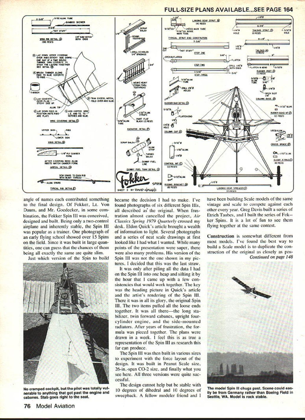
Construction is somewhat different from most models. I've found the best way to build a scale model is to duplicate the construction of the original as closely as possible. As a result, the Spin III is almost 90% aluminum tube and 10% wood. This also means working with new materials in new ways. The builder should not be discouraged, as the Spin III builds quite fast.
Tools and materials
- Tools:
- Small tubing cutter (very helpful)
- Set of small metal files of various shapes
- Set of small needle-nose pliers
- Materials and tips:
- Aluminum tubing (try to get 36-in. lengths; they are handier and cheaper than 12-in. lengths)
- Rear portion of wing ribs formed from bamboo strips (shish-kebab skewers are a convenient source)
- If skewers aren't available, use .032 sq. spruce and sand it round
- Model railroad 000 and 00 nuts, bolts and washers (the most expensive item)
- Coverite fabric for covering
All in all, the Spin III will not be any more expensive than a conventional scale model, and it will be stronger and far more realistic.
Stabilizer and rudders
The stabilizer is the best place to start. All the pieces are spruce strip that is sanded round, glued in place, and then each joint is wrapped with thread for realism and extra strength. The rearward edges of the "ribs" are notched for the wire trailing edge. Epoxy-coat all of the joints and set aside to cure.
The rudders give you a chance to try working with the aluminum tubing. Take care not to crimp the tube while bending it. For small sizes of tubing it may help to slide a strip of solder into the tube before bending; bend the tube, then remove the solder. Start each bend slowly, working it into shape a little at a time. File the ends of the tubing to fit the rudder spar tube, and join them together with cyanoacrylate (CYA) glue. Add a small amount of epoxy to each joint for added strength.
Cut the tube and form the rudder post, braces, and tail skid. Drill the hole through the stabilizer for the rudder post. Epoxy the stabilizer to the fuselage frame; block it up to form the angle of incidence shown on the plan. Sew the joint with heavy black thread. After it has set, assemble the rudders, rudder post, and braces. Align the assembly carefully on the work board, and add the brace wires. All the brace wires are important, so make sure they all fit taut and do not warp the stabilizer.
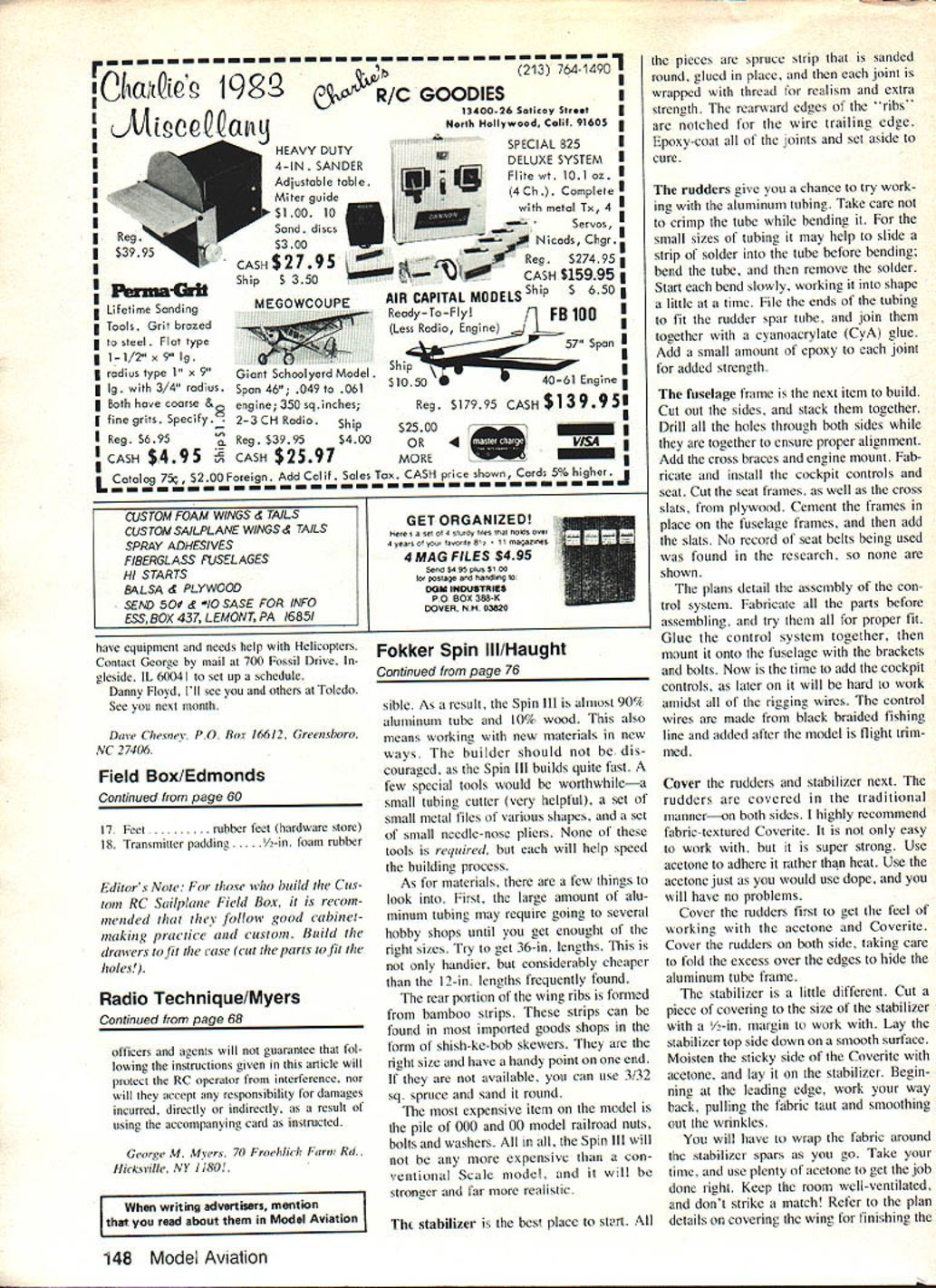
Fuselage and cockpit
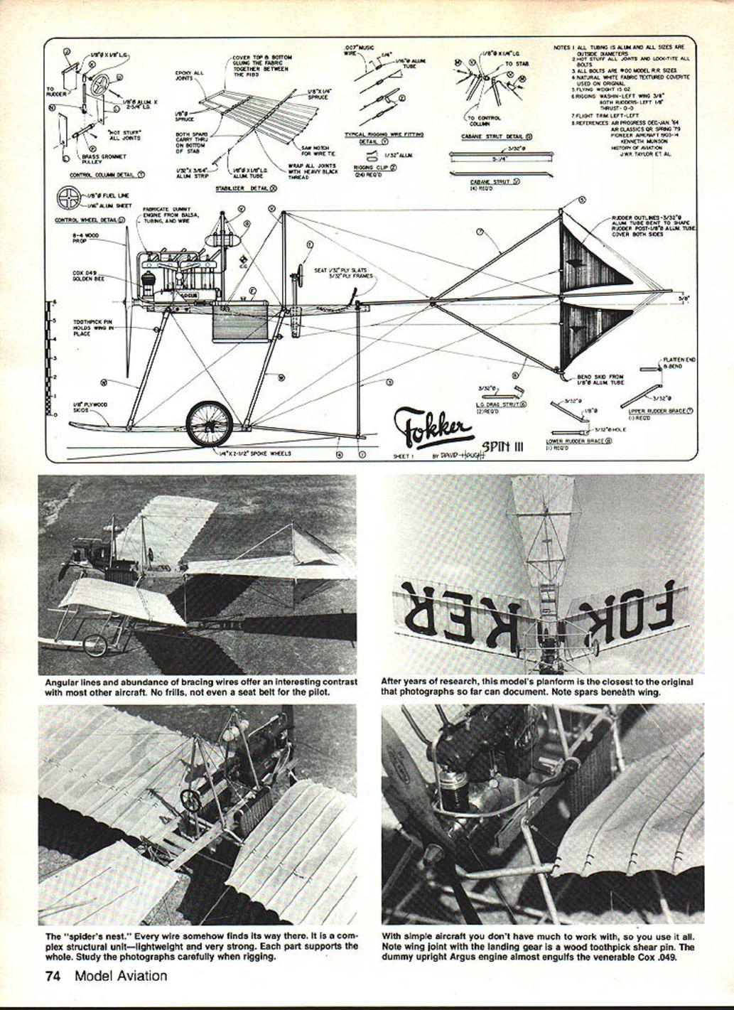
The fuselage frame is the next item to build. Cut out the sides, and stack them together. Drill all the holes through both sides while they are together to ensure proper alignment. Add the cross braces and engine mount. Fabricate and install the cockpit controls and seat. Cut the seat frames and the cross slats from plywood. Cement the frames in place on the fuselage frames, and then add the slats. No record of seat belts being used was found in the research, so none are shown.
The plans detail the assembly of the control system. Fabricate all the parts before assembling, and try them all for proper fit. Glue the control system together, then mount it onto the fuselage with the brackets and bolts. Now is the time to add the cockpit controls, as later on it will be hard to work amid all of the rigging wires. The control wires are made from black braided fishing line and are added after the model is flight-trimmed.
Covering
Cover the rudders and stabilizer next. The rudders are covered in the traditional manner—on both sides. I highly recommend fabric-textured Coverite. It is not only easy to work with, but it is super strong. Use acetone to adhere it rather than heat. Use the acetone just as you would use dope, and you will have no problems.
Cover the rudders first to get the feel of working with acetone and Coverite. Cover the rudders on both sides, taking care to fold the excess over the edges to hide the aluminum tube frame.
The stabilizer is a little different. Cut a piece of covering to the size of the stabilizer with a 1/2-in. margin to work with. Lay the stabilizer top side down on a smooth surface. Moisten the sticky side of the Coverite with acetone, and lay it on the stabilizer. Beginning at the leading edge, work your way back, pulling the fabric taut and smoothing out the wrinkles.
You will have to wrap the fabric around the stabilizer spars as you go. Take your time, and use plenty of acetone to get the job done right. Keep the room well-ventilated and don't strike a match! Refer to the plan details on covering the wing for finishing the trailing edge. Let the stabilizer dry for a good hour, and then trim off any excess fabric.
Covering the top is not so tough. Lay the acetone-dampened fabric onto the stabilizer, and work out the wrinkles. Fold over and glue the excess on the edges. After the cement has set, go back and brush acetone over the top surface; press the top and bottom surfaces together between the spars and ribs. Set aside to dry.
Landing gear
The landing gear is the key to the entire aircraft in structural terms. Study the steps on the plan for making the landing gear struts. The ends of each strut are reinforced from within with an inside tube sleeve. Form all four struts, then drill the holes as accurately as possible. It is a good idea to make a small jig to ensure proper spacing for all the holes in the four struts. If they are not evenly spaced, the rigging will pull the structure out of square and cause trim problems later.
Saw the skids from plywood, stack the skids, and drill the holes in both at the same time. Make an extra set of skids as they are quite vulnerable to breakage in rough landings. Make up all the remaining landing gear parts and cabane struts, and install them as per the plans. The last step for the landing gear and cabanes is the rigging. All the wires should be taut and of equal tension to prevent distortion and provide adequate strength.
Locate a set of spoked wheels, and fabricate all the axle parts. The axle assembly is designed to be shock-absorbing, and so is the tail skid. Study the pictures and plans closely to see where all the parts go.
Wings and rigging
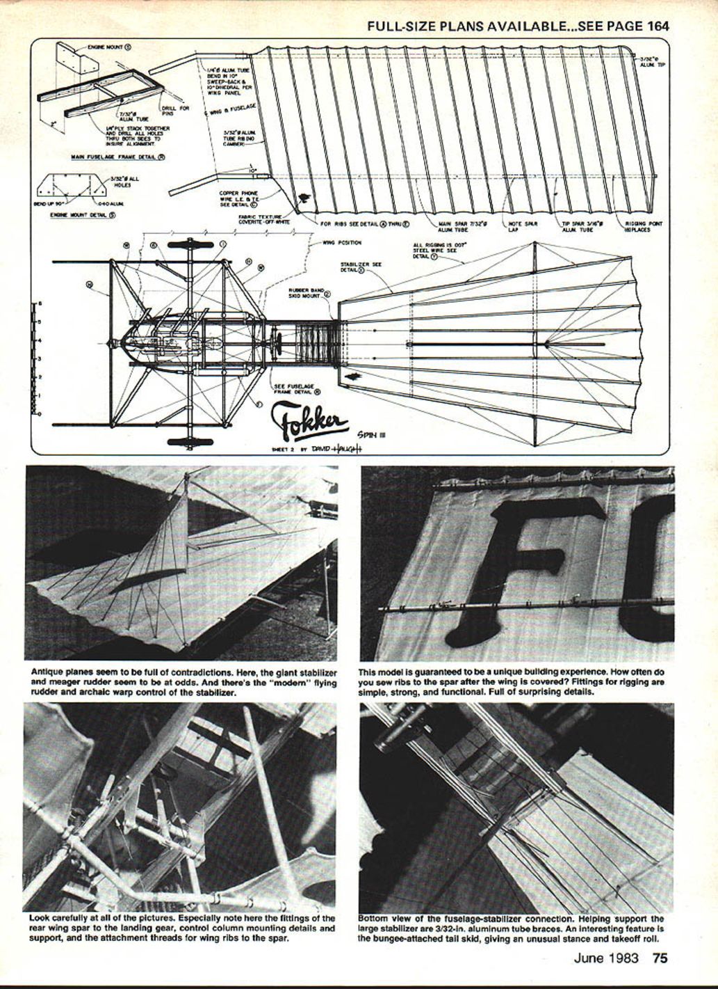
The wings are next. Study the steps shown on the plan carefully. Begin by making the flat ribs. This is the most unconventional part of the design. The wings are built sparless and flat, covered, and then the camber is added to the ribs. Finally, the spars are added. Each rib-spar crossing is sewn together using heavy black thread. Look over the pictures carefully. The real Spin III used U-bolts to anchor the ribs to the spars. Also note on this version, as on the original Spin III, that both spars run under the wing surface.
Bend the aluminum tube wing joiners carefully. When joined, the wings should have 10 degrees of sweepback and 10 degrees of dihedral per panel.
You will note on the side view drawing how toothpicks are used as alignment pins to mount the wing assembly to the landing gear struts. Block up the wing with the fuselage in place. Take time to align the two with proper wing incidence and dihedral. Clamp the wing in place; drill the pilot holes for the wood pins, and insert them. These pins will hold the wings in place securely, but will also give way in case of a crash, minimizing structural damage.
The wing bracing wires can now be made and installed. Do this in pairs—top and bottom for both wings. In this way the stresses can be kept to a minimum, eliminating unwanted warps. When setting up the assembly for rigging, don't forget to set up the proper wing wash-in. The wires are functional, so take time to set it up right.
Final assembly, balance and flight trim
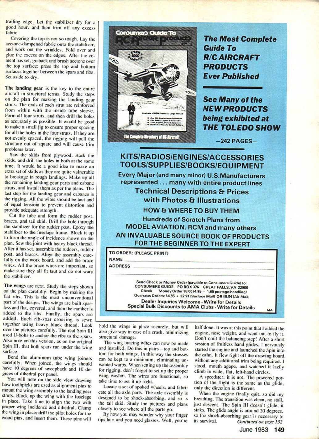
By now you may wonder why your fingertips hurt and you need glasses. Well, you're half done. At this point add the engine, nose weight, and go out to fly it. Don't omit the balancing step! After a short session of fruitless hand glides, start the engine and launch the Spin into calm air. It should fly right off the drawing board without any additional trim being required. It will lazily climb in wide, flat, left-hand circles.
A speedster it is not. The powered portion of the flight is much like the glide, only the direction is different. When the engine finally quits, the transition is clean—no stall—just descent. The Spin III doesn't glide; it sinks. The glide angle is around 20 degrees, so the shock-absorbing gear is necessary to its survival.
The Spin III handles wind well. The combination of sweepback, dihedral, and low center of gravity makes it very stable. I caution you, however, when trimming and flying vintage-type models, to watch the amount of power you try to fly them on. Use as little power as possible to get the model to climb slowly. Excessive speed on this type of aircraft causes radical flight patterns.
I've been using a Cox .049 engine with a wood 8x4 propeller, and I have had good results. The engine will not turn that propeller too fast. A Davis Diesel conversion was used at one point very successfully.
Maintenance, logging and detailing
If you haven't tried it before, it is a good idea to keep a flight log book on your Spin III. By recording fuel amounts, flight times, flight patterns, and weather conditions, you will be able to closely predict future flights. The Fokker's rigging should be inspected and repaired regularly to maintain proper trim and strength. The vibration of the engine and occasional snags from sticks on landing will tend to loosen the rigging and the nuts and bolts. This may allow the model to go out of trim. The log book will tell you where everything should be before each flight.
Once trimmed for flight, you can spend as much time detailing the Spin III as you wish. The dummy engine, fuel tank, and so on can be made from wood and tubing. They add a lot of realism as would a pilot. For detailing and documentation, the resources listed on the plans are worth looking into. Check the library; it may unexpectedly turn up something.
I hope you will try the Spin III. If not, use it as inspiration to build that one special model you've always wanted. It's worth all the time you put into it as you watch it circle overhead.
Transcribed from original scans by AI. Minor OCR errors may remain.

