
THE FOKKER T-2
Tom Stark
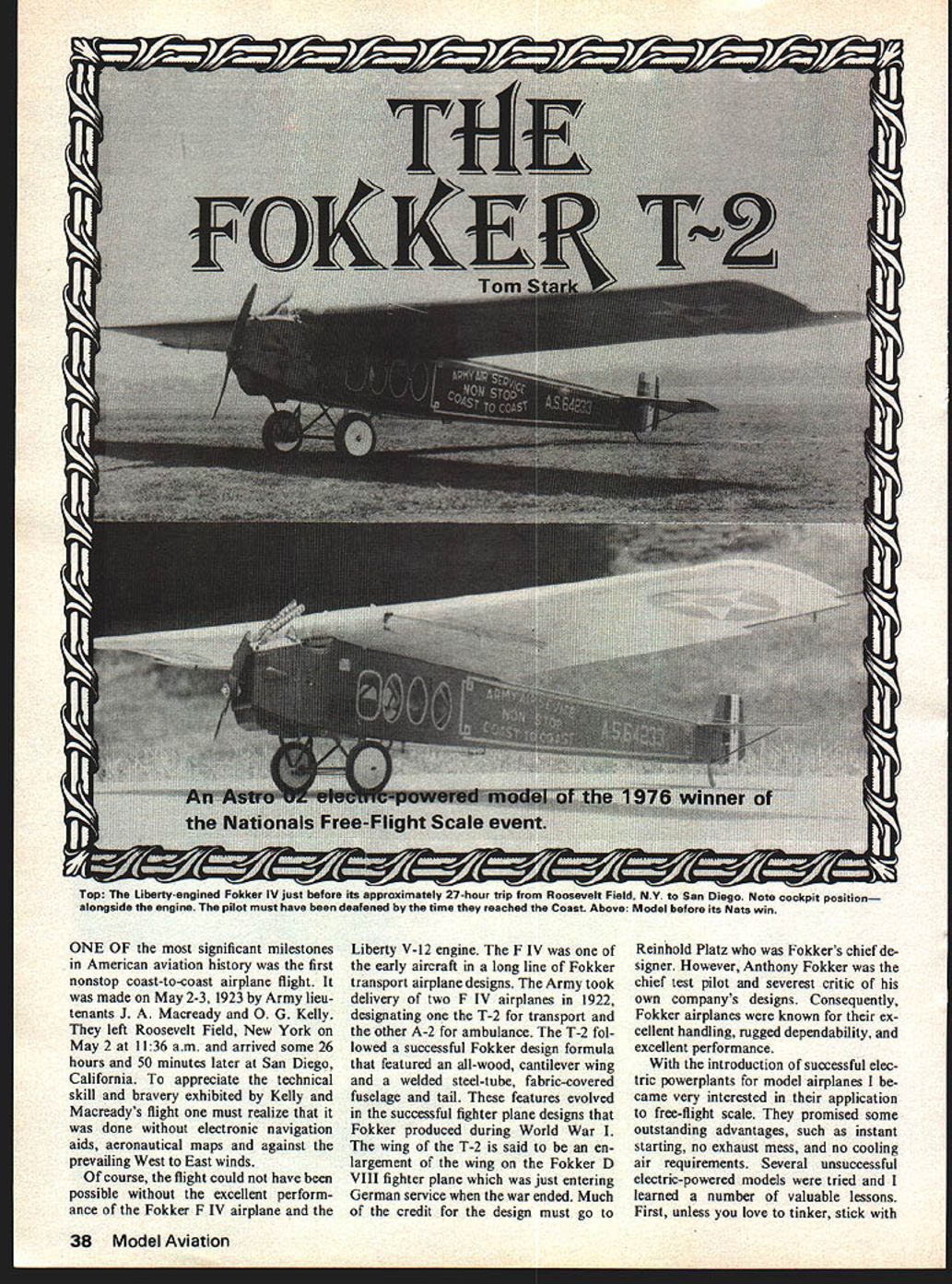
ONE OF the most significant milestones in American aviation history was the first nonstop coast-to-coast airplane flight. It was made on May 2-3, 1923 by Army lieutenants J. A. Macready and O. G. Kelly. They left Roosevelt Field, New York on May 2 at 11:36 a.m. and arrived some 26 hours and 50 minutes later at San Diego, California. To appreciate the technical skill and bravery exhibited by Kelly and Macready's flight one must realize that it was done without electronic navigation aids, aeronautical maps and against the prevailing West to East winds.
Of course, the flight could not have been possible without the excellent performance of the Fokker F IV airplane and the Liberty V-12 engine. The F IV was one of the early aircraft in a long line of Fokker transport airplane designs. The Army took delivery of two F IV airplanes in 1922, designating one the T-2 for transport and the other A-2 for ambulance. The T-2 followed a successful Fokker design formula that featured an all-wood, cantilever wing and a welded steel-tube, fabric-covered fuselage and tail. These features evolved in the successful fighter plane designs that Fokker produced during World War I. The wing of the T-2 is said to be an enlargement of the wing on the Fokker D VIII fighter plane which was just entering German service when the war ended. Much of the credit for the design must go to Reinhold Platz who was Fokker's chief designer. However, Anthony Fokker was the chief test pilot and severest critic of his own company's designs. Consequently, Fokker airplanes were known for their excellent handling, rugged dependability, and excellent performance.
With the introduction of successful electric powerplants for model airplanes I became very interested in their application to free-flight scale. They promised some outstanding advantages, such as instant starting, no exhaust mess, and no cooling air requirements. Several unsuccessful electric-powered models were tried and I learned a number of valuable lessons. First, unless you love to tinker, stick with well-engineered model aviation powerplants on the market; they will give the performance promised in the advertisements. Second, don't take short cuts in the battery charging system. A dry lantern battery will not charge flight batteries to their full potential. The powerplant won't reach its potential unless a wet-cell battery charging system is used and recommended instructions followed. Lastly, electric powerplants do not have the power-to-weight capabilities of regular IC glow-plug engines.
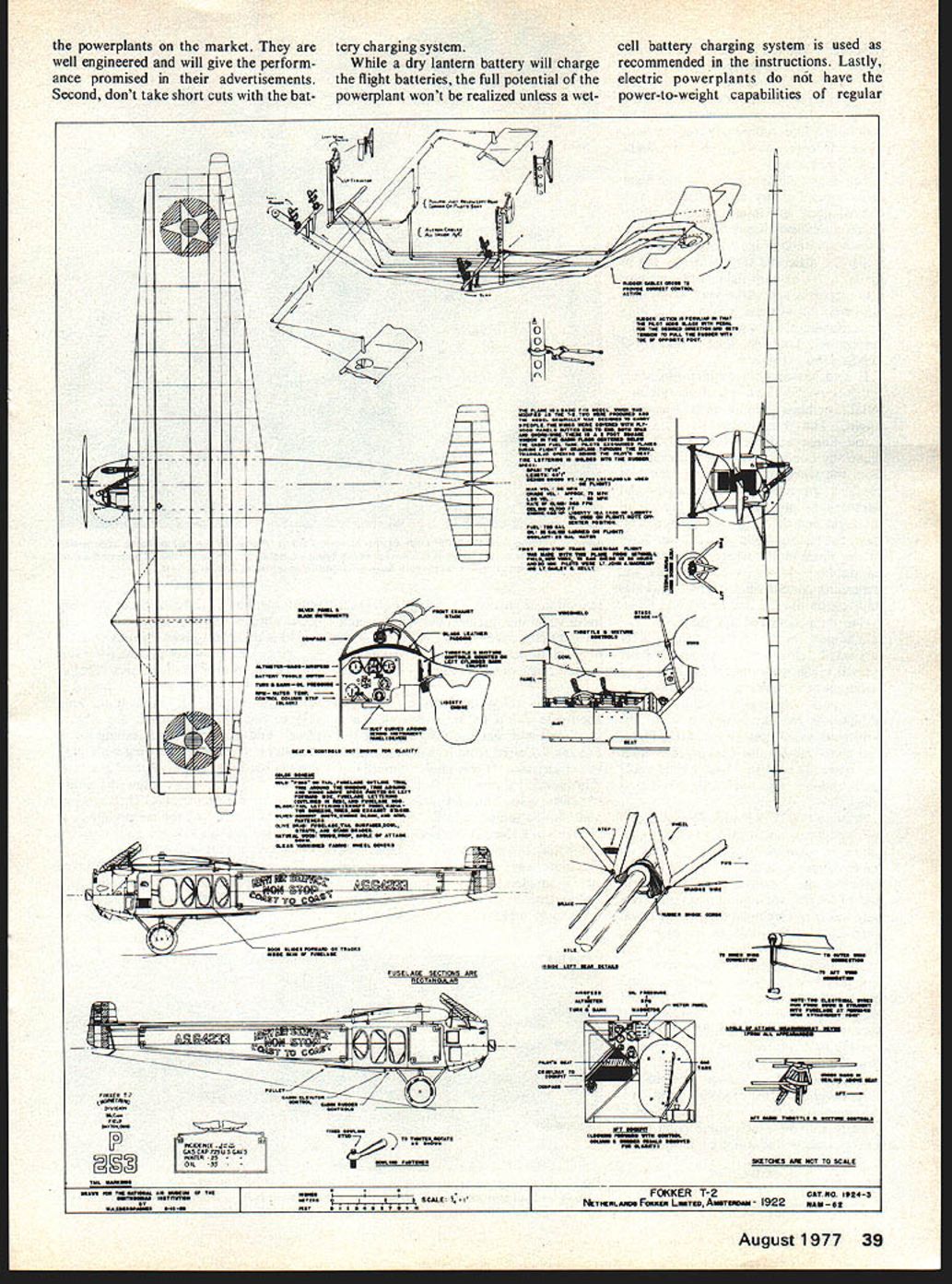
Construction techniques perfectly satisfactory for .049-powered models are probably too heavy for an electric-powered model. Generally electric-powered models should be built like rubber-powered models if they are to do well in free-flight scale competition. Scale judging rules for free-flight scale demand very detailed models—colored dope, interior details—which means relatively heavy models. However, few real airplanes suitable for electric free-flight scale generally fall into the category of ultra-light airplanes: pioneer airplanes, early very long-range airplanes, airplanes with high power loadings (i.e., lot of weight per horsepower available). The Fokker T-2 falls into that category and also has another distinct advantage—availability of proof-of-scale material. The book Smithsonian Annals Flight: First Nonstop Coast-to-Coast Flight, Historic T-2 Airplane by Louis S. Casey is still available from the Government Printing Office and contains excellent 3-view drawings, photographs plus complete history of the flight and the airplane's development. After the historic flight the T-2 was flown to the Smithsonian where it is currently on display. Numerous other books and magazines contain photographs, drawings and text on the T-2 and its historic flight.
One thing that bothered me about the T-2 subject for free flight is its very small stabilizer. Consequently I built a small glider scale model of the T-2 to determine
The Fokker T-2
First, unless you love to tinker, stick with well‑engineered model electric powerplants on the market. They are well engineered and will give the performance promised in their advertisements.
Second, don't take short cuts with the battery charging system. While a dry‑lantern battery will charge the flight batteries, the full potential of the powerplant won't be realized unless a wet‑cell battery charging system is used as recommended in the instructions.
Lastly, electric powerplants do not have the power‑to‑weight capabilities of regular glow‑plug engines. Construction techniques perfectly satisfactory for glow‑powered models are probably too heavy for an electric‑powered model. Generally, electric‑powered models should be built like rubber‑powered models.
Free‑flight scale can pose problems. Scale judging rules for free‑flight scale demand very detailed models—colored dope, interior details—which means relatively heavy models. However, few real airplanes suitable for electric free‑flight scale generally fall into the category of ultra‑light airplanes: pioneer airplanes, early very long‑range airplanes, airplanes with high power loadings (i.e., a lot of weight per horsepower available). The Fokker T‑2 falls into that category and also has another distinct advantage—availability of proof‑of‑scale material. The book Smithsonian Annals: Flight — First Nonstop Coast‑to‑Coast Flight, Historic T‑2 Airplane by Louis S. Casey is still available from the Government Printing Office and contains excellent 3‑view drawings and photographs plus a complete history of the flight and the airplane's development. After the historic flight the T‑2 was flown to the Smithsonian, where it is currently on display. Numerous other books and magazines contain photographs, drawings and text on the T‑2 and its historic flight.
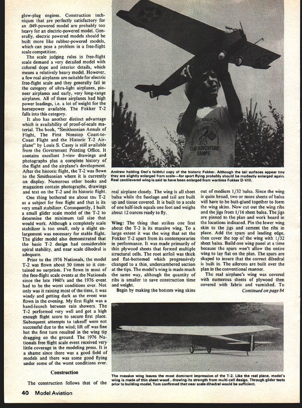
One thing that bothered me about the T‑2 subject for free flight is its very small stabilizer. Consequently I built a small glider scale model of the T‑2 to determine determine the minimum tail size that would work. Although a completely scale stabilizer is too small, only a slight enlargement was necessary for stable flight. The glider model also demonstrated that the basic T‑2 design had considerable spiral stability, and near-scale dihedral is adequate.
Prior to the 1976 Nationals, the model T‑2 was flown about 50 times so it contained no surprises. I've flown in most of the free‑flight scale events at the Nationals since the late 1960's and the 1976 event had to be the worst conditions ever. Not only was it raining most of the time, it was windy and getting dark as the event was flown in the evening. My first flight was a hand-launch between rain showers. The T‑2 performed very well and got a high enough flight score to secure first place. Subsequent attempts to take off were not successful due to the wind; lift off was fine but the first turn resulted in the wing tip dragging on the ground. The 1976 Nationals free flight scale event received very little coverage in the modeling press. It is a shame since there was a good field of models and there was some good flying under some of the worst conditions ever.
Construction
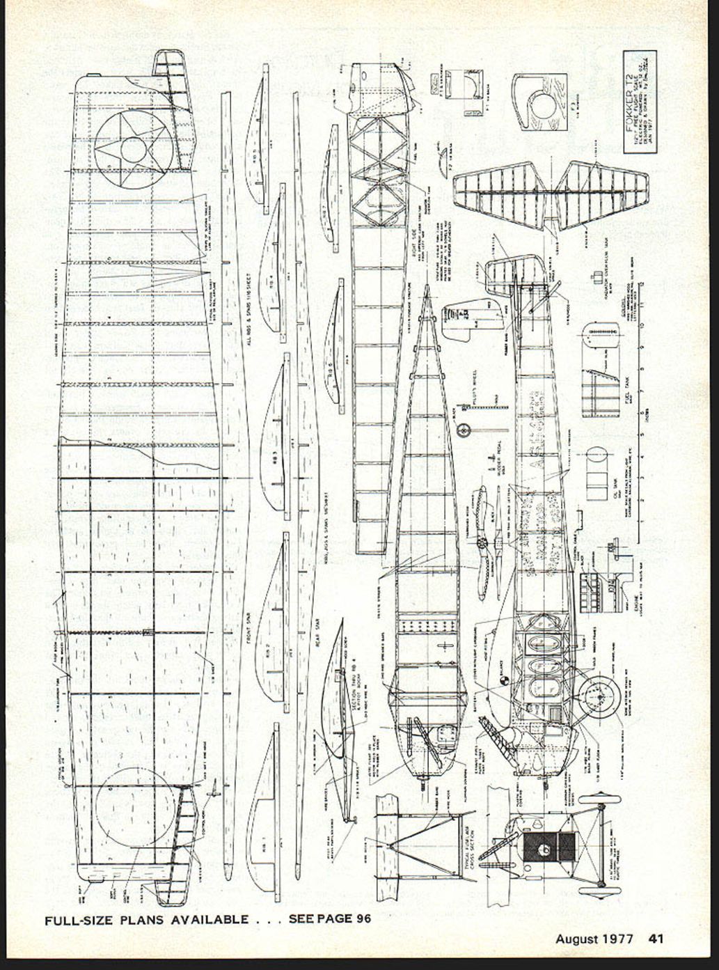
The construction follows that of the real airplane closely. The wing is all sheet balsa while the fuselage and tail are built up and tissue covered. It is built to a scale of one half-inch equals one foot and weighs about 12 ounces ready to fly.
Wing
The thing that strikes one first about the T‑2 is its massive wing. To a large extent it was the wing that set the Fokker T‑2 apart from its contemporaries in performance. It was made primarily of thin plywood sheets that formed multiple structural cells. The root airfoil was thick and flat-bottomed which progressively changed to a thin, undercambered section at the tips. The model's wing is made much the same way, although the quantity of ribs is smaller to save construction time and weight.
Begin by making the bottom wing skins out of medium 1/32 balsa. Since the wing is quite broad, two or more sheets of balsa will have to be butt-glued together to form the wing skins. Now cut out the wing ribs and the jigs from 1/16 sheet balsa. The jigs are pinned to the plan and work board in the locations indicated. Pin the lower wing skin to the jigs and cement the ribs in place. Add the spars and leading edge, then cover the top of the wing with 1/32 sheet balsa. Build one wing panel at a time because the spars won't allow the entire wing to lay flat on the plan. The spars are shaped to ensure that the correct dihedral is built in. The ailerons are built over the plan in the conventional manner.
The real airplane's wing was covered with numerous sheets of plywood then covered with fabric and varnished. To (Continued) simulate the different shades of coloring of the plywood sheets the wing can be lightly stained in a random pattern of rectangles that are the scale plywood sheet size. Now dope on thin strips of Silkspan where shown on the plan to simulate the lap joints of the real airplane's fabric covering. The entire wing can now be covered with white Japanese tissue and given two or three coats of clear dope.
Fuselage: Construction is old-time built-up but with a few unusual wrinkles. First of all, the two sides aren't identical. The basic structure of the real airplane is visible through the large windows, so to preserve the scale appearance the model duplicates the location of the structural members. Instead of building one side directly on top of the other, as is traditional, each side is built separately on different plan views. Also, since the real airplane was built of steel tubing, the model structure in the cabin area, visible through the windows, should be round and painted gray. Rounded 1/8 sq. balsa was used in the original model. While the visual effect is good, it could be improved by using 1/16 hardwood dowels for the uprights and other structure in the cabin area—but not the longerons. After the sides are completed, join them at the rear and add the cross pieces. Kraft C clamps are excellent for this purpose and they help insure squareness.
The nose is built primarily of sheet balsa with thin aluminum covering on the top and bottom. The bottom covering is installed with very small wood screws so that it can be removed for access to the motor. A charging jack and switch can be installed in the bottom covering. Suitable aluminum for this purpose can come from clothes-drier ducts which are available at most hardware stores at a modest cost. The front radiator piece is thin plywood, held in place by a lip on the bottom cowl covering. The Astro 020 motor is held in is held in place by rubberbands that are held by hooks attached to the inside of the nose balsa side pieces. If a VL motor is used it can be screwed to former F3 but the hole in the former should be made slightly smaller to fit the motor.
The sides of the cabin area are covered with light cardboard, such as file folder or notebook separator material. The windows are cut into the cardboard covering. The fuselage should be covered with Silkspan tissue. On the real airplane the cowling was covered with metal. The sides of the cowling should be covered with thin plastic sheet, such as celluloid or clear plastic sheet about .010 or .015 inch thick. When painted, this makes an excellent simulation of metal covering. The cabin has a 1/32 sheet balsa floor which is stained wood color. The rest of the cabin area is painted light gray. The Astro Flight battery pack should be painted gray and set in a balsa box on the cabin floor. It is held in place with rubberbands attached to hooks on the cabin sides. In this location the battery approximates the size and location of the cabin fuel tank in the real airplane.
The landing gear is made of .064 and .040 music wire and is quite rigid. The spring action comes from the 3/32-in. brass tubing axle which is bound to the landing gear with white elastic thread. This springing is the same as used on the real Fokker T-2 and many other airplanes of that era. The landing gear built in this manner is not only realistic but has proven to be rugged.
The wing is held to the fuselage by rubberbands inside the fuselage. The fuselage section view on the plan shows how. There should be a hook on both wing spars and matching hooks attached to the fuselage structure. Split 1/8-in. dowel keys should be cemented to the wing and notches cut in, in appropriate places, on the top fuselage longerons so that the wing location does not shift. This method of wing attachment avoids any externally visible mounting parts and allows for wing movement on impact. It has proven to have been very trouble free in this model.
The tail surfaces are ordinary stick construction built on the plan and covered with Japanese tissue.
Finish: The fuselage and tail are given enough coats of clear dope to just fill the tissue and give a relatively smooth finish. Then they are painted olive brown. Although the color is specified as olive drab, airplanes of this era were much more brown than the greenish olive drab of World War II airplanes. To obtain a suitable color you can mix two parts of Aero Gloss camouflage tan with one part of earth brown.
The markings are applied now. Refer to the photographs for the location of the fuselage striping—which is gold. The lettering also is gold, as are the window frames. Vinyl self-stick shelf paper is an excellent material for making stencils for the lettering and the wing insignia.
Flying: My model balanced just about right without the need for ballast. However, if your model doesn't balance at the point shown on the plan, add ballast to achieve the correct center of gravity. Be sure that the tail surfaces are not warped. Set the control surfaces in the neutral position.
Hand-glide the model over tall grass and adjust the control surfaces as required for a smooth, straight, or slightly left turn glide. Next try a powered flight with a short battery charge that will give about ten seconds of full power. One different characteristic of electric power is that you get the same initial power regardless of the length of battery charging; the charging time determines the duration of powered flight.
The climb should be in a left turn. If the model stalls or turns to the right, adjust the thrust line and/or control surfaces to get a left turn under power. The ideal flight pattern for this model seems to be an open left turn under power and a straight glide or a slight right turn in the glide. Even though the T-2 has little dihedral it will right itself in the glide. The model can turn quite tightly under power, but such a tight turn isn't realistic.
While most of this article has described a competition type free-flight electric-powered scale model, the design is flexible enough for some other applications. For example, an .020 glow engine would work very well and would probably increase the performance due to its lighter weight. If you are not interested in contest flying the stabilizer could be enlarged about 15 percent for easier adjusting. The cabin area is quite roomy and could easily hold a radio control set. With an .049 glow engine and a light radio the T-2 would lend itself well to an RC for confined space flying.
Regardless of whether you build a duplicate of the electric-powered free-flight model, or one of the suggested modifications, you will be rewarded with a realistic flying replica of one of our most important historic airplanes. As the model cruises slowly but majestically overhead you will be reminded of one of the most inspiring feats in our American aeronautical heritage.
Transcribed from original scans by AI. Minor OCR errors may remain.

