
Fokker Universal
ONE OF THE more pleasurable pursuits of the flying scale enthusiast who prefers to "start from scratch," is the search for a design that seems to fulfill a number of requirements. Is it esthetically pleasing? Is it proportioned so as to have a reasonable chance of flying well, without excessive design distortion? Is it graphically pleasing in color and marking scheme? Finally, is it historically significant?
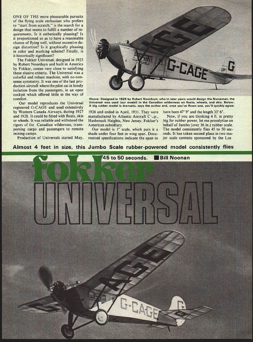
The Fokker Universal, designed in 1925 by Robert Noorduyn and built in America by Fokker, comes very close to satisfying these elusive criteria. The Universal was a colorful and robust machine, with no-nonsense symmetry. It was one of the last production aircraft where the pilot sat in lonely isolation from the passengers, in an open cockpit which offered little in the way of comfort.
Our model reproduces the Universal registered G-CAGE and used extensively by Western Canada Airways, during 1927 and 1928. It could be fitted with floats, skis or wheels. It was reliable and withstood the rigors of the Canadian wilderness, transporting cargo and passengers to remote mining camps.
Production of Universals started May, 1926 and ended in April, 1931. They were manufactured by Atlantic Aircraft Co., Hasbrouck Heights, New Jersey, Fokker's American subsidiary.
Our model is 1" scale, which puts it a shade under four feet in wing span. Documented specifications indicate the span to have been 47'9" and the length 33'6".
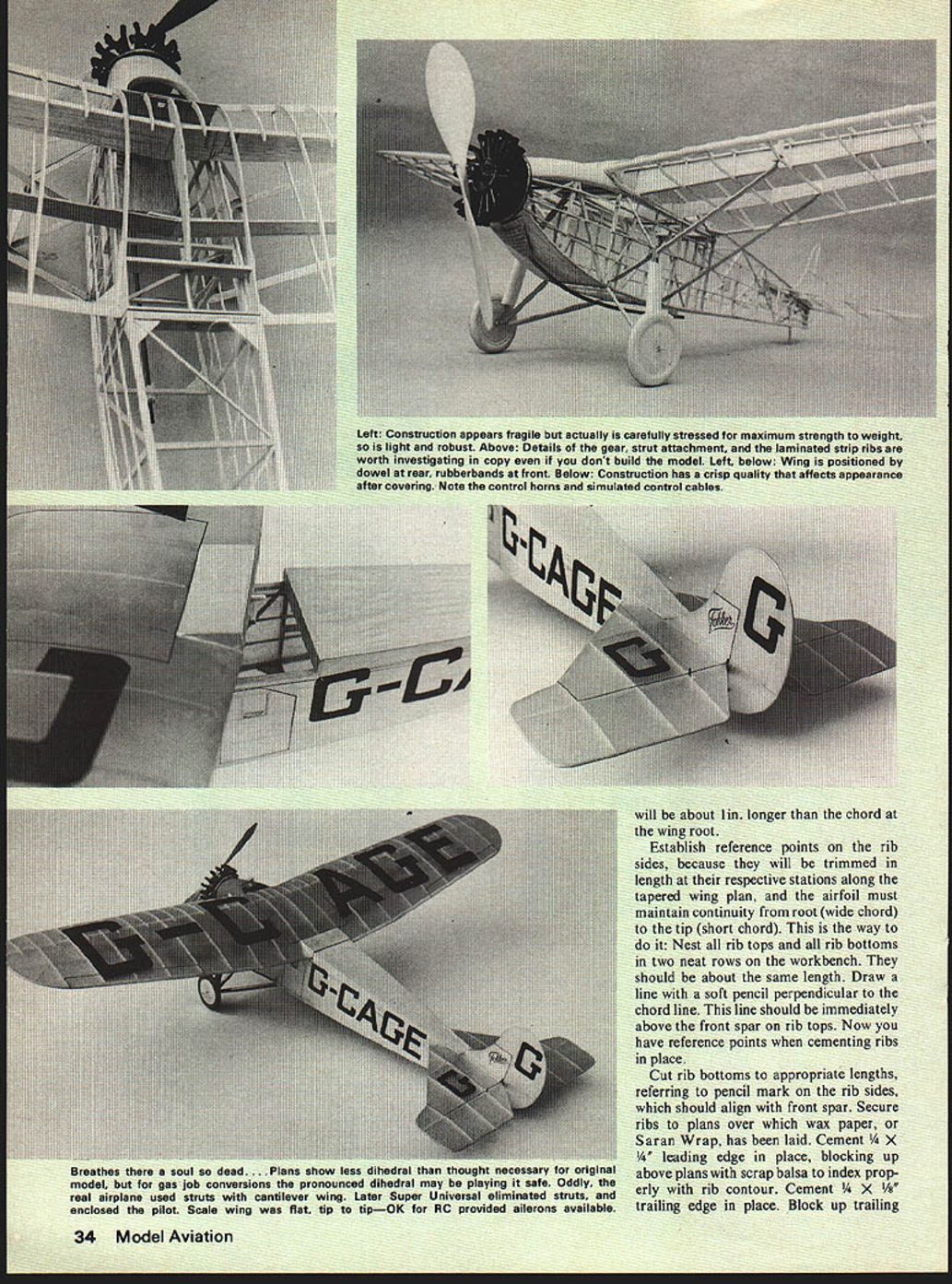
Now, if you are thinking 4 ft. is pretty big for rubber power, let me proselytize on behalf of Jumbo (over 36 in.) rubber scale. The model consistently flies 45 to 50 seconds. It has taken second place in two major scale contests sponsored by the Los Angeles Flightmasters competing against some of the best scale builders anywhere. Add consistent, predictable duration and upper-rank scale points (89 out of a possible 100) at the last Jumbo meet and you have a combination that encourages this type model. Big rubber models are dramatic. Besides being easier to embellish than smaller scale, minor changes incorporated in the plans—such as reduction of dihedral compared with pictures—give a better scale effect. The real aircraft wing is flat when sighted from the front; taper on the underside provides the equivalent slight dihedral.
Construction admonishment seems to apply to successful flying scale rubber models. Build light does not infer flimsy construction. I could name a host of top West Coast scale builders who follow the dictum; their models are wonders of lightweight engineering incorporating attention to stress detail, strategic gusseting, shear panels, etc., to achieve optimum strength.
Wing construction follows fairly conventional practice. Cut front and rear spars from 1/16" hard balsa sheet. Follow the taper shown on the plans. Front spar gets 1/16" x 3/16" caps top and bottom to enhance rigidity. Spar webs with diagonals (the truss effect) were omitted because they seemed to contribute extra weight. If the model is to be powered by an electric or CO2 engine, you would do well to include them. Main ribs should be laminated. Although lamination is more work, it has advantages over ribs cut from sheet in strength and light weight. Both top and bottom rib components are made from 1/16" square basswood and balsa, bent on a cardboard-balsa form at least 1/16" thick. Coat the form edge with paraffin (crayon) to allow easy release in case cement creeps during lay-up.
Make rib components by soaking long pieces of 1/16" square basswood in hot water spiked with about 10% household ammonia for about a half hour. For top ribs use an alternate basswood-balsa-basswood sandwich; bottom ribs are two parts bass and balsa. Wipe parts with a paper towel after soaking and apply white glue sparingly along the two longitudinal edges of the basswood. Apply the 1/16" balsa to the cemented edges to create the lamination. Los Angeles Flightmasters competing against some of the best scale builders anywhere. Add consistent, predictable duration and upper-rank scale points — 89 out of a possible 100 at the last Jumbo meet — and you have a combination that encourages this type of model. Big rubber models are dramatic. Besides being easier to embellish, smaller scale models require only minor changes incorporated in the plans. A reduction of dihedral compared with the pictures gives a better scale effect; the real aircraft’s wing is flat on top when sighted from the front, the taper underside providing an equivalent slight dihedral.
Construction admonishments seem to apply to successful flying scale rubber models. “Build light” does not infer flimsy construction. I could name a host of top West Coast scale builders who, with the exception of ignoring this dictum, achieve wonders. Light‑weight engineering incorporating attention to stress detail, strategic gusseting, shear panels, etc., produces the optimum model.
Universal wing construction follows fairly conventional practice. Cut front and rear spars from 1/16" hard balsa sheet. Follow the taper shown on the plans. Front spar gets 1/16" x 3/16" caps top and bottom to enhance rigidity. Spar webs with diagonals (the truss effect) were omitted because they seemed to contribute extra weight. If the model is to be powered by an electric or CO2 engine, you would do well to include them.
Main ribs should be laminated. Although lamination is more work, it has advantages over ribs cut from sheet in strength and light weight. Both top and bottom rib components are made from 1/16" square basswood and balsa, bent on a cardboard‑balsa form at least 1/16" thick. Coat the form edge with paraffin (crayon) to allow easy release in case cement creeps during lay‑up.
Make rib components by soaking long pieces of 1/16" square basswood in hot water spiked with about 10% household ammonia for about a half hour. For top ribs use an alternate basswood‑balsa‑basswood sandwich; bottom ribs are two parts bass and balsa. Wipe parts with a paper towel after soaking and apply white glue sparingly along the two longitudinal edges of the basswood. Apply the 1/16" balsa to the cemented edges to create the lamination.
- "E" 1/8" SHEET BALSA RUDDER BASE
- 1/8" x 3/16" HARD BALSA POST
- 1/32" x 3/32" BASS LAMIN.
- ADJUSTABLE TRIM TAB
- 1/16" SQ. BALSA LAMINATED
- TISSUE COVERING
- 1/8" SQ. BALSA FUSELAGE FORMERS
- REED SKID
- 1/16" SHEET RIB
- 1/8" x 1/4" BRACES
- 1/16" x 1/4" SPARS TAPERED FROM HARD BALSA
- 1/16" x 1/8" BASS INNER LONGERONS
- 1/16" x 3/16" BALSA OUTER LONGERONS
- 1/16" SQ. HARD BALSA STRINGERS
- 1/16" SQ. BALSA LAMIN. FOR ALL RIB TOPS
- 1/32" BASSWOOD BETWEEN (BASS ON INNER ONLY)
- 1/16" SHEET BALSA SPARS
- 1/8" x 3/8" BALSA TRAILING EDGE (3 PCS)
- 1/16" x 1/8" BRACES
- 1/16" SHEET NOSE RIBS
- 1/32" x 3/32" BASSWOOD LAMINATED TIP BOW
- 1/4" SQ. HARD BALSA L.E.
- 1/16" x 1/4" HARD BALSA SPAR CAPS
- 1/16" SQ. BALSA
- 1/16" SQ. BALSA (label repeated near wheel)
- 1/16" PLYWOOD DISK SANDWICHED BETWEEN
- 1/4" BALSA DISKS SHAPED TO WHEEL-TIRE
- MUFFLER AND L.G. FAIRING WRAPPED WITH INDEX CARD
- ALL L.G. STRUTS: 1/16" SQ. BALSA (or 1/16" x ? hard balsa as shown)
- 1/32" x 3/32" BASSWOOD LAMINATED TIP BOW (repeated)
- 1/4" SQ. HARD BALSA L.E. (repeated)
Angeles Flightmasters, competing against some of the best scale builders anywhere.
Add consistent and predictable duration with upper rank scale points (89 out of a possible 100 at the last Jumbo meet) and you have a combination that encourages this type of model. Big rubber models are dramatic. Besides, they are easier to embellish than smaller scale.
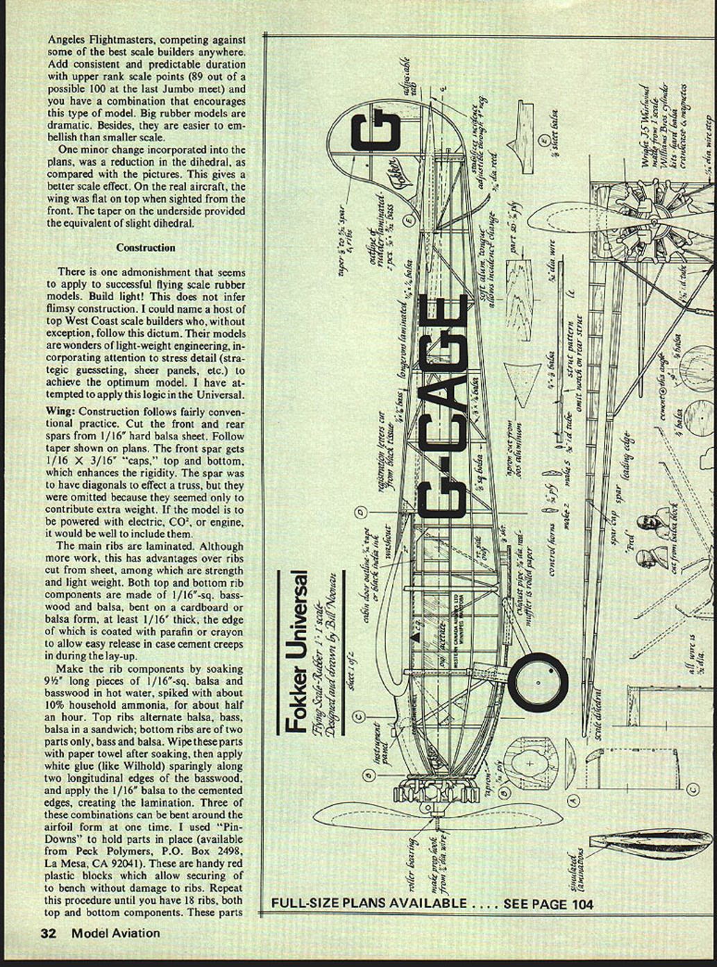
One minor change incorporated into the plans, was a reduction in the dihedral, as compared with the pictures. This gives a better scale effect. On the real aircraft, the wing was flat on top when sighted from the front. The taper on the underside provided the equivalent of slight dihedral.
Construction
There is one admonishment that seems to apply to successful flying scale rubber models. Build light! This does not infer flimsy construction. I could name a host of top West Coast scale builders who, without exception, follow this dictum. Their models are wonders of light-weight engineering, incorporating attention to stress detail (strategic gusseting, shear panels, etc.) to achieve the optimum model. I have attempted to apply this logic in the Universal.
Wing
Construction follows fairly conventional practice. Cut the front and rear spars from 1/16" hard balsa sheet. Follow taper shown on plans. The front spar gets 1/16" x 3/16" "caps," top and bottom, which enhances the rigidity. The spar was to have diagonals to effect a truss, but they were omitted because they seemed only to contribute extra weight. If the model is to be powered with electric, CO2, or engine, it would be well to include them.
The main ribs are laminated. Although more work, this has advantages over ribs cut from sheet, among which are strength and light weight. Both top and bottom rib components are made of 1/16" sq. basswood and balsa, bent on a cardboard or balsa form, at least 1/16" thick, the edge of which is coated with paraffin or crayon to allow easy release in case cement creeps in during the lay-up.
Make the rib components by soaking 9-1/2" long pieces of 1/16" sq. balsa and basswood in hot water, spiked with about 10% household ammonia, for about half an hour. Top ribs alternate balsa, bass, balsa in a sandwich; bottom ribs are of two parts only, bass and balsa. Wipe these parts with paper towel after soaking, then apply white glue (like Wilhold) sparingly along two longitudinal edges of the basswood, and apply the 1/16" balsa to the cemented edges, creating the lamination. Three of these combinations can be bent around the airfoil form at one time. I used "Pin-Downs" to hold parts in place (available from Peck Polymers, P.O. Box 2498, La Mesa, CA 92041). These are handy red plastic blocks which allow securing to bench without damage to ribs. Repeat this procedure until you have 18 ribs, both top and bottom components. These parts
FOKKER UNIVERSAL
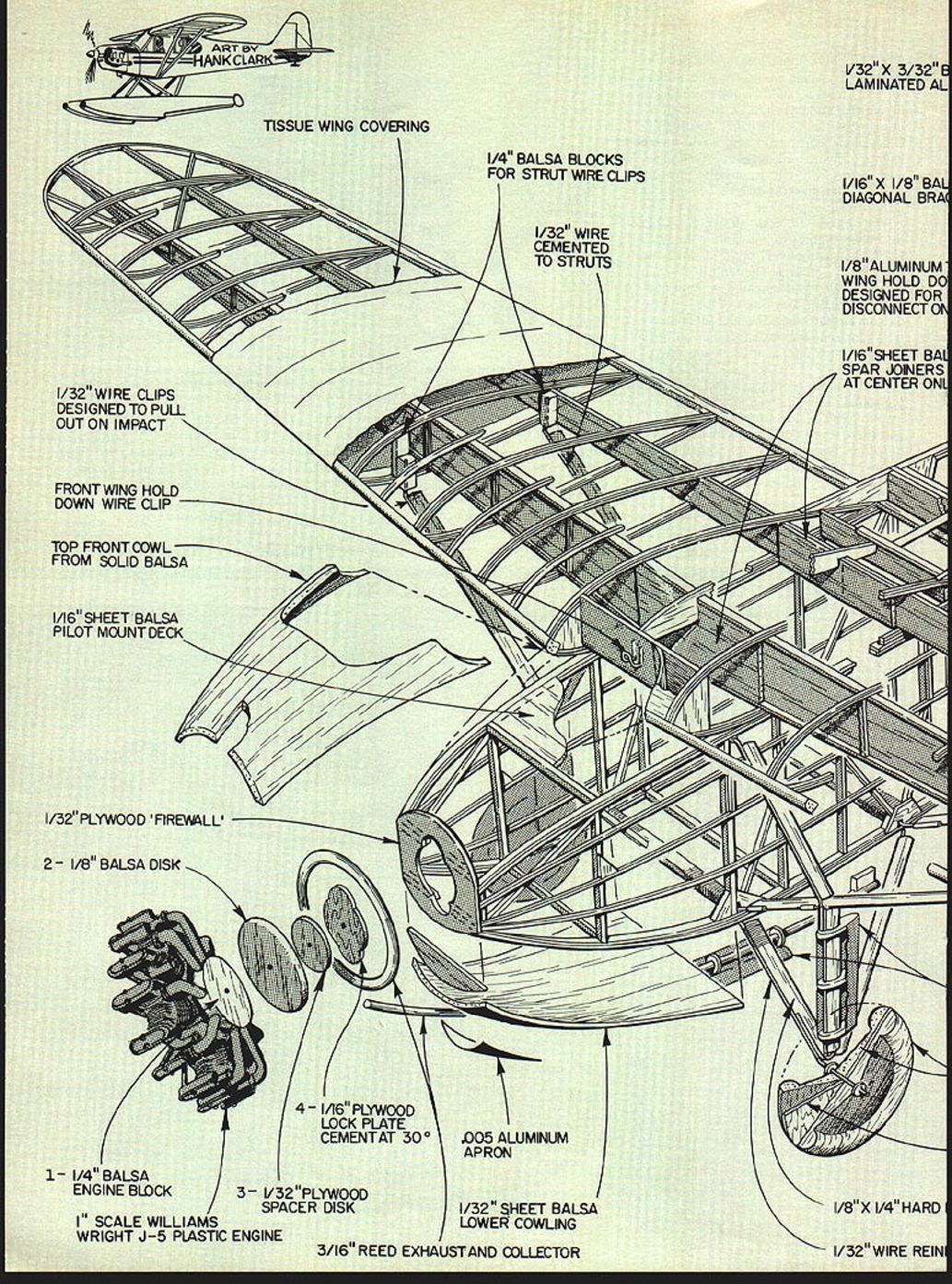
- Laminated Al-tissue wing covering
- 1/4" balsa blocks for strut wire clips
- 1/32" wire cemented to struts (designed to pull out on impact)
- Front wing hold-down wire clip
- Top front cowl from solid balsa, 1/16" sheet
- Pilot mount deck, 1/32" plywood firewall
- 2-1/8" balsa disk
- 1-1/4" balsa engine block
- Scale Williams/Wright J-5 plastic engine
- 3/16" reed exhaust and collector
- 1/32" sheet balsa wheel cowling
- 1/16" x 1/8" balsa diagonal brace
- 1/8" aluminum wing hold-down (designed for disconnect)
- 1/8" x 1/4" hard (spar or member)
- 1/32" wire reinforcement
- 1/16" sheet balsa spar joiners at center
- 4 1/32" plywood spacer disk
- 1/8" square balsa fuselage formers
- 1/8" x 3/16" balsa base
- Balsa post, adjustable
- Tissue covering
- 1/16" sheet ribs
- 1/8" x 1/4" braces
- 1/16" x 1/4" spars tapered from hard balsa
- Muffler and lug fairing wrapped with index card
- 1/4" balsa disks shaped to wheel/tire
- Inner ailerons, 1/16" x 3/16" balsa
- Outer ailerons, 1/16" square hard balsa
- Square balsa stringers
- Laminated balsa for all rib tops (1/32" basswood between 1/16" sheet balsa)
- 1/8" x 3/8" balsa trailing edge (3 pcs)
- 1/16" x 1/8" braces
- 1/16" plywood disk sandwiched between all large struts
- 1/16" square balsa for small struts
- 1/16" x 1/4" hard (member)
- 1/16" sheet nose ribs, balsa
- Spar caps (to be bound under fuselage only), 1/4" square hard balsa
- 1/32" x 3/32" basswood laminated tip bow on inner only
Notes on plan
- FOKKER UNIVERSAL — SCALE 3/8"
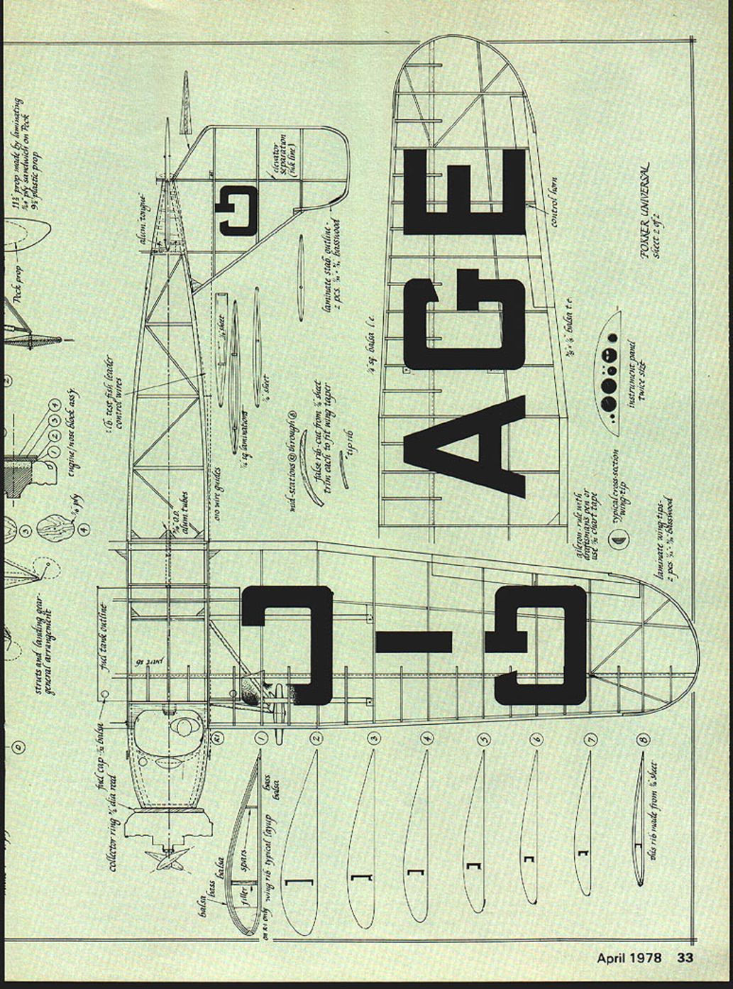
will be about 1in. longer than the chord at the wing root.
Establish reference points on the rib sides, because they will be trimmed in length at their respective stations along the tapered wing plan, and the airfoil must maintain continuity from root (wide chord) to the tip (short chord). This is the way to do it: Nest all rib tops and all rib bottoms in two neat rows on the workbench. They should be about the same length. Draw a line with a soft pencil perpendicular to the chord line. This line should be immediately above the front spar on rib tops. Now you have reference points when cementing ribs in place.
Cut rib bottoms to appropriate lengths, referring to pencil mark on the rib sides, which should align with front spar. Secure ribs to plans over which wax paper, or Saran Wrap, has been laid. Cement 1/4 X 1/4 leading edge in place, blocking up above plans with scrap balsa to index properly with rib contour. Cement 1/4 X 1/8 trailing edge in place. Block up trailing edge at tips to achieve about two degrees wash-out. Cement front spar only in place on top of the ribs, leaving about 1/2 in. surplus length at the airplane center line; later to be trimmed to mate with other wing half and to accommodate proper dihedral.
For fitting top ribs, hold a full-chord rib above spar at penciled reference on the rib; mark the cut-off points at leading and trailing edges for each rib, root rib (R1) to number 8, the tip rib. Note that these ribs do not abut the trailing edge, but cement on top of the bottom rib. (See detail on plans.) Cement each rib in place. Each should contact the leading edge, spar, and bottom rib at the trailing edge.
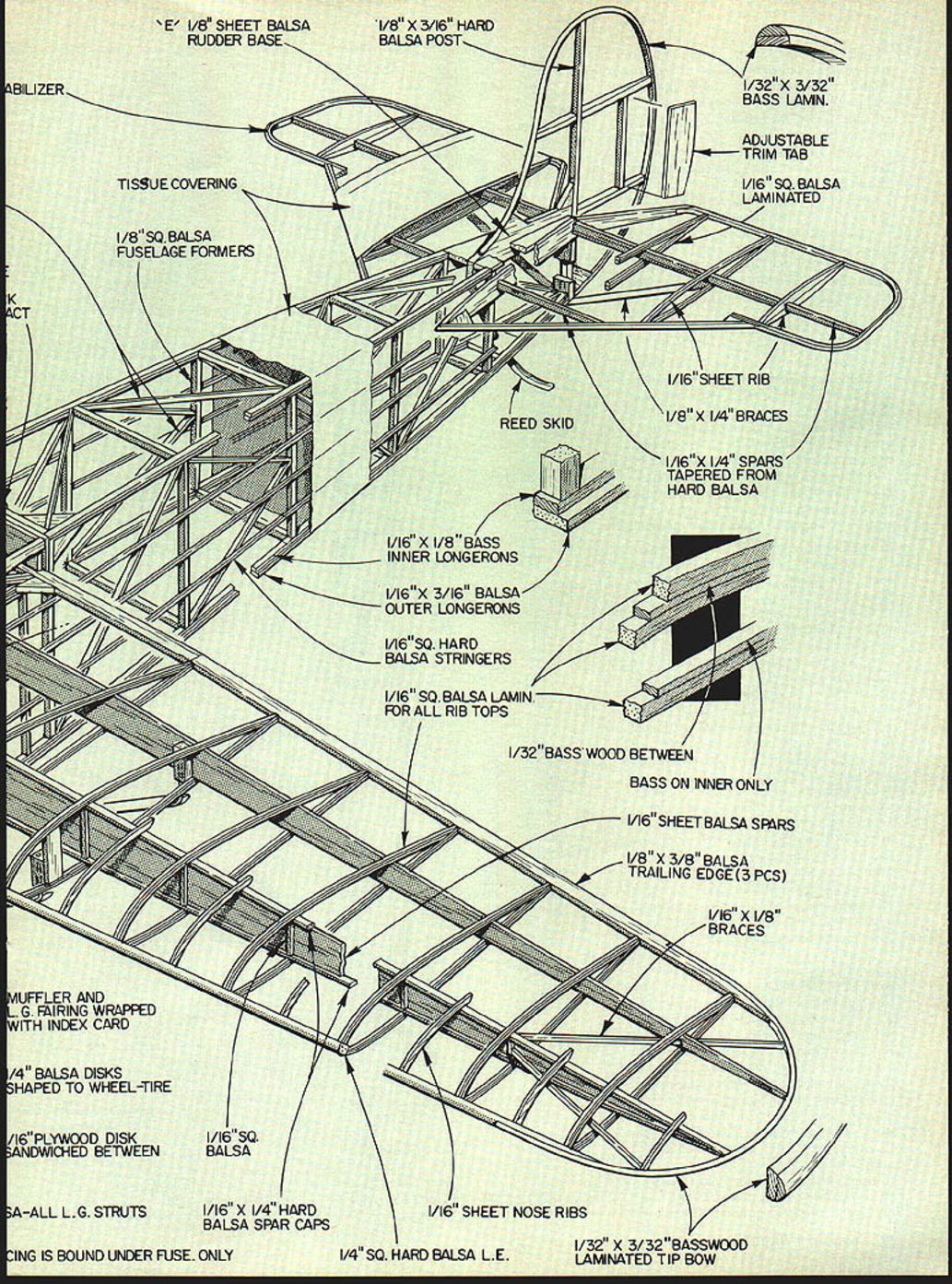
The wing tips are laminated from 1/8 X 1/32" basswood, soaked, and bent around a wing-tip form, in the same manner as the ribs. This gives you a 1/16-in.-thick tip, when viewed from above. Notch leading and trailing edges to receive the tips after they are dry.
Slide the rear spar into position, starting at the root rib, until it comes into contact with the tip, and cement it in place. Note break at rib number 2. Cement the two parts carefully. This spar is a little longer than necessary, allow for joining with other half wing.
Add diagonals at wing tip as shown. Cut 1/32" plywood dihedral spar brace (part SB). When both wing panels are complete, trim spar surplus so both spars mate with precision. Apply a coat of cement on the end grain of the spars and allow to dry. This will provide a superior bond when final assembly is made.
Apply cement to spar brace and position on front of front spar. Join the two panels, using clothes pins or spring clips (stationery supply stores) to hold the brace tightly while cement dries. Cut similar brace for rear spar and follow same procedure. Fill in trailing edge between panels with hard 1/4 X 1/4" balsa. This is a stress point if the wing is subjected to a hard blow. The center-section leading edge is made of a soft balsa block which bridges the root ribs. The "cove," a continuation of the cockpit, is cut after the fuselage is complete.
Install 1/16" sheet balsa false ribs in place midway between main ribs, cementing them to leading edge and top of front spar. Cement center-line rib in place. Don't forget the gussets at critical points at the trailing edge.
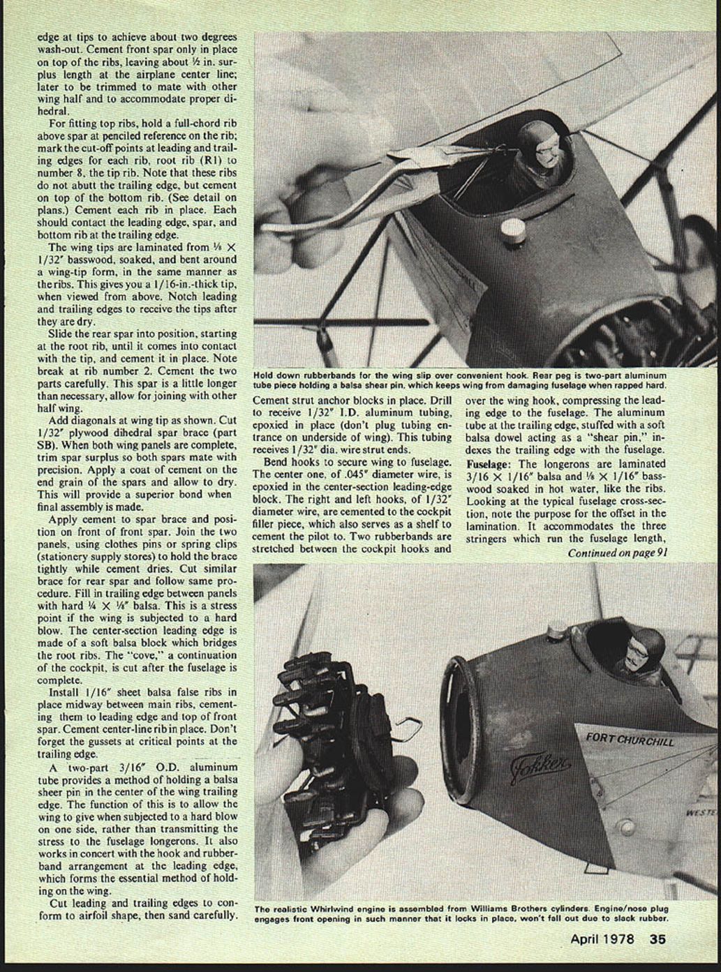
A two-part 3/16" O.D. aluminum tube provides a method of holding a balsa shear pin in the center of the wing trailing edge. The function of this is to allow the wing to give when subjected to a hard blow on one side, rather than transmitting the stress to the fuselage longerons. It also works in concert with the hook and rubberband arrangement at the leading edge, which forms the essential method of holding on the wing.
Cut leading and trailing edges to conform to airfoil shape, then sand carefully.
Cement strut anchor blocks in place. Drill to receive 1/32" I.D. aluminum tubing, epoxied in place (don't plug tubing entrance on underside of wing). This tubing receives 1/32" dia. wire strut ends.
Bend hooks to secure wing to fuselage. The center one, of .045" diameter wire, is epoxied in the center-section leading-edge block. The right and left hooks, of 1/32" diameter wire, are cemented to the cockpit filler piece, which also serves as a shelf to cement the pilot to. Two rubberbands are stretched between the cockpit hooks and over the wing hook, compressing the leading edge to the fuselage. The aluminum tube at the trailing edge, stuffed with a soft balsa dowel acting as a "shear pin," indexes the trailing edge with the fuselage.
Fuselage: The longerons are laminated 3/16 X 1/16" balsa and 1/8 X 1/16" basswood soaked in hot water, like the ribs. Looking at the typical fuselage cross-section, note the purpose for the offset in the lamination. It accommodates the three stringers which run the fuselage length,
Fokker Universal
and whose bearing surfaces are on the same plane as the longeron edges—just as it was on the real aircraft.
The vertical components are 1/8"-sq. medium balsa, with the exception of the two which form window separations, which are 1/8" x 1/16", as are all diagonal members.
Lay the laminated longerons over wax-paper protected plans, then cement in verticals and diagonals. Repeat the process for the second side, keeping in mind the lamination arrangement of the longerons, which have a right and a left orientation to allow for the stringers. After the glue is dry, remove from the plans, and separate them. Add stringers after sides are joined. Back up stringers with 1/8" x 1/16" balsa doublers where they form top and bottom window frames.
Cut triangle-shaped gussets from 1/16" plywood for the high-stress points where landing gear and strut wire ends contact the fuselage. These are cemented to the inside faces of the fuselage prior to joining the sides so they are sandwiched between formers. longerons and the verticals, flush with fuselage sides. Drill 1/32" diameter holes for strut anchor wire to protrude from.
Join the sides, starting at the tail post, holding it together with a clothespin while drying. Next, put in 1/8" sq. cross pieces at the widest part of the fuselage, under the wing. Be sure fuselage is square. Add balsa gussets as shown; these points are subjected to considerable stress later when bending longerons together at the nose. Add the hard 1/16" sheet balsa plate immediately behind the wing center section (the one the 3/16" diameter tubing goes through). This is important too, as the top longerons do funny things when you pinch the nose, which is next.
Cut the cross pieces which bridge the fuselage sides right behind the plywood nose bulkhead (B), apply cement, and carefully bring the sides together to compress the parts. Allow to dry overnight. For good measure, cement temporary scraps across the longerons, removing after all cross pieces are in. Cut the cockpit block from soft balsa, hollow to about 1/8 in. thick wall, and cement to top longerons. Cut former (A) and cement in place under nose. Cover portion from this former to the cross piece, that the front landing gear wire secures to, with 1/32" sheet balsa, grain running with the fuselage. Add the hard 1/8"-thick balsa squares at point shown to form support for aluminum tube rubber anchor. Add any missing gussets.
The 1/32" plywood nose bulkhead has a distinctively shaped hole to act as a retainer for the nose block (dummy Whirlwind), which has a mating piece (4) cemented to its back. Rotate the mating piece and engine about 30 degrees after insertion, to bring the engine into correct position. This constitutes a lock, preventing the nose block/engine/prop from falling out after rubber tension ceases when rubber unwinds.
Williams Bros. make the Wright Whirlwind easy with their 1" scale plastic cylinders, available individually, each with crankcase diagram. The case is cut from hard balsa, and becomes the nose block. Finish the crankcase with three coats of sanding sealer. I achieved a very satisfactory "worn" look by spraying the part with silver enamel, and following with flat black (lightly) while the silver was still wet. The same procedure was followed on the exhaust collector ring and long pipe. Assemble nine cylinders, epoxy in place, add ignition harness (made from 1/16" O.D. aluminum tube), and magnetos. Drill hole through the crankcase and associated back pieces to accept 1/16" I.D. brass tubing, which acts as bushing for prop hook. Provide about two degrees downthrust when drilling. No side compensation is made.
Bend the collector ring from reed (about 3/16" diameter). Soak the reed in water overnight, and find a suitable can or bottle to act as a form during drying. I obtained the reed from a display store where it sold as handles for children's balloons. The main exhaust pipe is the same stuff, with a paper tube muffler. Note the aluminum "apron" that covers the place where the collector ring and exhaust join. This had the brushed swirls patterning indigenous to some planes of this vintage. These were achieved with an electric draftsman's eraser.
Propeller
The prop is made by extending a 9-1/4 in. Peck Polymer plastic prop (PPpp) to 11-1/4 in. diameter. Cut four pieces (see pattern) of 1/64" plywood, and epoxy in place on the plastic prop, using plenty of clothespins during cure. The right pitch merely extends to tips, and has proved satisfactory. Sand edges to achieve appropriate airfoil. Our prop simulated the laminations found on some Universal props, with mahogany stain alternating with the natural plywood. Apply two coats of clear nitrate dope for finish. Although Peck prop incorporates a free-wheeling notch, I drilled out the prop to receive a brass 1/16" I.D. insert, and notched this in a similar manner for the free-wheeling device.
Landing Gear
Bend landing gear, and strut fastening parts, from 1/32" diameter wire. Bind landing gear to fuselage cross pieces, and follow with epoxy cement. Epoxy 3/32" x 1/4" streamline balsa fairings to complete the struts.
Wheels were turned from two pieces of hard 1/4" sheet balsa, set at right angles to each other, sandwiching a piece of 1/16" plywood in the middle as a core. Here's how: Cut wheel diameter about 1/8 in. oversize, make up the balsa and ply sandwich. Drill 1/4"-diameter hole in center hub. Epoxy 1-1/2 in. length of 1/4"-diameter birch dowel in the hole. You should have what looks like a bad attempt at a balsa umbrella, flattened out. Secure the dowel in the chuck of your handy drill motor (a drill stand facilitates things) then turn the wheel, contouring it using progressively finer grades of garnet paper. It's a poor man's lathe. Cut off dowel flush with hub after turning. Drill hole in center of dowel to accept 1/32" I.D. brass bushing. Finish. with three coats of sanding sealer. Spray it silver. Tires are finished in flat, dark gray.
Struts:
The main struts are constructed from 1/4 x 1/8" hard balsa, cut and sanded to streamline shape. The strut bottom ends are notched at the leading edge to accept 1/2-in. length, 1/32" I.D. aluminum tubing, which mates with the wire protruding from fuselage sides at bottom longeron. Top ends reverse the tube and wire combination. About one third the way up the front strut, a notch is cut to receive 1/2-in. length of tubing, which in turn, will receive 1/32" diameter wire from vertical (oleo) landing gear strut. This strut has the wire running the full length of the leading edge. It solders to the other landing gear components at the axle. Note that the oleo cover is a broad chord sheath made from stiff paper formed on streamline formers. A short jury strut runs from the top of the oleo strut to plug into a tube in the fuselage.
To simulate gray anodized metal, we wrapped the struts with 3M Scotchcal Mylar foil, a chrome-like film about 1-mil thick, with an adhesive backing. It is available from sign shop suppliers. This, in turn, was covered with translucent gray Zip-A-Tone, an artist's color aid. It comes in adhesive backed sheets in a considerable range of colors and shades of gray. It provides a finish which cannot be simulated with paint, and makes the struts almost indestructible.
The short stabilizer support struts are cut from bamboo and finished color similar to main struts. Cement them in place, after a few test flights which allow stabilizer incidence to be set.
Tail Surfaces:
Bend the outlines of both fin and stabilizer from 3/32 x 1/32" two-ply basswood laminations. Follow soaking process as described for ribs, bending the outlines around a cardboard or balsa form. I am a firm believer in the benefits of laminating where it is appropriate, and an advocate of balsa and basswood combination on a model of this size.
Laminate stabilizer ribs (tops and bottoms) from two pieces of 1/16"-sq. balsa, to form a streamline section. Basswood is avoided here to avoid adding weight at the tail. Cut the stabilizer spars from 1/4 x 3/32" hard balsa, and taper them toward the tips. When the rib bottoms are dry, position them over the spars, then cement the full-span spar in place, followed by the short one. Cement right and left laminated outlines to the ribs and spars, followed by rib tops. Add the 1/16" sheet ribs, which run parallel to fuselage sides. These are bridged with 1/32" sheet balsa, grain running parallel with the spar, to form a continuation of the fuselage profile at the tail.
Provision is made for changing incidence by securing the stabilizer to the fuselage at the front stabilizer spar. This is done with a soft aluminum tongue (aluminum beer can works fine), which epoxies to cross piece in fuselage. The stabilizer sits on the notch at the extreme end of the fuselage just ahead of the rudder post.
On our model the stabilizer sat at 0 degrees, but provision was made for up to about 4 degrees negative incidence, by providing a notch in the vertical fin just ahead of its spar. This allows passage of the stabilizer spar in an upward arc (through the 4 degrees) until the correct adjustment is reached. We were sure no positive incidence would be needed. During test flights, the spar was pinned temporarily, cemented later. The 1/32" balsa that covers the stabilizer center section is cut on the center line to form a 1/8-in. slot which accepts the fin; the fin is cemented to the fuselage.
Since the fin is almost flat in section, build it over the plans, using 1/8" sq. balsa for spar and other parts, except outline, which is laminated like the stab. Add rudder tab of soft 1/8" sheet, as shown. Don't forget the gussets.
Covering and Finish:
The fuselage is covered with white Japanese tissue, lightly sprayed with water for shrinking, and then given three coats of clear nitrate dope diluted to a 50/50 solution. Add plasticizer to minimize warps, particularly on wing, stabilizer, and rudder. Apply the finish coat on the fuselage with an airbrush. Into the clear dope we mixed "brill", a silver powder utilized by commercial painters to achieve simulated metallic effects. This gave an authentic and distinctive finish, but maintains the translucent quality of the tissue, the hallmark of most rubber models. The only concession in the use of opaque paint was the accent green trim on the nose. It was Testor's Pla flat green, masked and sprayed over balsa prepared with three coats of sanding sealer.
Cover the wing and stabilizer with chrome yellow Japanese tissue, grain running parallel with the spar. Follow the same procedure as the fuselage, omitting the silver, of course. The little wedge-shaped area at the wing center section trailing edge is silver like the fuselage. The vertical fin is silver.
Cut registration letters from black tissue. Apply them with clear dope after the third coat of clear dope. Wing letters and the prefix "G", which appears on the stabilizer, are repeated on the underside surfaces.
The legend under the cabin windows WESTERN CANADA AIRWAYS, LTD., and FORT CHURCHILL under the cockpit, are 14-point News Gothic rub-on type, available at better art supply stores. The Fokker script logo which appears on the fin and nose is made by hand-lettering the original Fokker style (from photographic reference), and photographing it to size. This, in turn, is converted to rub-off transfer by using I.N.T., a new 3M product available at graphic arts supply houses.
The tail skid is made from the same reed as the exhaust system. It is slightly tapered, cemented in place, painted dark brown.
Control horns, between which is stretched 2-lb. fishing leader which has been sprayed black, are made from 1/32" sheet plywood. Surface horns are painted dark gray. The movable surfaces, like the ailerons, elevator and rudder, are delineated with 1/32" chart tape, or ruled with black India ink. The same applies to cabin door and fuel tank outlines on top surface of wing.
Make individual cabin windows and windshield from .010 clear acetate, secured with Hot-Stuff, or equivalent. Paint the window sills and vertical separations light gray. The cockpit, including the wing notch, is painted flat dark gray.
The oil filler cap in front of the cockpit, and the fuel filler cap below the cockpit on the left side of the fuselage, were made from discarded marking pen caps, cut to proper length. Cockpit coaming was made from leather thong, cemented in place with, yes, Hot-Stuff. The pilot was carved from balsa, given three coats of sanding sealer. Acrylic artists colors, available in tubes, were used to apply the cosmetic touches. Moustache is optional. Goggles are bent from fine brass wire, dipped in clear dope to make microfilm lenses.
Flying: Check C.G. before testing with 14 strands of lubricated 3/16" Sig Contest rubber. When limp the rubber is about 28 in. long, it hangs out the nose about 9 in. Break in the rubber carefully, using your method. I suggest about 350-400 turns for tests, enough to provide sufficient power to observe balance and turn characteristics.
Maximum turns we have tried is about 900. With this, the model R.O.G.'s realistically and flies in large circles. It is extremely stable, and never causes apprehension.
The Fokker Universal is a very satisfying model, one of my favorites. Whether you build to compete, or just for pleasure, it has plenty to offer.
Transcribed from original scans by AI. Minor OCR errors may remain.

