

Fore-and-Aft CG: How To Find It
Dick Eimert
Introduction
Weight-and-balance measurements on a full-scale aircraft are required after manufacture and periodically thereafter, depending on use and when major repairs or modifications are completed. The resultant empty weight center of gravity (ECG) becomes the starting point for the pilot to properly load the aircraft with fuel, passengers, and cargo and remain within the center-of-gravity limits dictated by the designer. This article concerns the fore-and-aft CG.
With the trend toward larger models, actual weight-and-balance measurements can be accomplished using the same procedures and formulas as those used on full-scale aircraft. The procedure requires at least one good scale (with weight capability of at least one-half the weight of the aircraft), a sensitive bubble (spirit) level, a steel scale, and a carpenter's square.
Terms and concepts
- Datum: An arbitrary fixed point from which all longitudinal measurements are made. Early aircraft used the firewall or the leading edge of the wing as the datum, but this can introduce errors. It is common to choose a point forward of the aircraft so that all arms are positive.
- Arm: The distance from the datum to a weight or jack point. The arm multiplied by the weight at that distance gives the moment.
- Moment: Weight × arm.
- Jack points: On full-scale aircraft these are hard points for a hydraulic jack; on a model they are typically the main wheel centers and tail wheel/skid center.
- Weight: The scale reading observed minus any non-aircraft weight (tare), such as support blocks or chocks.
- ECG (Empty Center of Gravity): The resultant arm aft of the datum that shows the fore-and-aft CG of the model.
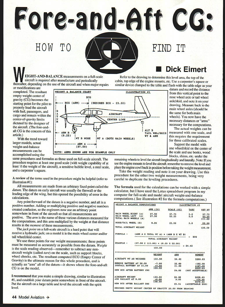
Refer to the illustrations (illustration #1 and #2) for diagrammatic help and example computations.
Preparing the aircraft and datum
- Make a simple drawing of the aircraft side view and establish your datum somewhere in front of the aircraft.
- Put the aircraft on a large table and level it longitudinally and laterally with a spirit level.
- Using a carpenter's square or similar device clamped to the table and flush with the table edge, mark the vertical datum point on your drawing.
- Measure and record the distance from the datum to:
- Nose wheel axle or tail wheel axle/skid,
- Main wheel axles (measure both; they should be the same).
These distances are the arms needed for the computations.
Measuring weights
You can perform the measurements with a single scale; three calibrated scales are not required.
- Support the model with one wheel or skid on the center of the scale.
- Use books, wood blocks, shims, etc., under the remaining wheels to level the aircraft longitudinally and laterally (duplicate this leveling for each reading).
- Note: If you use the engine mounts to level the aircraft, remove the level and replace the engine cowl before taking the weight measurement.
- Take the weight reading, subtract any tare, and note the reading and its arm on your drawing.
- Repeat for the other two weight/jack points, taking care to duplicate leveling each time.
Calculations
- The moment for each measurement = weight × arm.
- Sum the moments to get the total moment. Sum the weights to get the total empty weight.
- ECG (arm) = total moment ÷ total weight.
A simple calculator is adequate for these computations; spreadsheet programs (e.g., Lotus, Excel) make the process and adjustments easier. Illustration #2 shows example formula computations with fictitious numbers—substitute your own readings.
Setting the desired ECG and adding ballast
- The desired ECG is usually noted on the model drawings; you can often use the full-scale aircraft data. Measure the distance from this desired point to the datum and record it.
- To shift the ECG, add ballast or reposition equipment (preferable). To compute the effect of added ballast:
- Ballast moment = ballast weight × ballast arm.
- New total moment = as-weighed moment + ballast moment.
- New total weight = as-weighed weight + ballast weight.
- New ECG = new total moment ÷ new total weight.
A computerized chart lets you see the resultant ECG as you add or move weight. It is preferable to relocate required equipment (for example, a battery) rather than add dead ballast.
Fuel and other variable loads
- You can compute ECG changes for fuel or any variable cargo by measuring from the datum to the center of the tank and multiplying by the fuel weight to get the fuel moment. Insert this into your calculations to see the resultant ECG shift.
- On full-scale aircraft, fuel tanks are often placed on or near the CG so fuel burn has little effect on balance. On many models, tanks are forward of the ECG; therefore, weight-and-balance measurements should be conducted with the tank empty. Adding fuel will shift the ECG forward (nose down), which is acceptable. The ECG should never be allowed to shift aft of the desired position.
Conclusion
The procedure is straightforward, and a model's fore-and-aft center of gravity can be found with greater accuracy than many other methods. Use careful measurements, accurate leveling, and correct computations to ensure safe loading.
Reviewer's note
For any model the "flying" CG location is what matters—too far forward or aft has bad consequences. A reliable plan will specify this; otherwise (or for a new design) it must be determined by formula or flight tests. See "Making Scale Model Airplanes Fly," available from Aircraft Data, Box 703576, Dallas TX 75370-3576. Include a self-addressed stamped envelope (SASE) for info.
Dick Eimert 8 Overbrook Dr. Monsey, NY 10952
Transcribed from original scans by AI. Minor OCR errors may remain.

