
Four Bits
Designed by Dave Jackson
Text by Bill Cranston
ONE OF THE most popular and fastest growing competitive events to make the RC scene in a long time is Quickie 500 racing. Basically, Quickie 500 is the racing of a 500 sq. in., .40-sized front-rotor engine aircraft. The objective of Quickie 500 racing is "To provide closed course racing that will encourage participation by the sport and novice racing enthusiast at the lowest cost."
Racing of aircraft is a lot of fun — fun to be shared by the average RC'er. Racing need not require specialized or hard to build and fly aircraft. Racing of aircraft will be fun, if an event such as the Quickie 500, provides the average RC'er an opportunity to:
- Race a simple, easy to build aircraft.
- Fly a stable, docile aircraft that can be sport flown as well as raced.
- Be competitive with a stock, out-of-the-box, .40 FR mill.
- Not be required to virtually carve-your-own props, mix-your-own blend of secret fuel, or any other specialized techniques the Formula One boys use.
- Race with some assurance you've got just as good a chance to win as the next RC'er.
There are perhaps three or four different aircraft currently being flown in the Quickie 500 racing event. All of these aircraft are of similar design. The "4 BITS" is a departure from these designs.
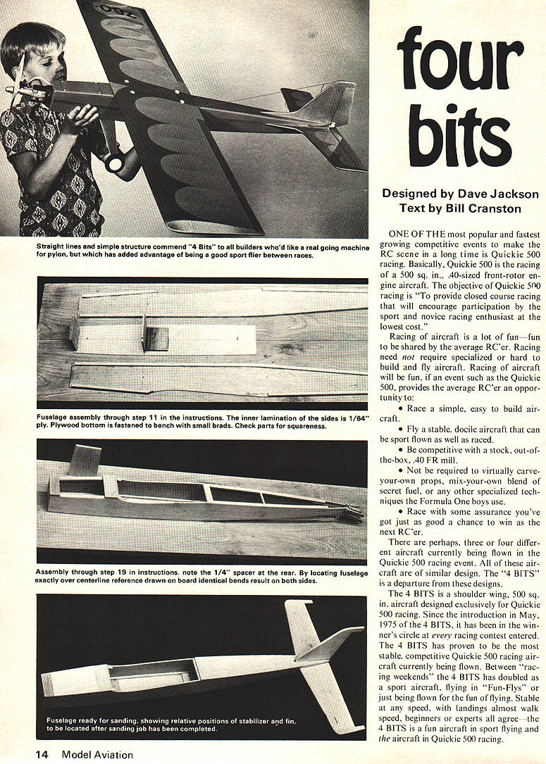
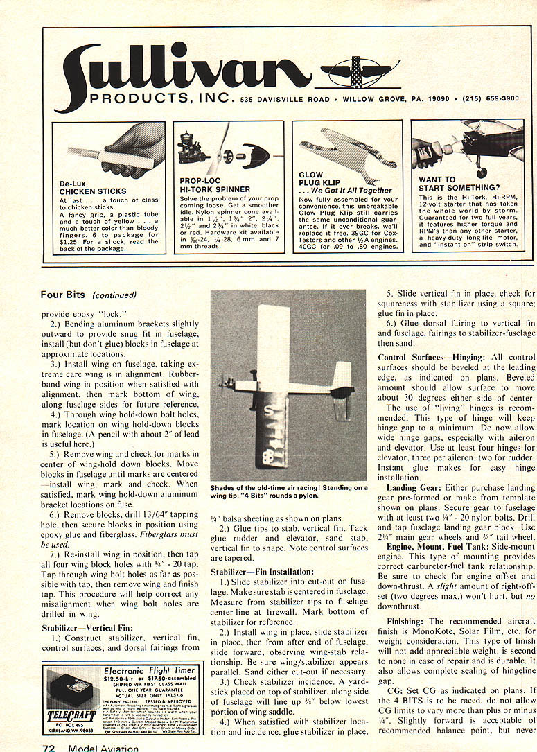
The 4 BITS is a shoulder wing, 500 sq. in. aircraft designed exclusively for Quickie 500 racing. Since the introduction in May, 1975 of the 4 BITS, it has been in the winners' circle at every racing contest entered. The 4 BITS has proven to be the most stable, competitive Quickie 500 racing aircraft currently being flown. Between "racing weekends" the 4 BITS has doubled as a sport aircraft, flying in "Fun-Flys" or just being flown for the fun of flying. Stable at any speed, with landings almost walk speed, beginners or experts all agree — the 4 BITS is a fun aircraft in sport flying and the aircraft in Quickie 500 racing.
Specifications
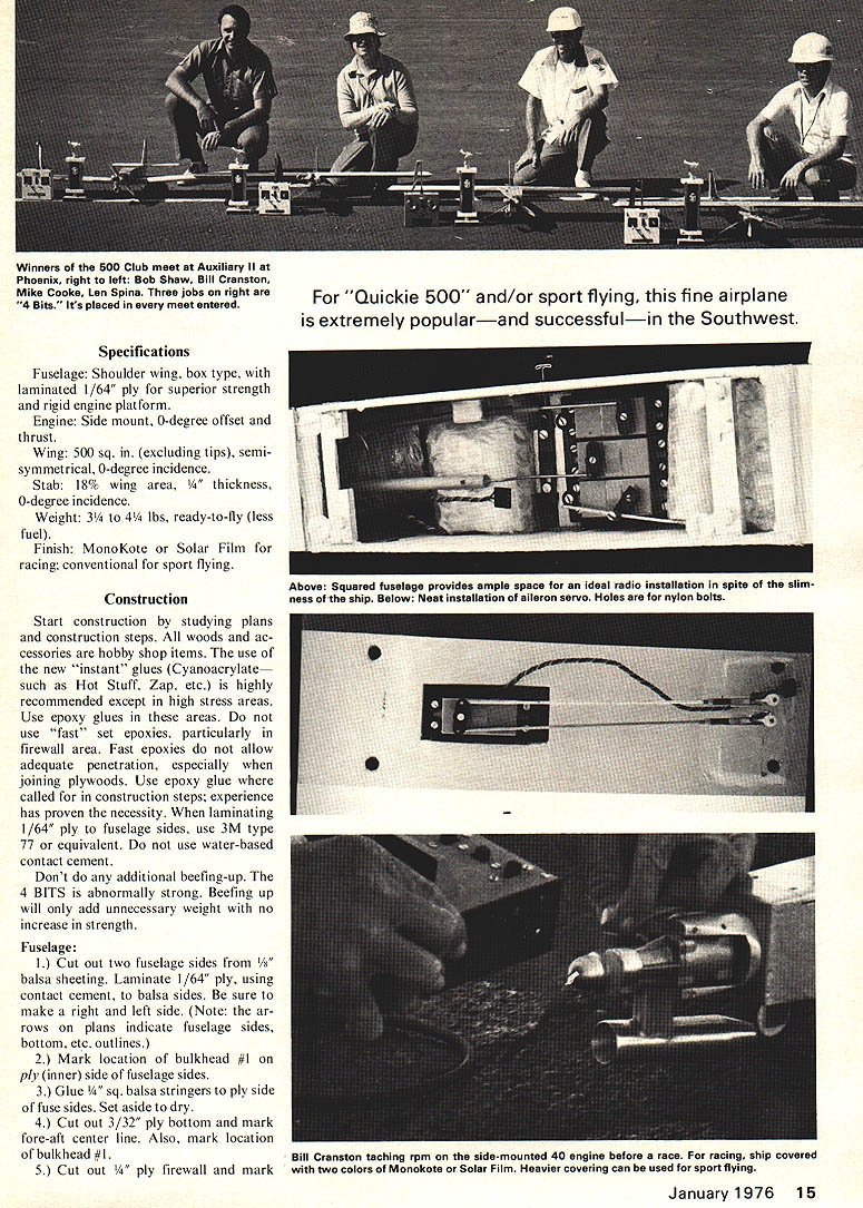
Fuselage: Shoulder wing, box type, with laminated 1/64" ply for superior strength and rigid engine platform.
Engine: Side mount, 0-degree offset and thrust.
Wing: 500 sq. in. (excluding tips), semisymmetrical, 0-degree incidence.
Stab: 18% wing area, 1/4" thickness, 0-degree incidence.
Weight: 3 3/4 to 4 1/4 lbs, ready-to-fly (less fuel).
Finish: MonoKote or Solar Film for racing; conventional for sport flying.
Construction
Start construction by studying plans and construction steps. All woods and accessories are hobby shop items. The use of the new "instant" glues (Cyanoacrylates such as Hot Stuff, Zap, etc.) is highly recommended except in high stress areas. Use epoxy glues in these areas. Do not use "fast" set epoxies, particularly in firewall area. Fast epoxies do not allow adequate penetration, especially when joining plywoods. Use epoxy glue where called for in construction steps; experience has proven the necessity. When laminating 1/64" ply to fuselage sides, use 3M type 77 or equivalent. Do not use water-based contact cement.
Don't do any additional beefing-up. The 4 BITS is abnormally strong. Beefing up will only add unnecessary weight with no increase in strength.
Fuselage
1.) Cut out two fuselage sides from 1/8" balsa sheeting. Laminate 1/64" ply, using contact cement, to balsa sides. Be sure to make a right and left side. (Note: the arrows on plans indicate fuselage sides, bottom, etc. outlines.)
2.) Mark location of bulkhead #1 on ply (inner) side of fuselage sides.
3.) Glue 1/4" sq. balsa stringers to ply side of fuse sides. Set aside to dry.
4.) Cut out 3/32" ply bottom and mark fore-aft center line. Also, mark location of bulkhead #1.
5.) Cut out 1/4" ply firewall and mark
Four Bits
center line both vertically and horizontally.
6.) Draw at least a 36" straight reference line on work surface.
7.) Lay bottom 3/32" ply over this reference line, aligning center line of ply bottom with work surface reference line. Using small brads, nail ply bottom to work surface. (Leave enough of brad exposed for easy removal later.)
8.) Cut out 1/8" balsa #1 bulkhead. Be sure balsa grain is vertical when glued to ply bottom. Glue #1 bulkhead in place on ply bottom, making sure bulkhead is square with bottom.
9.) Cut out two 1/4" x 3/4" balsa wing-saddle fuselage spacers. Glue lower spacer to ply bottom, noting location on plans. (Note: the 4 BITS does not use a bulkhead at this location.) 10.) Epoxy glue firewall to ply bottom. The firewall is flush with front edge of ply bottom. Using a square, be absolutely certain firewall is true with center line on bottom ply and is true vertically.
11.) Cut out 1/4" x 2" ply landing gear block. Epoxy glue to bottom, butting up to #1 bulkhead.
12.) After both firewall and landing gear block epoxy has set, glue fuse sides to ply bottom. Use epoxy glue at firewall and #1 bulkhead. Be sure 1/4" sq. balsa fuselage stringers are "snug" against ply bottom. Use clamps at firewall and #1 bulkhead locations.
13.) Glue upper wing-saddle fuselage spacer in location. This spacer will help keep fuselage sides true at top.
14.) After fuselage assembly epoxy has set, pull in rear fuselage sides, using scrap 1/4" balsa as spacer at rear. Be sure fuselage sides are centered over work surface reference line. (Note: Scrap 1/4" balsa should be "tack" glued in place at vertical fin location.)
15.) Glue in upper and lower 1/4" sq. balsa rear fuselage spacers at locations indicated on plans. Do not omit these spacers.
16.) Cut out 1/4" x 1" ply or pine front top block, then epoxy glue block to fuselage and firewall.
17.) Cut out hatch from 1/4" hard balsa. Length is 4-1/4" and approximately 3-3/4" wide. Length is important.
18.) Cut out rear 1/4" x 1-9/16" hard balsa top block. Balsa grain should be crossways to fuselage. Sand rear edge of top block to approximately 45 degrees to match wing saddle contour.
19.) Using hatch as spacer, epoxy glue rear top block to #1 bulkhead and fuselage sides. Do not glue in hatch.
20.) Cut out 1/8" balsa fuselage rear top sheeting and glue to fuse.
21.) Allowing ample time for fuselage assembly to dry, remove hatch, pull brads and remove assembly from work surface.
22.) Invert fuselage, glue tail wheel ply bracket support at rear of fuselage, then glue 1/8" balsa bottom sheeting to fuse.
23.) Cut out two 1/4" x 3/4" spruce hatch hold-down blocks. Fit and epoxy glue in fuselage at locations shown on plans.
24.) Drill four 3/32" holes in hatch at locations shown on plans, then "plug" holes with 1/4" dowels. Sand flush. Use epoxy glue for dowel plugs.
25.) Tack glue hatch to fuselage.
26.) Sand entire fuselage, rounding corners to no greater than 1/4". Do not remove scrap 1/4" balsa at rear of fuselage until fuselage has been sanded.
27.) Remove hatch, epoxy glue 1/4" sq. balsa corner bracing at top and bottom of firewall.
Wing:
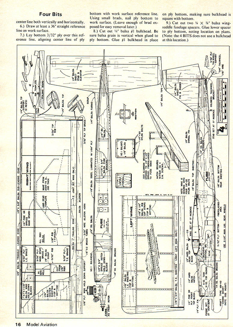
1.) Make a rib template from 1/16" ply. Note rib is semi-symmetrical. Mark bottom of ribs as ribs are cut out. Make 16 1/16" ribs and 4 3/32" ribs.
2.) Cut and tape left wing plan to right wing plan and tape plans to building surface. The wing is built in one piece only.
3.) Using 1/16" x 1/4" hard balsa or pine, make two 25" shims. Align rear of shims with rear of spar as indicated on plans and tape shims down.
4.) Make main spars from 1/4" sq. spruce or pine. Do not substitute balsa for main spars. Tape top and bottom 1/4" sq. spar to shim, noting rear of spar aligns with rear of shim.
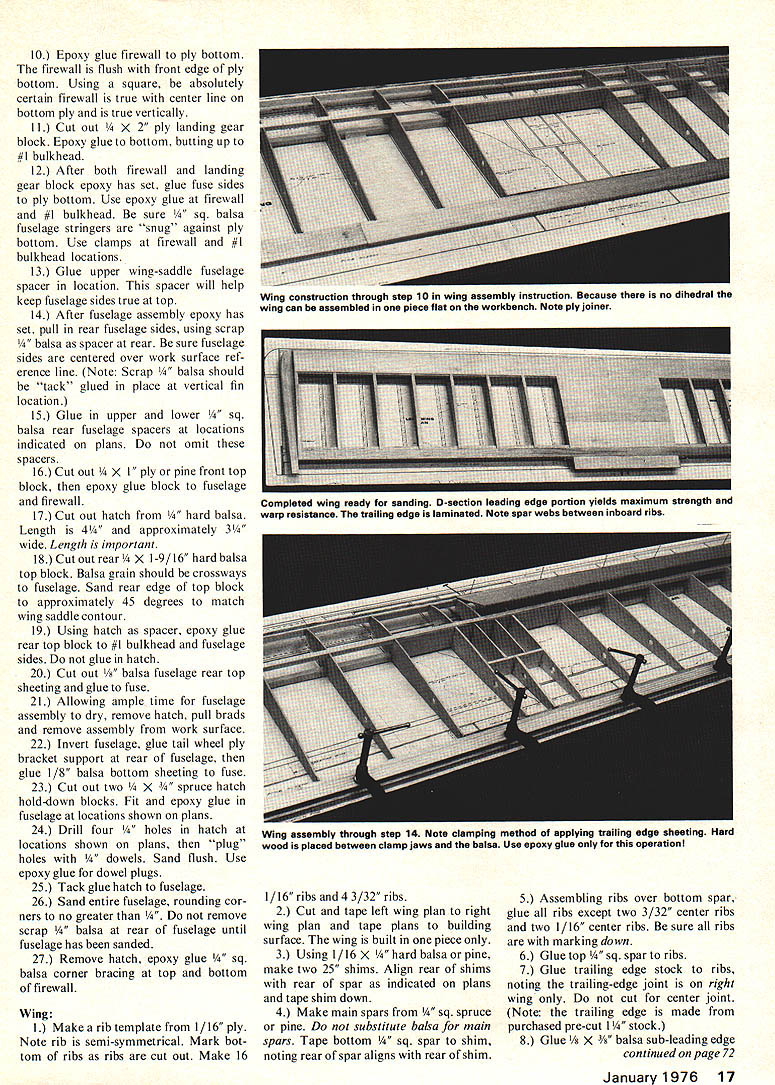
5.) Assembling ribs over bottom spar, glue all ribs except two 3/32" center ribs and two 1/16" center ribs. Be sure all ribs are with markings down.
6.) Glue top 1/4" sq. spar to ribs.
7.) Glue trailing edge stock to ribs, noting the trailing-edge joint is on right wing only. Do not cut for center joint. (Note: the trailing edge is made from purchased pre-cut 1/4" x 5/8" stock.)
8.) Glue 1/8" x 3/8" balsa sub-leading edge stock to ribs. Use epoxy glue only for this operation. provide epoxy "lock."
2.) Bending aluminum brackets slightly outward to provide snug fit in fuselage, install (but don't glue) blocks in fuselage at approximate locations.
3.) Install wing on fuselage, taking extreme care wing is in alignment. Rubber-band wing in position when satisfied with alignment, then mark bottom of wing along fuselage sides for future reference.
4.) Through wing hold-down bolt holes, mark location on wing hold-down blocks in fuselage. (A pencil with about 2" of lead is useful here.)
5.) Remove wing and check for marks in center of wing-hold down blocks. Move blocks in fuselage until marks are centered - install wing, mark and check. When satisfied, mark wing hold-down aluminum bracket locations on fuse.
6.) Remove blocks, drill 13/64" tapping hole, then secure blocks in position using epoxy glue and fiberglass. Fiberglass must be used.
7.) Re-install wing in position, then tap all four wing block holes with 1/4"-20 tap. Tap through wing bolt holes as far as possible with tap, then remove wing and finish tap. This procedure will help correct any misalignment when wing bolt holes are drilled in wing.
Stabilizer—Vertical Fin:
1.) Construct stabilizer, vertical fin, control surfaces, and dorsal fairings from 1/4" balsa sheeting as shown on plans.
2.) Glue tips to stab, vertical fin. Tack glue rudder and elevator, sand stab and vertical fin to shape. Note control surfaces are tapered.
Stabilizer—Fin Installation:
1.) Slide stabilizer into cut-out on fuselage. Make sure stab is centered in fuselage. Measure from stabilizer tips to fuselage center-line at firewall. Mark bottom of stabilizer for reference.
2.) Install wing in place, slide stabilizer in place, then from after end of fuselage, slide forward, observing wing-stab relationship. Be sure wing/stabilizer appears parallel. Sand either cut-out if necessary.
3.) Check stabilizer incidence. A yardstick placed on top of stabilizer, along side of fuselage will line up 3/8" below lower portion of wing saddle.
4.) When satisfied with stabilizer location and incidence, glue stabilizer in place.
5.) Slide vertical fin in place, check for squareness with stabilizer using a square; glue fin in place.
6.) Glue dorsal fairing to vertical fin and fuselage; fairings to stabilizer-fuselage then sand.
Control Surfaces—Hinging: All control surfaces should be beveled at the leading edge, as indicated on plans. Bevel amount should allow surface to move about 30 degrees either side of center.
The use of "living" hinges is recommended. This type of hinge will keep hinge gap to a minimum. Do not allow wide hinge gaps, especially with aileron and elevator. Use at least four hinges for elevator, three per aileron, two for rudder. Instant glue makes for easy hinge installation.
Landing Gear: Either purchase landing gear pre-formed or make from template shown on plans. Secure gear to fuselage with at least two 1/4"-20 nylon bolts. Drill and tap fuselage landing gear block. Use 2 1/4" main gear wheels and 3/4" tail wheel.
Engine, Mount, Fuel Tank: Side-mount engine. This type of mounting provides correct carburetor-fuel tank relationship. Be sure to check for engine offset and down-thrust. A slight amount of right off-set (two degrees max.) won't hurt, but no downthrust.
Finishing: The recommended aircraft finish is Monokote, Solar Film, etc., for weight consideration. This type of finish will not add appreciable weight, is attractive and easy to repair and is durable. It also allows complete sealing of hinge gaps by iron sealing.
CG: Set CG as indicated on plans. If the 4 BITS is to be raced, do not allow CG limits to vary more than plus or minus 1/4". Slightly forward is acceptable but never aft of recommended balance point. more than 1/4", especially aft. Slide battery, servos, etc. fore-aft to obtain balance point. Remember to check CG with all accessories installed (pushrods, fuel tank, prop, etc.).
Control Surface Movements: Initially set up surface movements for the following: Elevator, Aileron — 3/16" up and down; Rudder — 3/8" right and left.
Radio Installation: Use servo trays if possible. The 4 BITS will accept three KPS-12 type servos mounted side-by-side in tray. Use aileron servo side-mount bracket. Wrap battery in foam and install in receiver-servo area. The use of Nyrod is acceptable for rudder, but pushrod should be used for elevator. Be sure aileron control horns are free after installation of wing. Some filing of wing hold-down blocks may be necessary. Use flex cable for engine throttle hook-up.
Flying: The 4 BITS will be very responsive. Set control surface movements to suit individual preference, but never set response to allow a snap-roll if aircraft is to be raced. To find this point, increase elevator throw until snap-roll is obtained, then back off here on one control horn. For general sport flying, set control surface movements limited only by your flying ability. Always, however, start out with "soft" controls.
You'll find the 4 BITS one of the most fun aircraft you've ever flown. In racing, watch out guys....
Transcribed from original scans by AI. Minor OCR errors may remain.

