
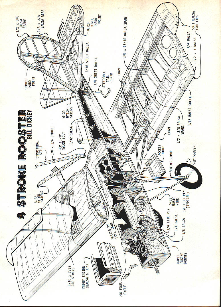
Four-stroke Rooster
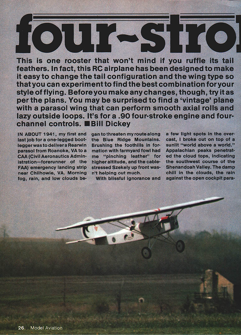
This is one rooster that won't mind if you ruffle its tail feathers. This RC airplane has been designed to make it easy to change the tail configuration and the wing type so you can experiment to find the best combination for your style of flying. Before you make any changes, try it as per the plans. You may be surprised to find a "vintage" parasol that can perform smooth axial rolls and lazy outside loops. It's for a .90 four-stroke engine and four-channel controls. — Bill Dickey
In about 1941, my first and last job for a one-legged bootlegger was to deliver a Rearwin parasol from Roanoke, VA to a CAA emergency landing strip near Chilhowie, VA. Morning fog, rain and low clouds began to threaten my route along the Blue Ridge Mountains. Brushing the foothills in formation with farmyard fowl had me "pinching leather" for higher altitude, and the cable-stressed Szekely up front wasn't helping much. With blissful ignorance and a few light spots in the overcast, I broke out on top of a sunlit "world above a world." Appalachian peaks penetrated the cloud tops, indicating the southwest course of the Shenandoah Valley. The damp chill in the clouds, rain against the open-cockpit parasol, and the lonely beauty above the clouds made an impression on a teenage dodo that thousands of military and civilian flying hours afterwards did not erase.
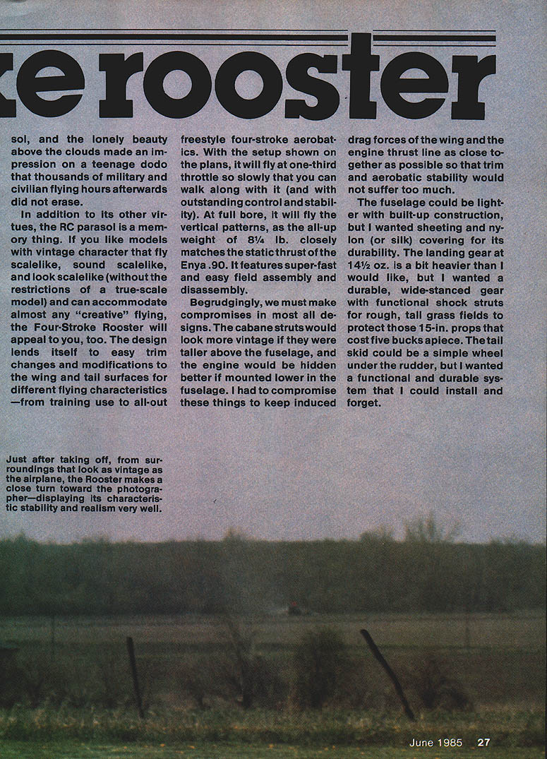
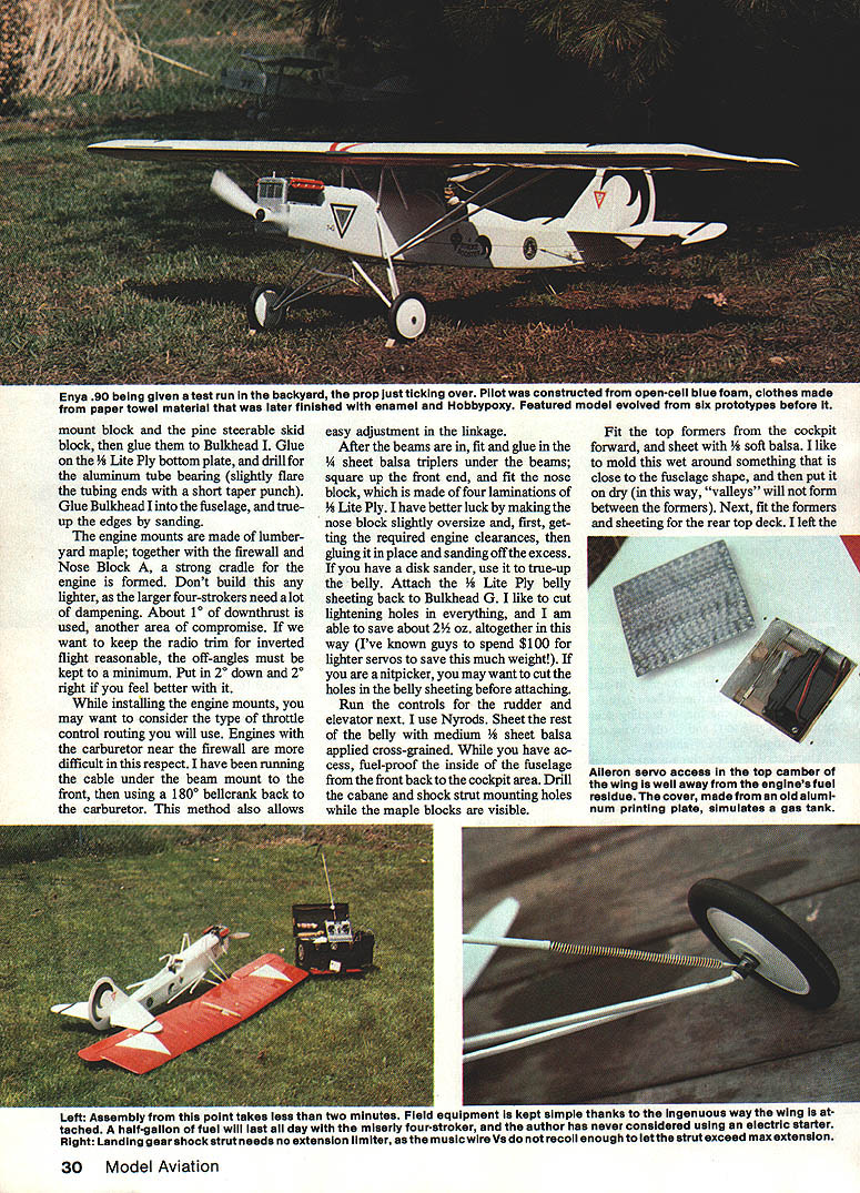
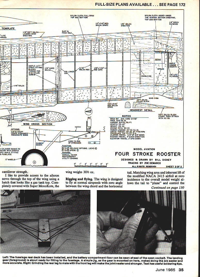
In addition to its other virtues, the RC parasol is a memory thing. If you like models with vintage character that fly scale-like, sound scale-like and look scale-like (without the restrictions of a true-scale model) and can accommodate almost any "creative" flying, the Four-Stroke Rooster will appeal to you. The design lends itself to easy trim changes and modifications to the wing and tail surfaces for different flying characteristics — from training use to all-out freestyle four-stroke aerobatics. With the setup shown on the plans, it will fly at one-third throttle so slowly you can walk along with it (with outstanding control and stability). At full bore, it will fly the vertical patterns, as the all-up weight of about 8-1/4 lb closely matches the static thrust of the Enya .90. It features super-fast and easy field assembly and disassembly.
Begrudgingly, we must make compromises in most designs. The cabane struts would look more vintage if taller above the fuselage, and the engine would be hidden better if mounted lower. I compromised these to keep induced drag forces of the wing and the engine thrust line as close together as possible so trim and aerobatic stability would not suffer too much.
The fuselage could be lighter with built-up construction, but I preferred sheeting and nylon (or silk) covering for durability. The landing gear at 14-1/2 oz is a bit heavier than I would like, but I wanted a durable, wide-stanced gear with functional shock struts for rough, tall-grass fields to protect those 15-in. props that cost five bucks apiece. The tail skid could be a simple wheel under the rudder, but I wanted a functional, durable system I could install and forget.
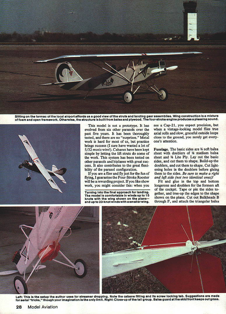
This model is not a prototype. It evolved from six other parasols over five years. It has been thoroughly tested, and there are no "surprises." Metal work is hard for most of us, but practice brings success. Cabanes have been kept simple by letting the lift struts do some of the work. This system has been tested on other parasols and biplanes with great success and contributes to the flexibility of the parasol configuration.
If you fly just for the fun of flying, I guarantee the Four-Stroke Rooster will be a rewarding project. If you like show work, consider this: when a vintage-looking model flies true axial rolls and slow, graceful outside loops close to the ground, you get everyone's attention.
Fuselage
The basic sides are 1/8" soft balsa sheet with doublers of 1/4" medium balsa and 1/8" Lite Ply. Lay out the basic sides and cut them to shape. Build up the doublers and cut them to shape. Cut lightening holes in the doublers before gluing them to the sides. Be sure to make a right and a left side (not two identical ones).
Fit and glue in the top and bottom longerons and doublers to the formers aft of the cockpit. Tape or pin the sides together and true up the edges to the shape shown on the plans. Cut out bulkheads B through F and attach the triangular balsa blocks.
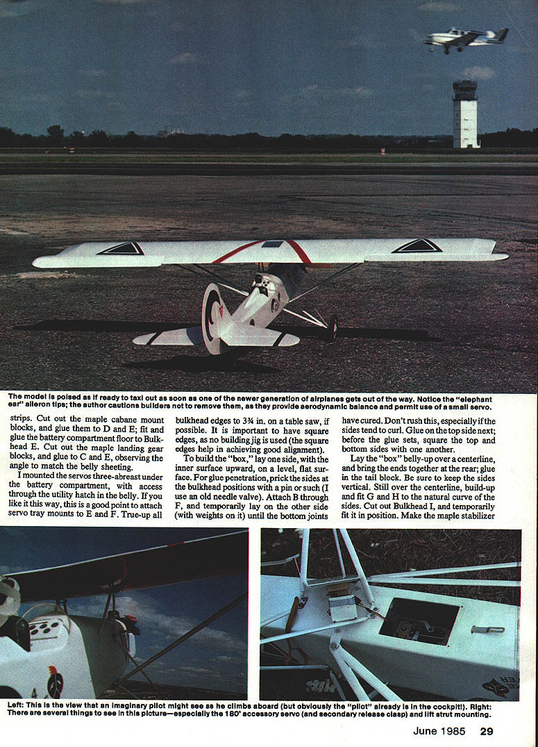
Cut out the maple cabane mount blocks and glue them to bulkheads D and E. Fit and glue the battery compartment floor to bulkhead E. Cut out the maple landing-gear blocks and glue them to bulkheads C and E, observing the angle to match the belly sheeting.
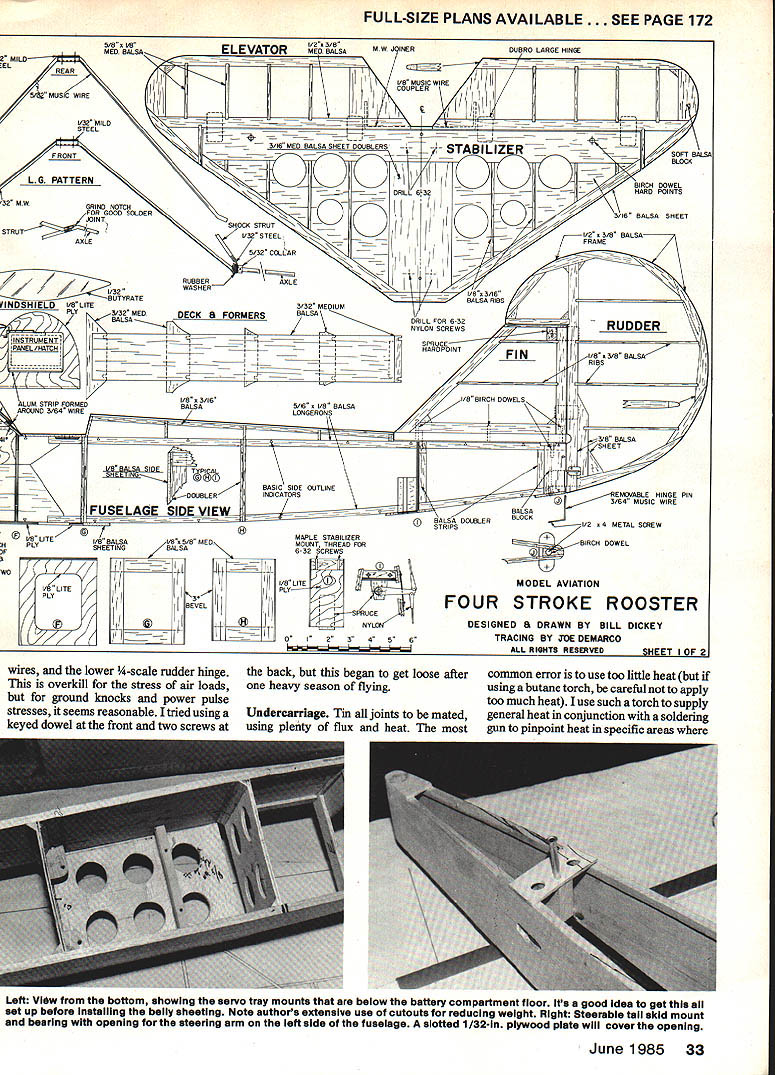
I mounted the servos three abreast under the battery compartment, with access through the utility hatch in the belly. If you like this layout, attach servo-tray mounts to E and F now.
True up all bulkhead edges to 3/4" on a table saw, if possible. Square edges are important because no building jig is used — the square edges help achieve good alignment.
To build the box:
- Lay one side with the inner surface upward on a level, flat surface.
- Prick the sides at the bulkhead positions for glue penetration (an old needle valve works).
- Attach bulkheads B through F and temporarily lay the other side over them (weights on it) until the bottom joints have cured.
- Don't rush — sides tend to curl.
- Glue the top side next before the glue sets, and square the top, bottom and sides together.
Lay the box belly-up over a centerline and bring the ends together; rear-glue the tail block. Keep the sides vertical. While still over the centerline, build up and fit formers G and H to the natural curve of the sides. Cut out bulkhead I and temporarily fit it in position. Make the maple stabilizer mount block and glue it in place.
Glue the ply bottom plate and drill the aluminum tube bearing. Slightly flare the tubing ends and short-taper punch them as required. True up the fuselage edges by sanding. Engine mounts are made from lumber-yard maple and are glued to the firewall. The nose block is a strong cradle for the engine formed in place; make it slightly oversize, fit to obtain required clearances, then glue and sand to final shape.
Don't build it lighter or larger — four-strokers need a lot of dampening. Another area of compromise is keeping radio trim for inverted flight reasonable; off-angles must be kept to a minimum. I found that 2° down and 2° right feels better. About 1° downthrust is used on this design.
When installing the engine mounts consider throttle-control routing. Engines with the carburetor near the firewall make running the throttle cable under the beam-mounted front difficult. I use a 1/8" bellcrank at the carburetor/back method, which also allows easy linkage adjustment.
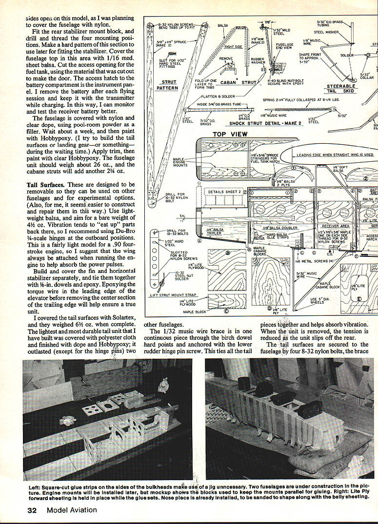
After the beams fit, glue sheet-balsa triplers under the beams; square up the front end and fit the nose block (four laminations of 1/8" Lite Ply). If you have a disk sander, use it to true up the belly. Attach the 1/8" Lite Ply sheeting back to bulkhead G. Cut lightening holes wherever practical; I saved about 2-1/2 oz this way.
Run the controls for the rudder and elevator next; I use Nyrods. Sheet the rest of the belly with medium 3/32" sheet balsa applied cross-grained. While you have access, fuel-proof the inside of the fuselage from the front back to the cockpit area. Drill the cabane and shock-strut mounting holes while the maple blocks are visible.
Fit the top formers from the cockpit forward and sheet with 1/8" soft balsa. I like to mold this wet around something close to the fuselage shape, then fit it dry to avoid valleys between formers. Next fit the formers and sheeting for the rear top deck. On this model the sides are left open during construction since I planned to cover the fuselage with nylon.
Fit the rear stabilizer mount block and drill and thread the four mounting positions. Make a hard pattern of this section for later stabilizer fitting. Cover the fuselage top in this area with 1/16" medium sheet balsa. Cut the access opening for the fuel tank, using the material removed as the door. The access hatch to the battery compartment is the instrument panel. I remove the battery after each flying session and keep it with the transmitter while charging so I can monitor and test the receiver battery.
Cover the fuselage with nylon and clear dope, using pool-room powder as a filler. Wait about a week, then paint with Hobbypoxy. Apply trim, then finish with clear Hobbypoxy. The fuselage unit should weigh about 26 oz; the cabane struts will add another 2-1/4 oz.
Tail Surfaces
The tail surfaces are designed to be removable so they can be used on other fuselages and for experimental options. Use lightweight balsa and aim for a bare weight of about 4-1/2 oz. Vibration tends to "eat up" parts back there, so I recommend Du-Bro 1/4-scale hinges at the outboard positions. This is a fairly light tail for a .90 four-stroke, so I suggest the wing always be attached when running the engine to help absorb power pulses.
Build and cover the fin and horizontal stabilizer separately and tie them together with 1/8" dowels and epoxy. Epoxying the torque wire in the leading edge of the elevator before removing the center section of the trailing edge helps ensure a true unit.
I covered the tail surfaces with Solartex; they weighed 6-1/2 oz when complete. The lightest and most durable tail I built was covered with polyester cloth and finished with dope and Hobbypoxy; it outlasted two other fuselages (except for hinge pins).
A 1/32" music-wire brace runs in one continuous piece through birch dowel hard points and is anchored with the lower rudder hinge pin screw. This ties all the tail pieces together and helps absorb vibration. When the unit is removed, the tension is reduced as the unit slips off the wires. This overbuild is for ground knocks and power-pulse stresses; a keyed dowel at the front and two screws at the back tended to loosen after heavy use.
Undercarriage
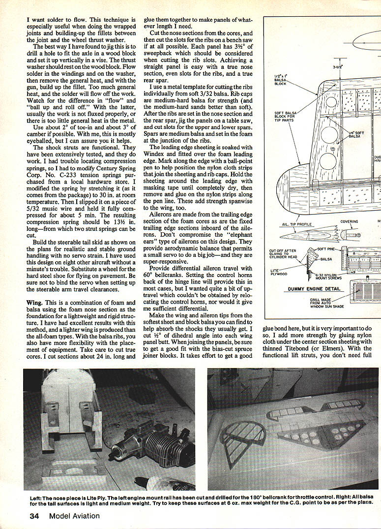
Tin all joints to be mated, using plenty of flux and heat. The most common error is using too little heat. I use a butane torch for general heat and a soldering gun to pinpoint heat in areas where the tin must melt and flow. This is especially useful for wrapped joints and building fillets between the joint and the wheel thrust washer.
Jigging method:
- Drill a hole to fit the axle in a wood block and set it up vertically in a vise.
- Let the thrust washer rest on the wood block.
- Flow solder in the windings and on the washer, then remove general heat and use the soldering gun to build up the fillet.
Watch the solder flow: if it balls up and rolls off, the work is not fluxed properly or lacks general heat.
Use about 2° of toe-in and about 3° of camber if possible. I mostly eyeball this, but it helps.
The shock struts are functional. I had trouble locating compression springs, so I modified Century Spring Corp. No. C-233 tension springs. I stretched the spring to 30" at room temperature, slipped it on a piece of 5/32" music wire and held it fully compressed for about 5 minutes. The resulting compression spring should be about 13-1/2" long — two short springs can be cut from one modified spring.
Build the steerable tail skid as shown on the plans for realistic and stable ground handling with no servo strain. Substitute a wheel for the steel shoe when flying on pavement. Be sure not to bind the servo when setting up the steerable arm travel clearances.
Wing
This wing is a combination of foam and balsa using the foam nose section as the foundation for a lightweight, rigid structure. This produces a lighter wing than all-foam types and gives flexibility for equipment placement.
Construction overview:
- Cut foam cores in sections about 24" long and glue them together to make panels of the required length.
- Cut the nose sections from the cores, then cut slots for the ribs on a bench saw if possible. Each panel has 3.75° of sweepback, which must be considered when cutting rib slots.
- Use a metal template to cut ribs from soft 3/32" balsa. Rib caps are medium-hard balsa for strength.
- After setting ribs in the nose section and rear spar, jig the panels on a table saw and cut slots for the upper and lower spars. Spars are medium balsa and set in the foam at the junction of the ribs.
Leading edge and sheeting:
- Soak the leading edge sheeting with Windex and fit it over the foam leading edge. Mark along the edge with a ballpoint pen to position nylon cloth strips that join the sheeting and rib caps.
- Hold the sheeting around the leading edge with masking tape until completely dry, then remove and glue on the nylon strips along the pen line. These strips add spanwise strength.
Ailerons and control:
- Ailerons are made from the trailing-edge section of the foam cores, as are the fixed trailing-edge sections inboard of the ailerons.
- Don't compromise the "elephant-ear" ailerons on this design. They provide aerodynamic balance that permits a small servo to do a big job and are very responsive.
- Provide differential aileron travel with 60° bellcranks. Setting the control horns back of the hinge line will provide some differential, but I wanted quite a bit of up travel which couldn't be obtained solely by relocating the control horns.
Joinery and tips:
- Make wing and aileron tips from the softest sheet and block balsa you can find to help absorb shocks.
- Cut 1/2° of dihedral into each wing-panel butt. When joining panels, get a good fit with bias-cut spruce joiner blocks and use effort to obtain a strong glue bond.
- Add strength by gluing nylon cloth under the center-section sheeting with thinned Titebond or Elmer's. With functional lift struts, full gusseting is not required, but give the center section extra attention.
Covering and weight:
- I provide access to the aileron servo through a hatch that looks like a gas-tank top.
- Completely covered with Super MonoKote, the wing weighs about 30-1/2 oz.
Turning final approach and landing is comfortable in winds up to 15 knots. The wing shown will handle up to 20-knot winds; a smaller wing is suggested for lighter-air flying. Expect a precision, vintage-looking model that flies true, will do axial rolls, slow graceful outside loops close to the ground, and will get attention.
Rigging and Flying
Balance the model carefully at the point shown on the plans. After balancing, don't change the balance point trying to chase trim problems.
Trim notes:
- If down-elevator is needed to hold level flight, it doesn't mean the tail is heavy. The wing may be lifting the tail out of "plane." Decrease the tail lift by slightly raising the wing trailing edge (this doesn't reduce the overall lifting capability of the wing as much as you might think).
- The lift-strut mount is provided with slots to adjust the wing for these problems.
- At proper trim the wing profile view may appear to have negative incidence if the aircraft is close to design weight. If overweight, you might have to add positive incidence to the wing to achieve tail trim.
- Balance the model along the roll axis; nails pushed into the soft wing tips will usually correct any imbalance.
Control setup and flying technique:
- Set the control throws for the amounts shown on the plans. This produces quick responses needed for creative maneuvers.
- Use elevator back pressure in turns and glides; forward elevator pressure for inverted flight.
- Use right rudder on takeoffs and climbs; use lots of rudder in slips and vary opposite aileron to hold track.
- For knife-edge flight, use almost full top rudder.
- Normal and outside snap rolls are easy, and recovery is positive (also with normal and inverted spins).
- Flat turns with rudder are stable and attractive; keep some power on.
- Fly it at half-power for an outstanding trainer that is stable and responsive.
- Work for a low engine idle; the differential between top rpm and idle is relatively small in four-strokers. Low idle is required for realistic glides, safe taxiing, and maneuvers such as takeoff-loop-land where back-side airspeed must be kept low.
Use other wings for added pleasure:
- A heavier-loaded, low-aspect wing (about 24 oz per sq. ft.) is good for high winds.
- Try a STOL-type wing with Clark-Y airfoil and flaps and/or slots for short-field flying.
- Use accessory hatches for bomb dropping, banner towing, tissue or parachute dropping, photography, etc.
Field assembly and disassembly:
- Loosen six nylon bolts about three turns.
- Unplug the aileron servo.
- Snap the wing and struts out of their mounts and fold the lift struts back against the fuselage.
- It takes less than two minutes with no screws to lose or threads to bind.
This system works very well. The metalwork is not as difficult as it may appear — just be sure the "tacks" match the screw heads. I know you will like this versatile, functional and durable vintage-type airplane.
Transcribed from original scans by AI. Minor OCR errors may remain.

