
The Fox
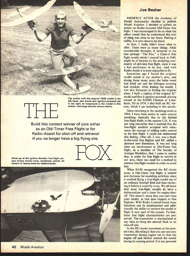
Build this contest winner of yore either as an Old-Timer Free Flight or for Radio-Assist for shut-off and retrieval if you no longer have a big flying site.
Joe Beshar
SHORTLY AFTER the Academy of Model Aeronautics decided to publish Model Aviation, I decided to submit an article on Radio-Assisted Old-Timer free flight. I was encouraged to do so when the editor stated that he understood this sort of thing was close to my heart. Putting it mildly, it is very close to my heart.
At first, I really didn't know what to offer. There were so many things. After considerable thought, it occurred to me that perhaps "The Fox," a Class-A free flight model which I created back in 1940, might be of interest to the modeling community of old-time free flight, since it was a fine performer in its day. And with Radio-Assist it is most enjoyable to fly.
Sometime ago I found the original model stored in my mother's attic, and during those many years the balsa wood had dried out and the Silkspan covering had cracked. After finding the model, I was also fortunate in finding the original plans. I built a replica of the original 42" model and flew it ignition-powered, placing second at the SAMS Champs at Lakehurst, NJ in 1974. I also built an RC version, which I am including in this article.
Since returning to the modeling circle in 1964, I have been active in radio control modeling, basically due to the limited free-flight fields in the eastern U.S. It was not long thereafter that I realized that the free-flight modeler accepted with reluctance the concept of adding radio control to his free flight. I could not understand this feeling. After all, I, too, was a dyed-in-the-wool free flighter and RC added a pleasant new dimension. It was not long after my involvement in Old-Timer free flight, as a member of The Society of Antique Modelers, that I came to realize that, in order for free flight to survive in our area, there was need for a method to retrieve free-flight models in order to avoid loss.
When SAM recognized the RC-Assist event in Old-Timer free flight, it opened new horizons for modeling activities, since it enabled flying a free-flight model out of an ordinary football field and then retrieving it before it could fly away. We all know that most free-flight models do have a dethermalizer and a timer for engine shut-off. This doesn't mean that you can't lose your model, as that does happen to free fighters. With Radio Control-Assist these functions can be implemented and additionally the ability to retrieve the model in flight is now part of the system. Further, basic free flight characteristics are preserved. The transmitter is manipulated at any time to bring the aircraft back to its take-off site.
In the RC-Assist movement at the present time, the ruling is that you can use your transmitter during engine run to shut the engine off and further control the model during its soaring period. It is my personal goal, which I am confident will happen in the future, that the rules state that the transmitter be used to shut the engine off, subsequently allowing the model to perform according to its normal free flight characteristics without the use of the transmitter, as was the case in all free flight activities. In the event that the model is caught in a thermal, or is in any kind of trouble, the modeler decides to use the radio to control the model. The moment he uses his transmitter for control the flight would be considered over.
Please note that this is my personal goal. I feel this would restore the true free flight characteristics, requiring the skills to trim such a model. All that would be different would be the ability to return the model to its launching point only in the event that it was in trouble and the modeler saw fit to control it.
It has been an honor for me to be the president of The Society of Antique Modelers and in this circle of free flight activity it is my ultimate aim to obtain acceptance to this type of ruling. Further, it is my humble feeling that for all free flight, including modern free flight activity, it is only a matter of time that this type of RC-Assist will have to be employed in order for free flight to survive. The reason for this is that in many areas there are just no free-flight fields for a modeler to do his thing, unless he travels 50 to 100 miles out of town. Even then it can be tricky. But enough of my theories. Let's go on with the Fox.
Initially, I will describe the construction of the Fox as the original ignition-powered Class A model, and then follow with the supplements necessary to adapt it for RC-Assist. In presenting the article in this manner it will enable the modeler to apply these principles of RC-Assist to any old-time or modern free-flight model.
Fuselage
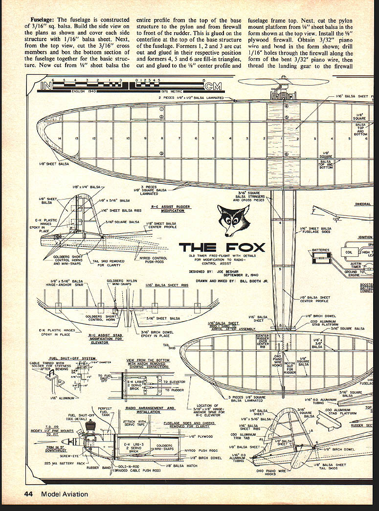
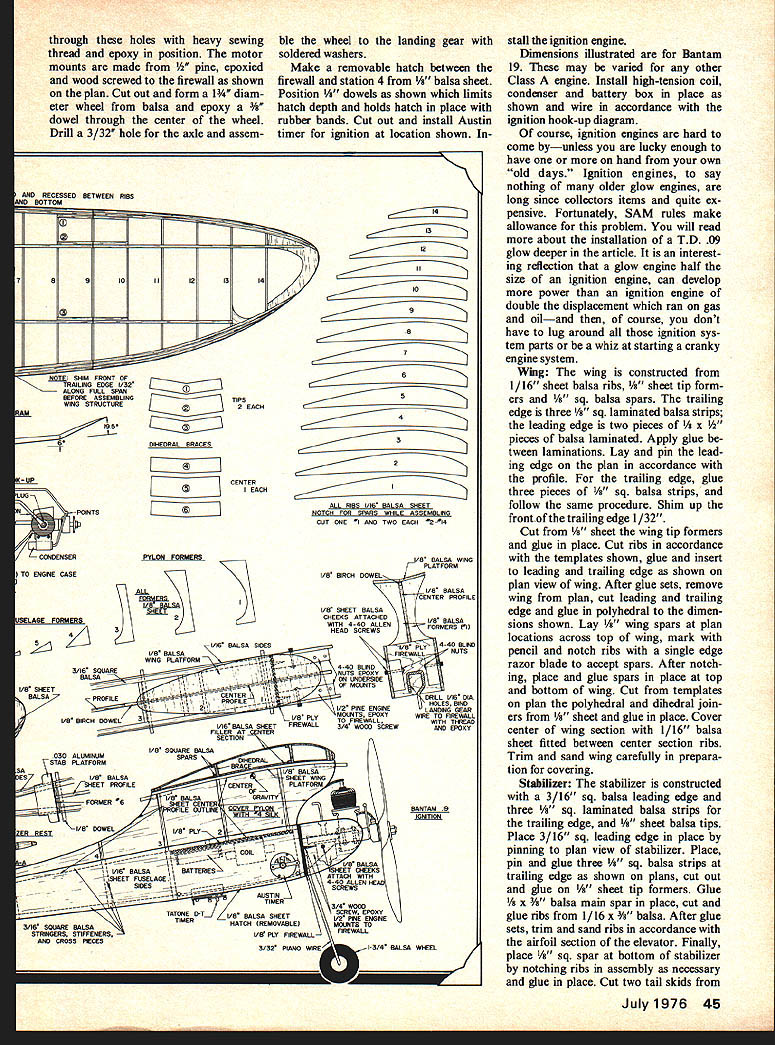
The fuselage is constructed of 3/16" sq. balsa. Build the side view on the plans as shown and cover each side structure with 1/16" balsa sheet. Next, from the top view, cut the 3/16" cross members and box the bottom section of the fuselage together for the basic structure. Now cut from 1/8" sheet balsa the entire profile from the top of the base structure to the pylon and from firewall to front of the rudder. This is glued on the centerline at the top of the base structure of the fuselage. Formers 1, 2 and 3 are cut out and glued in their respective position and formers 4, 5 and 6 are fill-in triangles, cut and glued to the 1/8" center profile and fuselage frame top. Next, cut the pylon mount platform from 1/8" sheet balsa in the form shown at the top view. Install the 1/8" plywood firewall. Obtain 3/32" piano wire and bend in the form shown; drill 1/16" holes through the firewall along the form of the bent 3/32" piano wire, then thread the landing gear to the firewall. through these holes with heavy sewing thread and epoxy in position. The motor mounts are made from 1/2" pine, epoxied and wood screwed to the firewall as shown on the plan. Cut out and form a 1 1/4" diameter wheel from balsa and epoxy a 3/8" dowel through the center of the wheel. Drill a 3/32" hole for the axle and assemble the wheel to the landing gear with soldered washers.
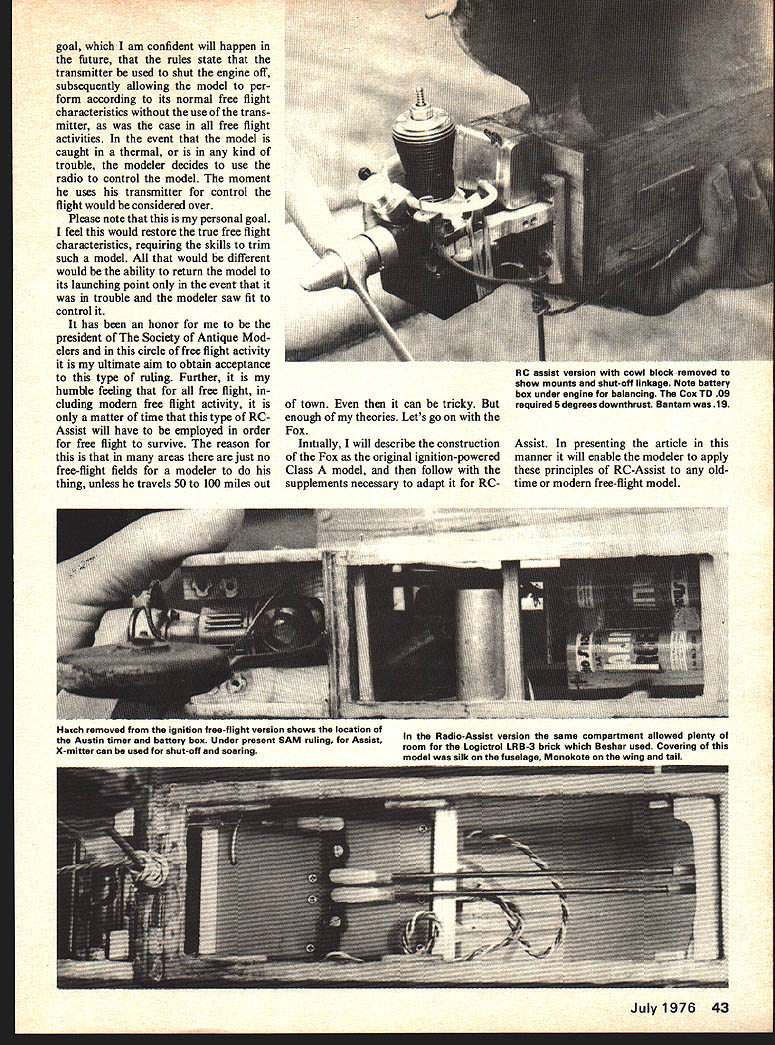
Make a removable hatch between the firewall and station 4 from 1/8" balsa sheet. Position 1/4" dowels as shown which limits hatch depth and holds hatch in place with rubber bands. Cut out and install Austin timer for ignition at location shown.
Dimensions illustrated are for Bantam 19. These may be varied for any other Class A engine. Install high-tension coil, condenser and battery box in place as shown and wire in accordance with the ignition hook-up diagram.
Of course, ignition engines are hard to come by — unless you are lucky enough to have one or more on hand from your own "old days." Ignition engines, to say nothing of many older glow engines, are long since collectors' items and quite expensive. Fortunately, SAM rules make allowance for this problem. You will read more about the installation of a T.D. .09 glow deeper in the article. It is an interesting reflection that a glow engine half the size of an ignition engine can develop more power than an ignition engine of double the displacement which ran on gas and oil — and then, of course, you don't have to lug around all those ignition system parts or be a whiz at starting a cranky engine system.
Wing
The wing is constructed from 1/16" sheet balsa ribs, 1/8" sheet tip formers and 1/8" sq. balsa spars. The trailing edge is three 1/8" sq. laminated balsa strips; the leading edge is two pieces of 1/4" x 1/2" pieces of balsa laminated. Apply glue between laminations. Lay and pin the leading edge on the plan in accordance with the profile. For the trailing edge, glue three pieces of 1/8" sq. balsa strips, and follow the same procedure. Shim up the front of the trailing edge 1/32".
Cut from 1/8" sheet the wing tip formers and glue in place. Cut ribs in accordance with the templates shown, glue and insert to leading and trailing edge as shown on plan view of wing. After glue sets, remove wing from plan, cut leading and trailing edge and glue in polyhedral to the dimensions shown. Lay 1/8" wing spars at plan locations across top of wing, mark with pencil and notch ribs with a single edge razor blade to accept spars. After notching, place and glue spars in place at top and bottom of wing. Cut from templates on plan the polyhedral and dihedral joiners from 1/8" sheet and glue in place. Cover center of wing section with 1/16" balsa sheet fitted between center section ribs. Trim and sand wing carefully in preparation for covering.
Stabilizer
The stabilizer is constructed with a 3/16" sq. balsa leading edge and three 1/8" sq. laminated balsa strips for the trailing edge, and 1/8" sheet balsa tips. Place 3/16" sq. leading edge in place by pinning to plan view of stabilizer. Place, pin and glue three 1/8" sq. balsa strips at trailing edge as shown on plans, cut out and glue on 1/8" sheet tip formers. Glue 1/8" x 3/8" balsa main spar in place, cut and glue ribs from 1/16" x 3/8" balsa. After glue sets, trim and sand ribs in accordance with the airfoil section of the elevator. Finally, place 1/8" sq. spar at bottom of stabilizer by notching ribs in assembly as necessary and glue in place. Cut two tail skids from
The Fox
1/8" sheet, contoured as shown, in readiness for installation after covering.
Rudder
Construct the rudder from a 3/16" sq. balsa leading edge, a 1/16" sheet trailing edge, by cutting and gluing on plan view. Next, raise outline of rudder 1/16" off plan by packing. Assemble and glue 1/8 x 5/16" balsa main spar with 1/16 x 5/16" ribs. Bottom rib is cut from 3/32" balsa sheet. After glue has dried remove from plan, trim to airfoil section and sand for final rudder configuration.
Covering
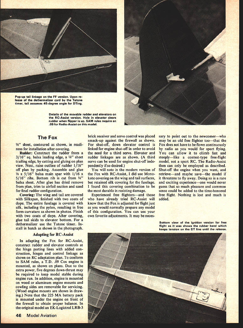
The wing and tail are covered with Silkspan, finished with two coats of dope. The entire fuselage is covered with silk, including the pylon, resulting in free-form curvature as shown in photos. Finish with two coats of dope. After covering, glue tail skids to elevator bottom. For a dethermalizer use the Tatone timer. Install in hatch as shown in the photograph.
Adapting for RC-Assist
In adapting the Fox for RC-Assist, construct rudder and elevator controls at the hinge parting lines with added construction, hinges and control linkage as shown on RC adaption plan. To conform to SAM rules, a T.D. .09 Cox engine is mounted, as shown on plans. Due to the extra power, five degrees down-thrust may be required to keep model stable during engine run. In addition, engine is mounted on wood or aluminum engine mounts and cowlings are removable for servicing. (Wood engine mounts are shown in drawing.) Note that the 225 MA battery pack is mounted under the engine on front of the firewall to obtain proper balance. In the original model an EK-Logictrol LRB-3 brick receiver and servo control was placed smack-up against the firewall as shown.
For shut-off, down-elevator control is linked for engine shut-off in order to avoid the need for a third servo. Elevator and rudder linkages are as shown. (A third servo can be used for engine shut-off independently if so desired.)
You will note in the modern version of the Fox with RC-Assist, I did use Monokote covering on the wing and tail surfaces, but retained silk covering for the fuselage. I found this covering combination to be the most durable in resisting damage.
Experienced free fighters — and those who have already tried RC-Assist — will know that the Fox is adjusted for flight just as you would normally prepare any model of this configuration. You can use your own favorite adjustments. It may be necessary to point out to the newcomer — who may be an old free fighter too — that the Fox does not have to be flown continuously by radio as you would for sport flying. You can allow it to climb fast and steeply — like a contest-type free-flight model, not a sport RC. The Radio-Assist then can only be employed as described. Shut off the engine when you want, and retrieve — and maybe save — the model if it threatens to fly away. Doing so is a rare and exciting experience — one would never guess that so much pleasure and common sense could be added to the time-honored free flight. Nothing is lost and much is added.
Transcribed from original scans by AI. Minor OCR errors may remain.

