
Foxbat 330 - 2005/01
by Frank Roberge
Modern 1/2A Open FF Gas model features variable-incidence tailplane
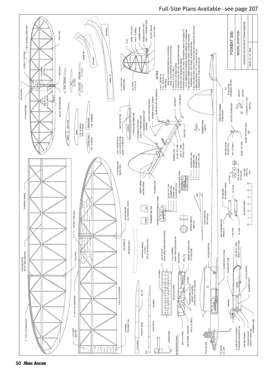
FOXBAT WAS DESIGNED to be a modern Category II and III Open 1/2A Gas model. To accomplish this goal, a Cyclon .049 engine (KCs, ADs, and Foras are also suitable) is combined with a Variable Incidence Tailplane (VIT) system and an electronic timer in a model size that allows a good balance between climb and glide performance. My secondary goal was to achieve this at a reasonable level of building effort and produce a design that the average FF modeler could build successfully. Foxbat incorporates the following features:
- A flat-bottomed airfoil, to avoid the need for a contoured building bed while allowing the use of a full-depth spar.
- A modest wing aspect ratio (approximately 10:1), to allow a vertical climb and smooth transition using a VIT without bunt.
Foxbat has served me well. In addition to many wins in local contests, the model placed first in 1/2A Open Gas at the 2003 and 2004 Southwest Regionals.
CONSTRUCTION
Build and cover the wing, stabilizer, and rudder first, so that they are available when you are building and rigging the fuselage.
Wing
The heart of the wing is the spar, which is full depth and capped with .007-inch-thick unidirectional carbon fiber (CF).
Attach a piece of waxed paper to a flat 3/4- or 1-inch-thick building board using 3M Super 77 spray cement. Cover two pieces of 1-inch aluminum angle with waxed paper on their outer surfaces using 3M Super 77. Affix one piece 3 inches from the edge of the board with 3M Super 77. Cut a 3/16 x 1 x 29-inch spar blank and a 3/16-inch-wide strip of .007-inch CF. Spread a thin layer of good-quality epoxy, such as NHP 12-minute, to one edge of the spar blank and add the CF strip. Lay the assembly flat on the building board with the CF against the face of the aluminum angle. Press the vertical face of the second angle against the back edge of the spar and clamp with six or seven large spring clamps. Remove the spar subassembly when cured, and cut one piece to 17-1/2 inches for the main spar. The leftover 11-1/2-inch piece will be the tip spar. Carefully cut the main spar to the exact height of the main spar shown on the rib-section drawing of the plans, minus the thickness of the top .007 CF strip, and add the second CF strip. To complete the tip spar, make a 1/32 plywood template from the wingtip spar drawing. Transfer the shape to the 11-1/2-inch piece and cut to shape and length. There is no CF on the top surface.
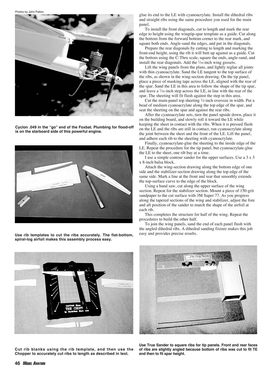
Because the airfoil is a log spiral, you only need three templates per wing. Make the three wing-rib templates using the rib drawings for the main, front diagonal, and rear diagonal ribs. Make the templates as shown in the "typical rib template" drawing. Place the rib template—upside down—on the rib sheet stock with the hardwood strip butted against the lower edge. Cut the rib profile and then the vertical LE and TE cuts. The forward vertical edge of the ribs must be square with the bottom of the rib. The tip TEs are first assembled as blanks with sandable aliphatic resin glue, using 3/16 x 1-inch strips. Then they are cut as one piece using the wingtip template provided on the plans.
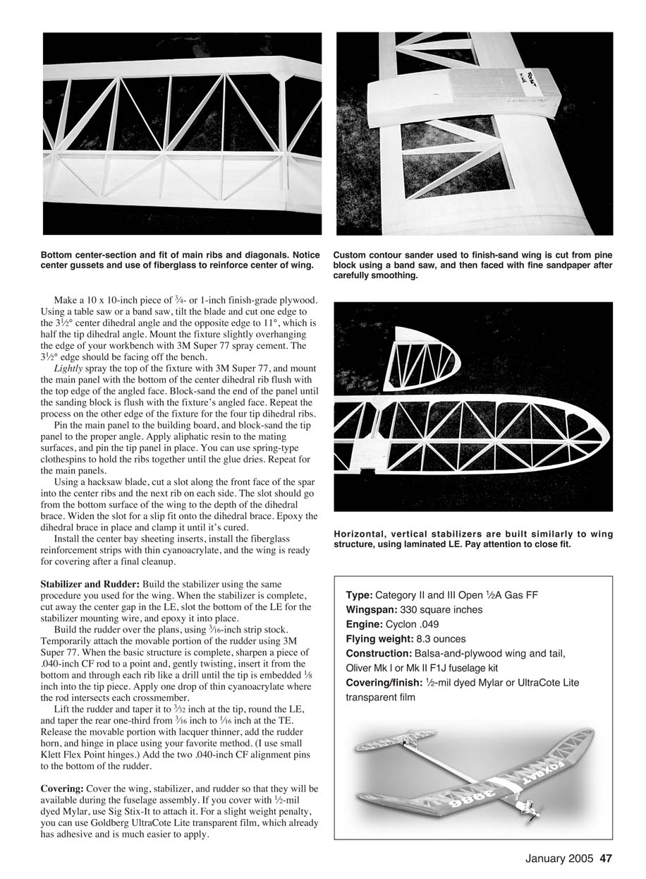
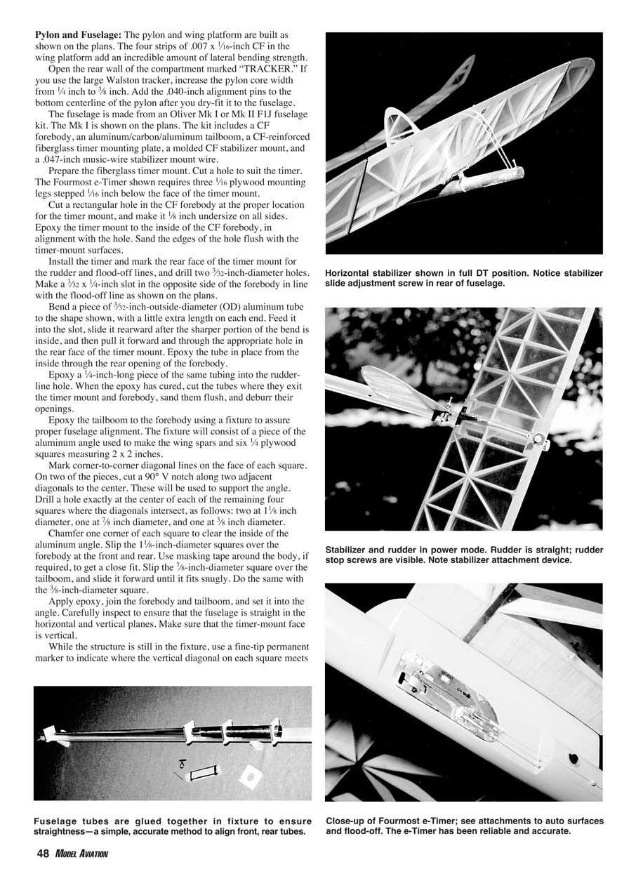
To assemble the wing, cover the plans with waxed paper and pin down the main panel TE, spar, and two-piece LE. Use Rocket City pin clamps for all parts pinning to avoid putting pins through the balsa. Use aliphatic resin for assembly of all laminated LEs. Carefully cut the forward portion of one rib to fit between the LE and the spar. It is essential that all cuts are perpendicular to the bottom of the rib to assure a good glue joint with the spar. To make sure of this, I use Micro-Mark's heavy-duty Chopper II and True Sander tools. When you are satisfied with the fit of the first rib, place it on the Chopper with the spar end against the blade, and set the adjustable stop against its LE. Cut all of the main-panel front ribs to this length. Cut a 1/16-inch strip from the bottom of each front rib using a Master Airscrew balsa stripper. Install the 3/32-inch dihedral ribs, at the appropriate angles, using the dihedral-rib fixtures provided on the plans. Put in the remainder of the ribs, ensuring that they are properly aligned and perpendicular to your building board.
Set the Chopper's stop to the thickness of the spar, cut from the front edge of each main-rib leftover, and install. Install the front diagonal ribs after you cut them to length (slice from the rear face), and sand the front and rear faces to an angle for a flush fit to the LE and the spar. Repeat for the rear diagonals.
To build the tip panel, cut each rib to length. Scribe a mark 3/16 inch from one edge of a C-Thru plastic scale, place the scale over the rib so that the edge is on the front bottom corner and the mark is on the rear top corner, and cut away the bottom. Square both ends with the True Sander.
Pin down the TE and put a series of T-pins along the inside of the LE, between the rib locations. Cut four strips of 1/16 x 2-1/2-inch balsa, and glue them together to make the tip spar. Clean up the excess glue, and pin along the LE against the T-pins before the glue sets. After the LE dries, pin down the spar and glue its end to the LE with cyanoacrylate. Install the dihedral ribs and straight ribs using the same procedure you used for the main panel.
To install the front diagonals, cut to length and mark the rear edge to height using the wingtip-spar template as a guide. Cut along the bottom from the forward bottom corner to the rear mark, and square both ends. Angle-sand the edges, and put in the diagonals.
Prepare the rear diagonals by cutting to length and marking the front-end height, using the rib it will butt up against as a guide. Cut the bottom using the C-Thru scale, square the ends, angle-sand, and install the rear diagonals. Add the 1/16-inch wing gussets.
Lift the wing panels from the plans, and lightly reglue all joints with thin cyanoacrylate. Sand the LE tangent to the top surface of the ribs, as shown in the wing-section drawing. On the tip panel, place a piece of masking tape across the LE, aligned with the rear of the spar. Sand the LE in this area to follow the shape of the tip spar, and leave a 1/16-inch step across the LE, in line with the rear of the spar. The sheeting will fit flush against the step in this area.
Cut the main-panel top sheeting 1/4-inch oversize in width. Put a bead of medium cyanoacrylate along the top edge of the spar, and seat the sheeting on the spar and against the rear ribs.
After the cyanoacrylate sets, turn the panel upside down, place it on the building board, and slowly roll it toward the LE while keeping the sheet in contact with the ribs. When it is pressed flush on the LE and the ribs are still in contact, run cyanoacrylate along the joint between the sheet and the front of the LE. Lift the panel, and adhere each rib to the sheeting with cyanoacrylate.
Finally, cyanoacrylate-glue the sheeting to the inside edge of the LE. Repeat the procedure for the tip panel, but cyanoacrylate-glue the LE to the sheet, one rib bay at a time.
I use a simple contour sander for the upper surfaces. Use a 3 x 3 x 8-inch balsa block.
Attach the wing-section drawing along the bottom edge of one side and the stabilizer-section drawing along the top edge of the same side. Mark a line at the front and rear that smoothly extends the top-surface curve to the edge of the block.
Using a band saw, cut along the upper surface of the wing section. Repeat for the stabilizer section. Mount a piece of 150-grit sandpaper to the cut surface with 3M Super 77. As you progress along the tapered sections of the wing and stabilizer, adjust the fore and aft position of the sander to match the shape of the airfoil at each rib.
This completes the structure for half of the wing. Repeat the procedures to build the other half.
To join the wing panels, sand the end of each panel flush with the angled dihedral ribs. A dihedral sanding fixture makes this job easy and provides precise results.
Make a 10 x 10-inch piece of 3/4- or 1-inch finish-grade plywood. Using a table saw or a band saw, tilt the blade and cut one edge to the 3 1/2° center dihedral angle and the opposite edge to 11°, which is half the tip dihedral angle. Mount the fixture slightly overhanging the edge of your workbench with 3M Super 77 spray cement. The 3 1/2° edge should be facing off the bench.
Lightly spray the top of the fixture with 3M Super 77, and mount the main panel with the bottom of the center dihedral rib flush with the top edge of the angled face. Block-sand the end of the panel until the sanding block is flush with the fixture's angled face. Repeat the process on the other edge of the fixture for the four tip dihedral ribs.
Pin the main panel to the building board, and block-sand the tip panel to the proper angle. Apply aliphatic resin to the mating surfaces, and pin the tip panel in place. You can use spring-type clothespins to hold the ribs together until the glue dries. Repeat for the main panels.
Using a hacksaw blade, cut a slot along the front face of the spar into the center ribs and the next rib on each side. The slot should go from the bottom surface of the wing to the depth of the dihedral brace. Widen the slot for a slip fit onto the dihedral brace. Epoxy the dihedral brace in place and clamp it until it's cured.
Install the center bay sheeting inserts, install the fiberglass reinforcement strips with thin cyanoacrylate, and the wing is ready for covering after a final cleanup.
Stabilizer and Rudder
Build the stabilizer using the same procedure you used for the wing. When the stabilizer is complete, cut away the center gap in the LE, slot the bottom of the LE for the stabilizer mounting wire, and epoxy it into place.
Build the rudder over the plans, using 3/16-inch strip stock. Temporarily attach the movable portion of the rudder using 3M Super 77. When the basic structure is complete, sharpen a piece of .040-inch CF rod to a point and, gently twisting, insert it from the bottom and through each rib like a drill until the tip is embedded 1/8 inch into the tip piece. Apply one drop of thin cyanoacrylate where the rod intersects each crossmember.
Lift the rudder and taper it to 3/32 inch at the tip, round the LE, and taper the rear one-third from 3/16 inch to 1/16 inch at the TE. Release the movable portion with lacquer thinner, add the rudder horn, and hinge in place using your favorite method (I use small Klett Flex Point hinges). Add the two .040-inch CF alignment pins to the bottom of the rudder.
Covering
Cover the wing, stabilizer, and rudder so that they will be available during the fuselage assembly. If you cover with 1/2-mil dyed Mylar, use Sig Stix-It to attach it. For a slight weight penalty, you can use Goldberg UltraCote Lite transparent film, which already has adhesive and is much easier to apply.
Pylon and Fuselage
The pylon and wing platform are built as shown on the plans. The four strips of .007 x 1/16-inch CF in the wing platform add an incredible amount of lateral bending strength.
Open the rear wall of the compartment marked "TRACKER." If you use the large Walston tracker, increase the pylon core width from 1/4 inch to 3/8 inch. Add the .040-inch alignment pins to the bottom centerline of the pylon after you dry-fit it to the fuselage.
The fuselage is made from an Oliver Mk I or Mk II F1J fuselage kit. The Mk I is shown on the plans. The kit includes a CF forebody, an aluminum/carbon/aluminum tailboom, a CF-reinforced fiberglass timer mounting plate, a molded CF stabilizer mount, and a .047-inch music-wire stabilizer mount wire.
Prepare the fiberglass timer mount. Cut a hole to suit the timer. The Fourmost e-Timer shown requires three 1/16 plywood mounting legs stepped 1/16 inch below the face of the timer mount.
Cut a rectangular hole in the CF forebody at the proper location for the timer mount, and make it 1/8 inch undersize on all sides. Epoxy the timer mount to the inside of the CF forebody, in alignment with the hole. Sand the edges of the hole flush with the timer-mount surfaces.
Install the timer and mark the rear face of the timer mount for the rudder and flood-off lines, and drill two 3/32-inch-diameter holes. Make a 3/32 x 1/4-inch slot in the opposite side of the forebody in line with the flood-off line as shown on the plans.
Bend a piece of 3/32-inch-outside-diameter (OD) aluminum tube to the shape shown, with a little extra length on each end. Feed it into the slot, slide it rearward after the sharper portion of the bend is inside, and then pull it forward and through the appropriate hole in the rear face of the timer mount. Epoxy the tube in place from the inside through the rear opening of the forebody.
Epoxy a 1/4-inch-long piece of the same tubing into the rudder-line hole. When the epoxy has cured, cut the tubes where they exit the timer mount and forebody, sand them flush, and deburr their openings.
Epoxy the tailboom to the forebody using a fixture to assure proper fuselage alignment. The fixture will consist of a piece of aluminum angle used to make the wing spars and six 1/4 plywood squares measuring 2 x 2 inches.
Mark corner-to-corner diagonal lines on the face of each square. On two of the pieces, cut a 90° V notch along two adjacent diagonals to the center. These will be used to support the angle. Drill a hole exactly at the center of each of the remaining four squares where the diagonals intersect, as follows: two at 1 1/8-inch diameter, one at 7/8-inch diameter, and one at 3/8-inch diameter.
Chamfer one corner of each square to clear the inside of the aluminum angle. Slip the 1 1/8-inch-diameter squares over the forebody at the front and rear. Use masking tape around the body, if required, to get a close fit. Slip the 7/8-inch-diameter square over the tailboom, and slide it forward until it fits snugly. Do the same with the 3/8-inch-diameter square.
Apply epoxy, join the forebody and tailboom, and set it into the angle. Carefully inspect to ensure that the fuselage is straight in the horizontal and vertical planes. Make sure that the timer-mount face is vertical.
While the structure is still in the fixture, use a fine-tip permanent marker to indicate where the vertical diagonal on each square meets the outside of the angle. Mark the top of the fuselage. Remove the fuselage from the fixture pieces, and draw a centerline on top of the fuselage using those marks.
Cut an opening in the top center of the tailboom for the VIT assembly. Install the 3/32-inch OD aluminum tube into the tailboom, and drill a clearance hole for the rear 0-80 mounting bolt. Slide the stabilizer mount onto the tailboom, to a position where the rear hole in the stabilizer lines up exactly with the glide/DT post, and mark this position. Sand the inside of the stabilizer mount ring, if necessary.
Drill two .040-inch-diameter holes into the fuselage, on the top centerline, in a location that will put the pylon in the position shown on the plans when the alignment pins are engaged. Reinstall the fuselage in the fixture using only the front 1/8-inch-diameter and rear 3/8-inch-diameter squares, and epoxy the pylon in place.
Mount the wing to the pylon with rubber bands. Clean the area where the stabilizer mount will be glued and apply a thin layer of epoxy. Whenever you are gluing to aluminum, use 3M Scotch Weld DP-460 epoxy. You should scuff the area to be glued with sandpaper to give it "teeth" and clean it with acetone or lacquer thinner.
Slide the stabilizer mount back into position and clean up the excess epoxy with an alcohol-dampened paper towel.
Temporarily mount the stabilizer with masking tape. Align the stabilizer mount so that there is no stabilizer tilt relative to the wing. Remove the rear square for this step. Position the rudder as shown on the plans, and mark and drill the two .040-inch alignment-pin holes. Epoxy the rudder into place.
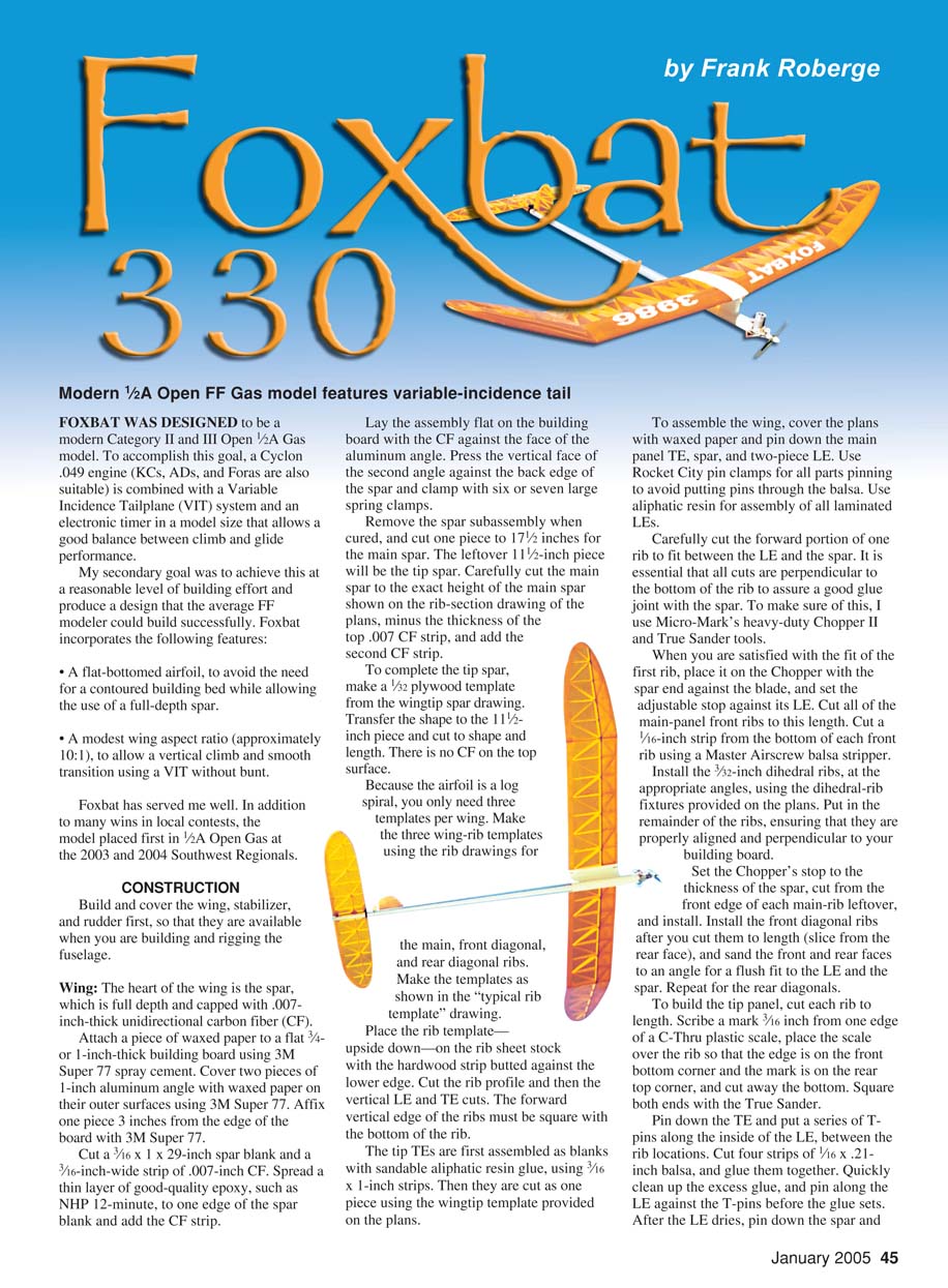
Mount the bladder assembly on the .078-inch-diameter skid, insert the skid into the engine mount, and install the engine.
Mount the flood-off bracket to the bottom of the right-hand engine-mounting lug. Install the timer (with appropriate launch switch) and the VIT assembly.
Mount the wing and stabilizer, and insert the engine assembly into the fuselage. Check the CG position and add weight to the nose or tail as required (nose weight can be put inside the bladder compartment). A CG between 54% and 59% of the main chord is acceptable; 56% is optimum.
When you are satisfied with the CG location, completely disassemble everything and sand the engine-offset angles into the front of the carbon forebody. Drill clearance holes on each side of the forebody for the fuel lines to exit.
Install the bladder-compartment bulkhead (1/16 balsa) and fuel-proof it. Mask off the tailboom and paint the forward section of the fuselage with Klass Kote two-part epoxy primer and paint, per the manufacturer's instructions, for a beautiful, fuelproof finish.
Rigging
Slide the rudder-adjust nuts onto the rudder stop post, and position them so that the rudder has no left offset and can move 15° to the right. Glue a .025-inch music-wire hook in the position shown. Install a 5/8-inch dental band between the hook and the rudder horn.
Rig the three VIT control lines. Stretch in the lines provides the force necessary to hold the surfaces firmly in position.
It's easiest to install the rudder line by feeding a piece of .015-inch music wire through the tube in the rear timer-mount face, then out the rear through the VIT cutout in the tailboom. Feed the rudder line through its hole in the tailboom, at the front of the rudder, and out the VIT cutout. Cyanoacrylate-glue the rudder line to the end of the music wire, and pull it forward through the timer-mount hole.
You install the DT and power lines in a similar manner. The only difference is that the forward portion is 20-pound monofilament and the rear 10 inches is 30-pound braided Dacron, to provide smooth action where the lines make a 90° turn around the 3/32-inch-diameter guide tubes. Route the lines through the VIT assembly (see the isometric drawing), remount the assembly, and complete the rigging.
Final Assembly and Checkout
Install the engine mount with DP-460, holding it in place with masking tape to make sure it is fully seated against the forebody at the proper offset angles. Redrill the fuel-line exit holes through the engine-mount skirt. Install the engine flood-off line as shown on the plans.
Adding a flood-off fitting to the Cyclon engine is straightforward. Fill the cast round emblem on the right side of the venturi with J.B. Weld epoxy. Insert a snugly fit wooden dowel fully into the venturi, and drill through the venturi wall and tap for a 2-56 thread. Remove the dowel and clean the area. Install a 2-56-size pressure fitting. Reassemble the model and make certain that all of the systems are functioning properly.
Spend some time running the systems repeatedly until you are satisfied that everything operates smoothly and reliably.
Flight-Testing
With the power and rudder lines disconnected, hand-glide the model from shoulder height, at glide speed, over the proverbial tall grass. You are looking for a light, floating glide with the beginnings of a wide right turn. Continue to adjust the rudder- and glide-adjust nuts until your model has a smooth glide.
Set the power-adjust screw so that there is a 3/32-inch gap between the glide-adjust nut and the upper surface of the stabilizer. Hook up the rudder and power lines.
Hand glide as before with a little more speed. You are looking for a fast glide that goes exactly where you point the model, with no tendency to float, nose over, or turn. Adjust the power screw and rudder nut until you are satisfied. At this point the model should be safe for its first powered flight.
Set the timer for a 2.0-second engine run, leave the glide/DT line disconnected from the timer (quick DT), and set the rudder and power lines for release 1.2 seconds after engine shutoff. With the engine running at full power, launch the model at an 80° angle. Make adjustments for any turning, looping, or nose-over tendencies, and continue with 2.0- to 3.0-second flights until the model is climbing safely up at 80° with a slight right turn and left roll.
Increase the engine run 2.0 seconds at a time, repeating and making adjustments until you have a 9.0-second climb at an 80° angle and a 270°–360° right-hand turn and left roll. If you see excess left roll or a flat arcing to the right with no roll, adjust the right main-panel wash-in with a sealing iron (more wash-in, more roll) before continuing.
Once the climb pattern is solid, it’s time to trim the transition and glide. Leave the 1.2-second delay on the rudder and power lines, and set the timer for a 30-second DT. Set the engine for a 9.0-second run and let 'er rip.
You are looking for a smooth right-hand transition from climb to glide. Depending on your engine’s power and your model’s weight (climb speed), the delay between the engine flood-off to power and rudder-line release may vary anywhere between 0.8 and 1.4 seconds for a smooth transition with no altitude loss.
When you are satisfied with the climb and transition, you can fine-tune the glide using the right-hand rudder-adjust nut and the glide-adjust nut for a fairly wide-open, slow, floating glide.
At this point you should be ready to go out and win a contest. Good thermals! MA
Frank Roberge 8057 E. Charter Oak Rd. Scottsdale AZ 85260
Transcribed from original scans by AI. Minor OCR errors may remain.

