
Free Flight: Duration
Harry Murphy 3824 Oakwood Blvd. Anderson, IN 46011
Self-Timer
The state-of-the-art FAI Power model comes equipped with a mechanical brain in the form of a five-function clockwork timer. This device serves as an onboard controller for such preset disciplines as fuel cutoff, bunt transition from power into glide mode, and dethermalizer. The timer also acts as a controller for autorudder and/or flapper control, if either or both are incorporated in the model.
Obviously, it takes many flights and many trips to the test-flying site to fine-tune all of the incorporated gadgetry to achieve optimum power, transition and glide in a given model. Oftentimes these flight sessions are lonesome affairs, with the persistent flier finding himself alone at the test site as he seeks the ultimate trim from his sophisticated flying machine.
The engine run is a crucial segment of Power model flight. Since modelers know that the maximum engine run possible results in the maximum altitude attainable, the difference between a full engine run as permitted by the rules and an overrun which would default an otherwise perfect flight can be mere fractions of a second.
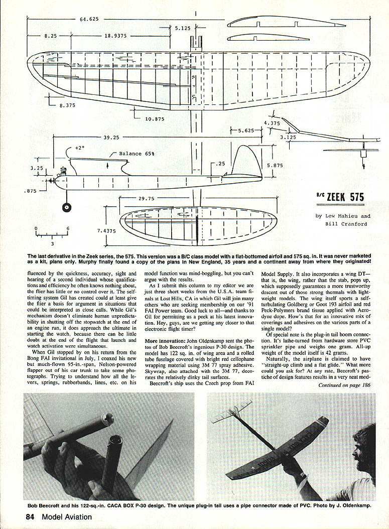
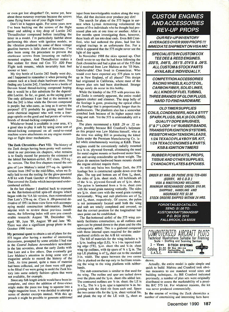
Fine-tuning engine runs has always been a problem when flying alone, since it's difficult to launch a model and start a stopwatch at the same instant. However, FAI Power enthusiast Gil Morris has dropped a self-timing innovation on us that may prove popular with our "lonesome flier" constituents.
As the accompanying photo depicts, Gil has needled his way into the miniature circuitry of a digital wristwatch and wired in a pressure-sensitive switch contained in a standard rubber thumb guard.
Wearing the altered chronograph on his launching arm, he dons the thumb guard and plugs the two contacts into the watch prior to each flight. The stopwatch function is set to zero as the model is gripped and readied for launch.
When the grip is released as the model is launched, the watch instantly records the launch and begins running. Gil closes his thumb and forefinger on the contained switch until the engine ceases running, when he shuts off the stopwatch by releasing his hold on the switch. What he sees on the watch face is the elapsed engine run. If it's an overrun, he can't blame the guy who's timing him, because he did the timing himself. Neato!
When you think about it, timing engine runs often leads to controversy because the human element is involved. Since the timing process is influenced by quickness, accuracy, sight, hearing and the second individual's qualifications, the flier often has little or no control over who times him. The self-timing system Gil has created could at least give the flier a basis for argument in situations that could be interpreted as close calls. Gil's mechanism doesn't eliminate human unpredictability, but shutting off the stopwatch at the end of the engine run does approach the ultimate. Starting the watch at launch is close because there's little doubt the end of the flight and the watch activation are simultaneous.
As this column is submitted just three short weeks before USA team finals at Lost Hills, CA, Gil will join others seeking membership on the '91 FAI Power team. Good luck to him, and thanks to Gil for permitting us a peek at his latest innovation.
Hey, guys, are we getting any closer to that electronic flight timer?
Bob Beecroft's P-30
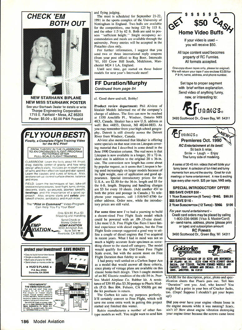
More innovation: John Oldenkamp sent photos of Bob Beecroft's ingenious P-30 design. The model has 122 sq. in. of wing area and a rolled-tube fuselage covered with bright red cellophane wrapping material using 3M 77 spray adhesive. Skywrap, also attached with 3M 77, decorates the relatively dinky tail surfaces.
Beecroft's ship uses the Czech prop from FAI Model Supply. It also incorporates a wing DT — the wing, rather than the stab, pops up, which supposedly guarantees a more trustworthy descent out of those strong thermals with lightweight models. The wing itself sports a self-ventilating Goldberg (or Goer) 193 airfoil and uses Pack-Polymers brand tissue applied with Aerodex dope. How's that for an innovative mix of coverings and adhesives on the various parts of a single model?
Of special note is the plug-in tail boom connector. It's tube-turned from hardware-store PVC sprinkler pipe and weighs one ounce. All-up weight of the model itself is 42 grams.
Naturally, the airplane is claimed to have "straight-up climb and a flat glide." What more could you ask for? At any rate, Beecroft's choice of design features results in a very neat model.
Well, good show-and-tell, Bobby!
Product Review Department
Phil Alvirez of Idealair Models informed me of the company's change of address. The firm can now be reached at 1350 Arncliffe Pl., Windsor, Ontario N8S 4K3, Canada. Idealair has a new U.S. address as well: Box 44853, Detroit, MI 48244-0853. As you may remember from your high school geography, Detroit is still directly across the Detroit River from Windsor, Canada.
Alvirez also mentioned that Idealair is offering some specials on their neat iron-on Litespan covering material that I described in some detail in the June 1990 Duration column. The new news is that Litespan is now available in a longer 20 x 72 in. sheet in addition to the original 20 x 36 in. size. The convenient new length has come about by popular request, as it seems Litespan is being used increasingly on larger models because of its light weight, ease of application and good appearance.
Special introductory prices for the U.S.A. are $2.50 for the 36-in. length and $5 for the 72-in. length. Shipping and handling charges are $3 for every 10 sheets. (Add another 45c to both the price and postage in Canada.) To telephone your requests, call 1-519-947-8790 for either address. Order now, while the introductory prices are still valid.
Free Flight Scale Project
For some time now I've had a yearning to build a decent-sized Free Flight Scale model which could be powered with an .09–.15-size diesel. Like most U.S. Free Flight Gas fliers I have limited experience with diesel engines, other than the occasional success we've had in the '50s and '60s in contests with engines that would run for a couple dozen seconds on the odd hand-started glow model. What I had in mind was not so much a highly accurate scale representation as something closer to the stand-off category. The model would qualify for the Old-Timer Free Flight Scale event, but with the accent more on Free Flight Duration than on total fidelity to the original.
I had pretty well settled on a Corben Ace as a model that would answer all the criteria, since plenty of vintage plans are available on this classic home-built design. Then I caught mention of an RC electric rendition of the old 54-in. Pearson Model Airplane Co. rubber kit. A reintroduction offer of $39.95 plus $3.50 postage from Pharis Modelers, P.O. Box 805, Folsom, CA 95630, got me a copy of the kit. The Corben kit suits my purposes perfectly. It'll certainly convert to Free Flight, which will save me some extra work in getting this project started and finished this winter.
Robin manufactures a number of other fun-type models as well.
Thread-locking Compounds — A Tip
Don't let mission-critical screws back out in flight. For some years now I've been backing out the screws of the flight timer and adding a tiny drop of Loctite 242 Threadlocker compound before installing the timer in a model. I'm particularly faithful about performing this chore with ignition models, as the vibration produced by some of these vintage gasoline burners is little short of ferocious. I've also been using the procedure to prevent the crankcase screws from loosening on radially mounted engines. And Threadlocker makes a fine sealant for those red Cox TD .020 Free Flight tank mounts, which invariably leak fuel sooner or later.
My tiny bottle of Loctite 242 finally went dry, and I happened to remember it when perusing the current rack at a local chain hardware store. Not finding any Loctite 242, I latched on to a bottle of Devcon brand thread-locking compound hoping that it would be a fair substitute for the dependable Loctite. So far, so good, as the saying goes! The only difference I can find at the moment is that the 242 is blue while the Devcon compound is purple; but who cares, as long as it serves the purpose?
Whichever brand is available in your area, it's a good idea to play it safe by using some sort of thread-locking compound on all metal-to-metal machine-screw attachments on any engine mountings or flight-timer mechanisms.
The Zeek Chronicles — Part VII
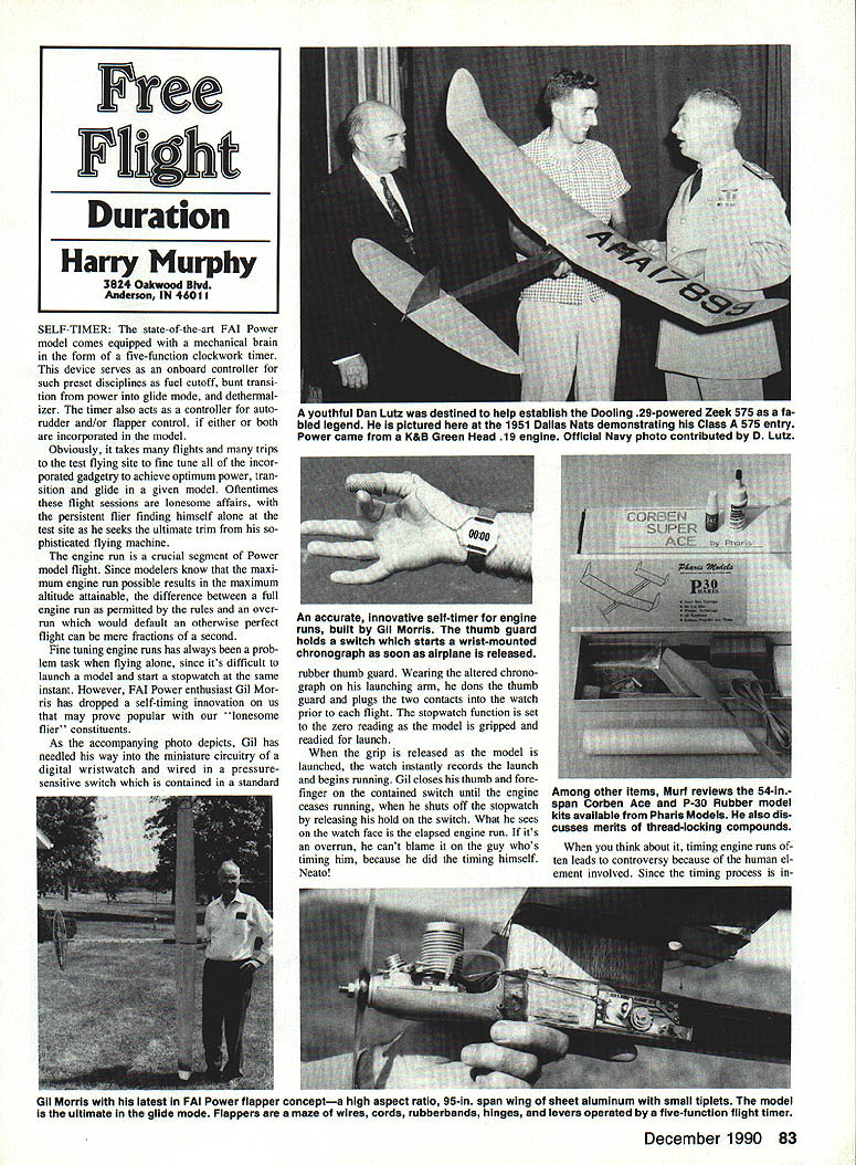
The history of the Zeek design having been pretty well summarized in our previous six chapters, what remains is to finally record for posterity the existence of the fabled flat-bottom airfoil, B/C class, 575-sq.-in. version. The first five chapters traced the origins of Lew Mahieu's initial 277-sq.-in. ignition version from 1947 to the mid‑fifties, when we finally laid to rest the tooling for the glow‑powered A/B kit with Frank Garcher of Midwest Models. That covered the Zeeks which incorporated undercambered airfoils.
In the last chapter I doubled back to expound on the flat‑bottom‑airfoil spin‑off designs which began with the 7/8 A kit version, then reintroduced Dan Lutz's 276‑sq.-in. Class A, 0‑powered derivative of 1951 in three‑view form with accompanying model construction information. Should anyone wish to receive those previous installments, the following index will save you considerable research: August '58, December '88, April '89, June '89, August '89 and June '90. There was also a significant group photo in the October 1990 issue.
My personal quest to obtain a set of plans for the 575 began after having a number of interesting discussions, prompted by some articles I had run in the Central Indiana Aeromodellers newsletter in the late seventies, about the early Zeeks with Dan Lutz and a few others. I solicited input from knowledgeable readers along the way, and that decision produced pay dirt.
The search for plans of the 575 began in earnest when Lyman Armstrong volunteered the names of five individuals who he thought had possessed plan sets at one time or another. After a few months spent investigating them, however, these leads all ran into dead ends. Even Bill Cranford, who had authored the plans, had lost his original tracings in an unfortunate fire. For a while it appeared that the 575 might never see the light of day again.
In November 1988 the skies opened up. Chet Orrill wrote to say that he had been following the Zeek chronicles and had a plan set of the 575 that he received from Lew Mahieu at the '53 Nats. Unbelievable! (Well, I lived in Connecticut. Who would ever have expected any 575 plans to turn up in New England, of all places?) This design had originated in California, where most of the known plan sets had been distributed. Strange things surely do occur in this hobby.
While the kinship of the 575 with previous Zeeks is certainly apparent, the entire model appears sleeker and slimmer. The deep belly of the fuselage is gone, producing the optical effect of a fuselage that is proportionately longer than its predecessors. The planform also has a somewhat stretched look because of its higher aspect‑ratio wing and stab. Yet the 575 is unmistakably still a Zeek.
The plans recommend a K&B .29 or .32 engine, possibly because Bill Cranford's helper on this project was Lew Mahieu himself, who at the time was aiding Bill in producing the kitted Zeeks under the Premium Manufacturing Co. These engines could be conveniently mounted to a 1/4‑in. plywood firewall, eliminating the need for metal engine mounts or hardwood motor bearers and saving considerable building time.
As with any balsa‑box fuselage Zeek, the 575 fuselage box is constructed upside down over the plan. The top and bottom are of firm 1/8‑in. sheet, the sides of 1/8‑in. sheet stock. All bulkheads aft of the 1/8‑in. plywood firewall are of 1/8‑in. sheet. The pylon is laminated from 1/8‑in. sheet with the wood grain running vertically. The wing and stab are conventional built‑up structures: the wing ribs are 1/16‑in. sheet, the LE is 1/4‑in. sheet tapered where required, and the TE is 1/8‑in. sheet. Space between the two center ribs is planed on the top only to facilitate retaining the wing to the wing platform with rubber bands.
The stab construction is similar to that used for the wing. The outline and spar are of the same basic stock used in the wing; the contoured outlines are 1/8‑in. sheet. The two center ribs are spaced to facilitate the rubber‑band wing retention and the skinning details follow conventional Zeek practice.
My copy of the 575 plans reproduces the original kitted drawings with the usual notes and suggested materials. The Zeek 575 as described offers a fine compromise between size, handling and performance; it flies smoothly and has excellent glide characteristics.
While Lew Mahieu single‑handedly conceptualized and designed the original Zeeks, he never had full responsibility for kitting any of the derivatives. This despite the fact that he worked for Air‑O and Premium when they were producing the commercial Zeek kits, and even worked for K&B when it produced his subsequent Kiwi design.
The original Zeek kits were the first to show a fuse‑operated pop‑up DT. They were also the first in which tilting the stab up on one side or the other would produce glide turn in the corresponding direction without noticeable effect on the power portion of the flight.
If nothing else, this series has re‑lit the candles to illuminate some heretofore fabled Zeeks which had yet to see the commercial print, and those responsible for their being have been given proper credit. That list includes the original 227‑sq.-in. 1947 ignition‑powered version, drawn by Stu Sittig; the Lutz‑produced '51 Class A .09 derivative; and the Cranford B/C 575. All were directly influenced by Lew Mahieu, though in each case the recorded plans were drawn by another individual. Obviously Lew Mahieu preferred work and innovation to standing still for the laurels he deserved.
Our hats are off to Lew Mahieu and all of his one‑time associates in the making of a Free Flight legend. One thing is certain: People may eventually fade away in our hobby, but Zeeks are forever.
Lastly, I am forever indebted to the many with whom I have had discussions, correspondence, and phone conversations over the past 10 years. Proper acknowledgment of their responsiveness and of the good things that have emerged from this colloquy would fill another chapter. In lieu of this I shall simply close with an alphabetical listing of names that are included in my six‑inch‑deep pile of correspondence accumulated over 10 years. Those individuals are: Lyman Armstrong, Bill Cranford, Ray Downs, Gerald Fowler, Russ Hansen, F.K. Heeb, Elmer Jordan, Dan Lutz, Lew Mahieu, Ed Mate, Chet Orrill, Russ Snyder, Bob Spink, Carl Stokes and Ed Tomer. My heartfelt thanks to all of you. If I've forgotten anyone, my most humble apology for the oversight.
Obviously, in 10 years of reliving Zeek designs and, in turn, their contribution to the growth in popularity of the Nostalgia Gas movement, I have acquired a considerable inventory of full‑size Zeek plans. Should anyone require information in this regard, a large SASE will get you a listing.
That's it! There ain't no more. Till next time, see you downwind!
Transcribed from original scans by AI. Minor OCR errors may remain.

