
Free Flight: Duration
Louis Joyner 4257 Old Leeds Road, Birmingham, AL 35213
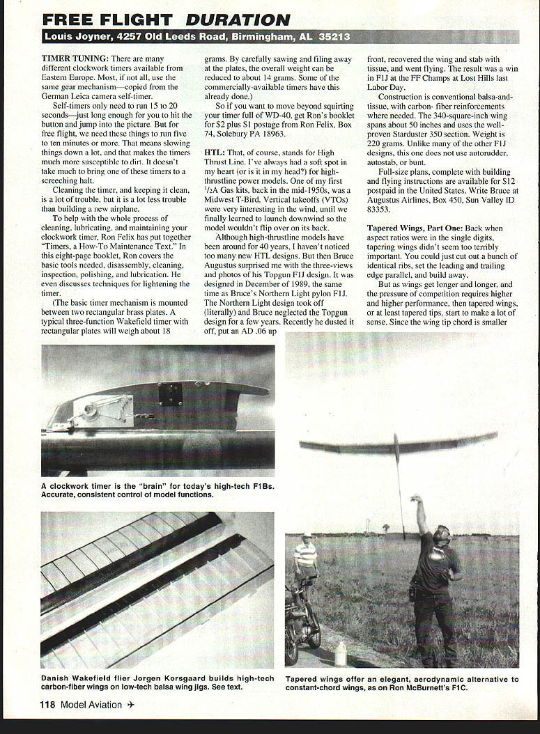
Timer Tuning
There are many different clockwork timers available from Eastern Europe. Most, if not all, use the same gear mechanism copied from the German Leica camera self-timer. Camera self-timers only need to run 15–20 seconds—just long enough for you to hit the button and jump into the picture. For free flight, however, we need timers to run five to ten minutes or more. Slowing the mechanism that much makes the timers much more susceptible to dirt; it doesn't take much to bring one to a screeching halt.
Cleaning the timer, and keeping it clean, is a lot of trouble, but it is a lot less trouble than building a new airplane. To help with cleaning, lubricating, and maintaining your clockwork timer, Ron Felix has put together Timers: a How-To/Maintenance text. In this eight-page booklet Ron covers:
- Basic tools needed
- Disassembly
- Cleaning
- Inspection
- Polishing
- Lubrication
- Techniques for lightening the timer
The basic timer mechanism is mounted between two rectangular brass plates. A typical three-function Wakefield timer will weigh about 18 grams. By carefully sawing and filing away at the plates, the overall weight can be reduced to about 14 grams. Some commercially available timers are already lightened.
If you want to move beyond squirting your timer full of WD-40, get Ron's booklet for $2 plus $1 postage from: Ron Felix, Box 74, Solebury, PA 18963
HTL
HTL stands for High Thrust Line. I've always had a soft spot in my heart (or is it in my head?) for high-thrust-line power models. One of my first 1/2A gas kits, back in the mid-1950s, was a Midwest T-Bird. Vertical takeoffs (VTOs) were very interesting in the wind, until I finally learned to launch downwind so the model wouldn't flip over on its back.
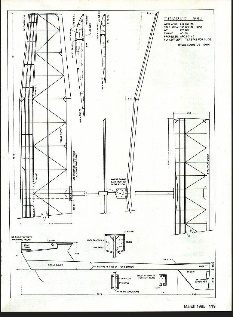
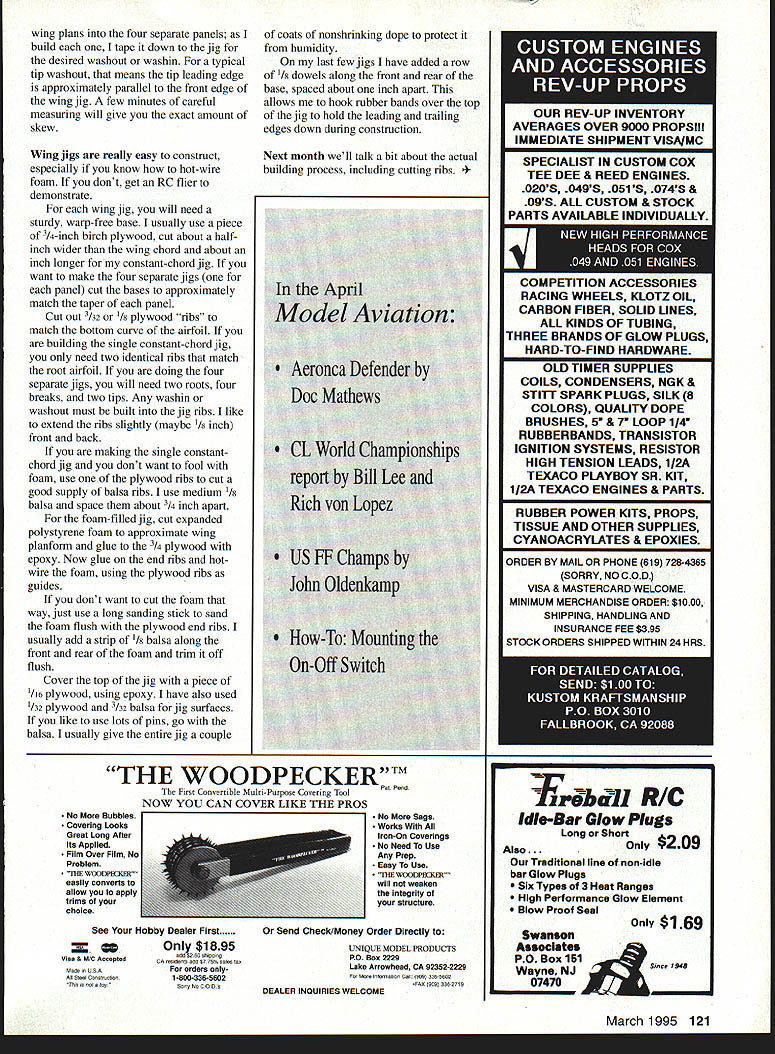
Although high-thrust-line models have been around for 40 years, I haven't noticed many new HTL designs. Then Bruce Augustus surprised me with three-views and photos of his Topgun F1J design. It was designed in December 1989, the same time as Bruce's Northern Light pylon F1J. The Northern Light design took off (literally) and Bruce neglected the Topgun design for a few years. Recently he dusted it off, put an AD .06 up front, recovered the wing and stab with tissue, and went flying. The result was a win in F1J at the FF Champs at Lost Hills last Labor Day.
Construction is conventional balsa-and-tissue, with carbon-fiber reinforcements where needed. The 340-square-inch wing spans about 50 inches and uses the well-proven Starduster 350 section. Weight is 220 grams. Unlike other F1J designs, this one does not use autorudder, autostab, or bunt.
Full-size plans, complete with building and flying instructions, are available for $12 postpaid in the United States. Write: Bruce Augustus Airlines, Box 450, Sun Valley, ID 83353
Tapered Wings, Part One
Back when aspect ratios were in the single digits, tapering wings didn't seem terribly important. You could just cut out a bunch of identical ribs, set the leading and trailing edges parallel, and build away.
As wings got longer and competition demanded higher performance, tapered wings—or at least tapered tips—started to make a lot of sense. Since the wing tip chord is smaller, the vortex at the tip should be less, reducing drag. Perhaps more importantly, the center of gravity of the wing half will be closer to the fuselage; tips will be lighter. Like a light tail, light tips make the model lively and more able to handle disturbances without stalling. The main drawback is they are harder to build.
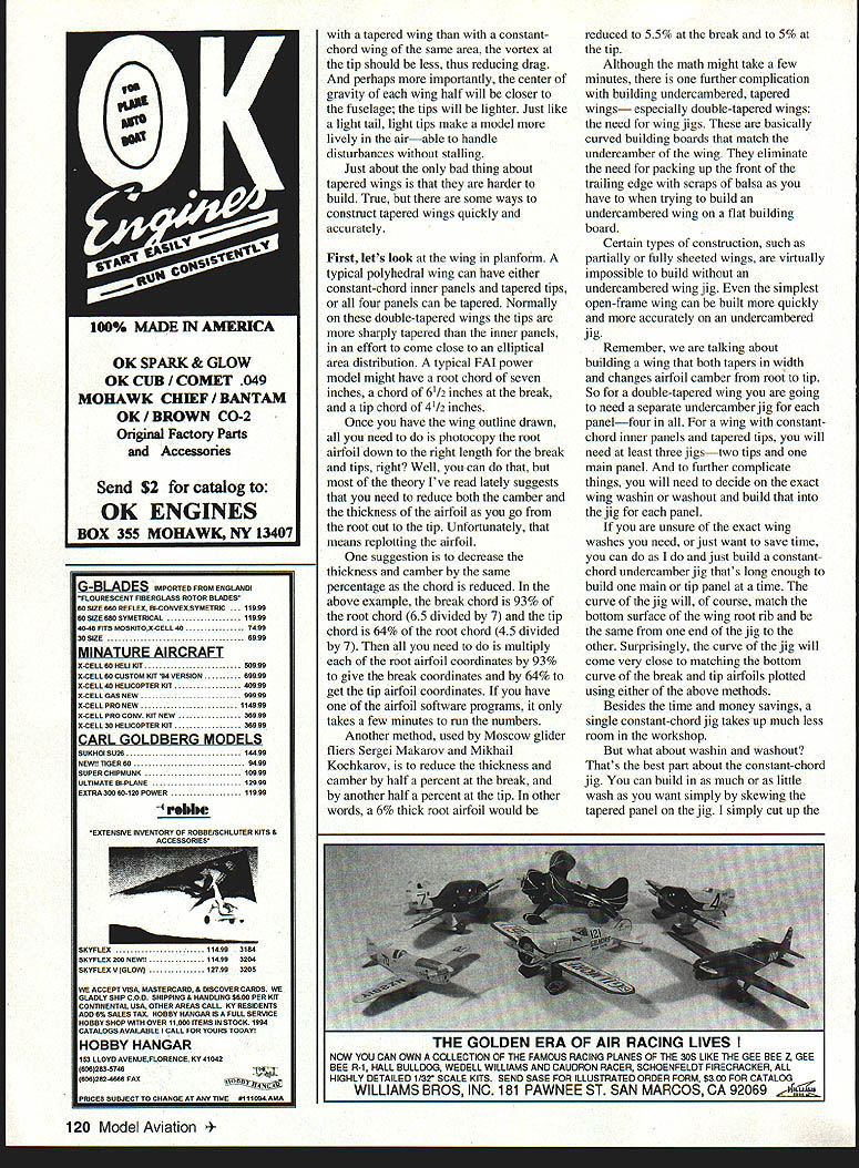
First, let's look at wing planform. A typical polyhedral wing can have either constant-chord panels or be broken into four separate panels. As I build each panel I tape it down to the jig for the desired washout or wash-in. For a typical tip washout, the tip leading edge is approximately parallel to the front edge of the wing jig. A few minutes of careful measuring will give you the exact amount of skew.
Wing jigs are easy to construct, especially if you know how to hot-wire foam. If you don't, ask an RC flier to demonstrate.
Basic jig construction steps:
- Prepare a sturdy, warp-free base. I usually use a piece of 3/4-inch birch plywood, cut about 1/2 inch wider than the wing chord and about 1 inch longer for a constant-chord jig. If you want four separate jigs (one for each panel), cut the bases to approximately match the taper of each panel.
- Cut out 3/32- or 1/8-inch plywood "ribs" to match the bottom curve of the airfoil. For a single constant-chord jig you only need two identical ribs that match the root airfoil. For four separate jigs you will need two roots, four breaks, and two tips. Build any wash-in or washout into the jig ribs. I like to extend the ribs slightly (about 1/8 inch) front and back.
- If making a single constant-chord jig and you don't want to work with foam, use one of the plywood ribs to cut a supply of balsa ribs. I use medium 1/8-inch balsa and space them about 3/4 inch apart.
- For a foam-filled jig, cut expanded polystyrene foam to approximate the wing planform and glue it to the 3/4 plywood base with epoxy. Glue on the end ribs and hot-wire the foam, using the plywood ribs as guides. If you don't want to hot-wire, sand the foam flush with the plywood end ribs with a long sanding stick. I usually add a strip of 1/8-inch balsa along the front and rear of the foam and trim it off flush.
- Cover the top of the jig with a piece of 1/16-inch plywood using epoxy. You can also use 1/32-inch plywood or 3/32-inch balsa for the jig surface; use balsa if you plan to use lots of pins. Give the entire jig a couple of coats of nonshrinking dope to protect it from humidity.
- Optional: add a row of 1/8-inch dowels along the front and rear of the base, spaced about 1 inch apart. This allows you to hook rubber bands over the top of the jig to hold the leading and trailing edges down during construction.
Next month we'll talk more about the actual building process, including cutting ribs.
Transcribed from original scans by AI. Minor OCR errors may remain.

