
FREE FLIGHT DURATION
Louis Joyner, 4221 Old Leeds Road, Birmingham AL 35213
Timers
The first gas model I built, back in the mid-1950s, was a 1/2A Zeek. Although I don't remember which of the Atwoods I used, I well remember the eyedropper tank.
Back then there weren't many options to limit engine run. Eyedroppers or coils of clear fuel tubing allowed at least some indication of the amount of fuel. You'd start the model, adjust the needle valve, refill the eyedropper, and watch until the level got down to a predetermined mark (often determined not by test runs but by "that looks about right"). Then you'd launch the model and hope the engine ran long enough to get the model up high enough, but not so long as to suffer an overrun.
It wasn't very accurate, but the engine run was only about 15 seconds hand-launched or 20 seconds ROG (rise off ground), so a few seconds less wasn't that bad.
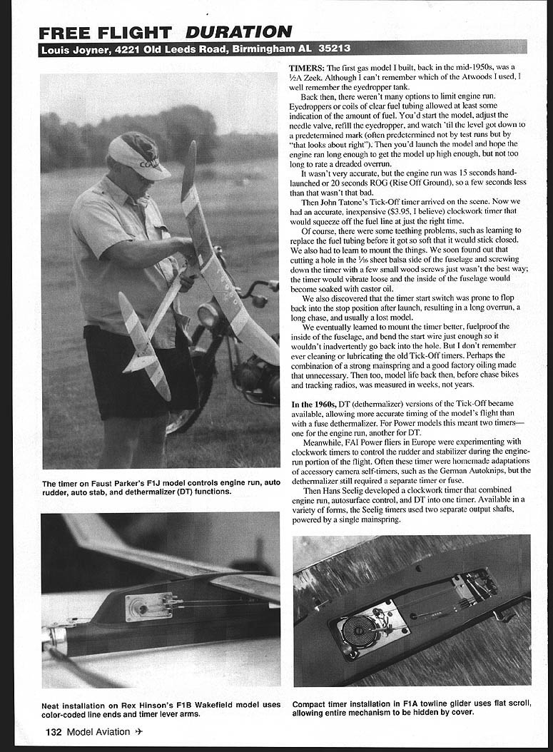
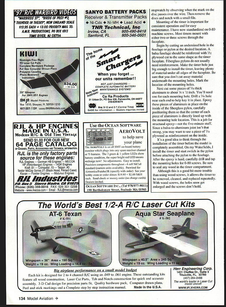
Then John Tatone's Tick-Off timer arrived. This accurate, inexpensive ($3.95, I believe) clockwork timer would squeeze off the fuel line at a set time. There were teething problems: fuel tubing would soften and stick closed, mounting by screwing through thin 1/16-inch balsa often failed, and the start switch was prone to flop back into the stop position after launch, causing overruns and lost models. We learned to mount the timers better, fuelproof the inside of the fuselage, and bend the start wire so it wouldn't inadvertently slip back. I never remember cleaning or lubricating the old Tick-Off timers—perhaps strong mainsprings and factory oiling helped—but model life then was measured in weeks, not years.
In the 1960s DT (dethermalizer) versions of the Tick-Off became available, allowing more accurate timing of the model's flight than with a fuse dethermalizer. For power models that often meant two timers — one for engine run and another for DT.
FAI Power fliers in Europe experimented with clockwork timers to control rudder and stabilizer during the engine-run portion of the flight. Often these were homemade adaptations of accessory camera self-timers, such as the German Autoknips, but the dethermalizer still required a separate timer or fuse.
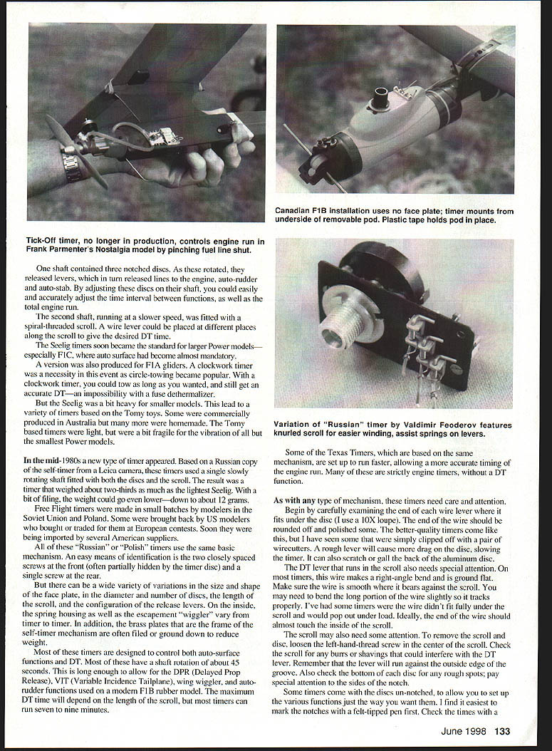
Hans Seelig developed a clockwork timer that combined engine run, auto-surface control, and DT into one unit. Seelig timers used two separate output shafts powered by a single mainspring and became standard on larger Power models, especially F1C, where auto-surface control became almost mandatory. A version was also produced for F1A gliders. With circle-towing becoming popular, a clockwork timer was a necessity — a circle-tow could tow as long as desired and still get an accurate DT, an impossibility with a fuse dethermalizer.
Seelig mechanism (and derivatives)
Many Seelig timers used a compact arrangement: one shaft contained three notched discs. As the shaft rotated, released levers turned and released lines for engine, auto-rudder and auto-stab. By adjusting the discs on the shaft one could easily and accurately adjust the time interval between functions as well as the total engine run.
A second, slower shaft was fitted with a spiral-threaded scroll; a wire lever could be placed at different positions along the scroll to set the desired DT time. Seelig timers were somewhat heavy for smaller models, which led to lighter designs based on Tomy toys (commercial and homemade). The Tomy-based timers were light but fragile and susceptible to vibration.
In the mid-1980s a new type of timer appeared based on a Russian copy of Leica camera self-timers. These used a single slowly rotating shaft fitted with both discs and the scroll, producing a timer about two-thirds the weight of the lightest Seelig; with filing, weights could go down to about 12 grams.
Russian and Polish timers
Free Flight timers were made in small batches by modelers in the Soviet Union and Poland. Some were brought back by U.S. modelers and later imported by American suppliers. These “Russian” or “Polish” timers use the same basic mechanism. An easy identification is two closely spaced screws near the front (often partially hidden by the timer disc) and a single screw at the rear. Variations exist in faceplate size and shape, number and diameter of discs, scroll length, and housing configuration. Inside, spring housings and escapement “wigglers” vary, and brass plates are often filed or ground to reduce weight.
Most of these timers are set up to control both auto-surface functions and DT. Typical shaft rotation is about 45 seconds—long enough for DPR (Delayed Prop Release), VIT (Variable Incidence Tailplane), wing wiggler, and auto-rudder functions on modern F1B rubber models. Maximum DT time depends on scroll length but is often seven to nine minutes. Some Texan-style timers based on the same mechanism run faster and are configured strictly as engine timers without DT.
Inspection and setup
- Carefully examine each wire lever end where it fits under a disc (use a 10X loupe). The end should be rounded and polished smooth. A rough or clipped-off end increases drag on the disc and can scratch or gall the back of an aluminum disc.
- The DT lever that runs in the scroll needs special attention. The wire typically makes a right-angle bend and is ground flat. Ensure the wire is smooth where it bears against the scroll and track it so it runs fully in the groove. Bend the long portion slightly if needed so it tracks properly; the lever end should almost touch the inside of the scroll. Some timers have the lever popping out under load if not seated fully.
- To inspect the scroll and disc, loosen the left-hand-thread screw in the center of the scroll. Check for burrs or shiny abrasions that could interfere with the DT lever. Check the bottom of each disc for rough spots and pay special attention to the disc notch.
- Some timers come with un-notched discs to allow custom setup. Mark notches with a felt-tip pen first, then check times with a stopwatch by observing when the mark on the disc passes over the wire. Remove the discs and mark the times on the face for repeatable setup.
Mounting
Mounting is important for consistent operation and easy maintenance. I standardize on 0-80 machine screws. Most timers mount with two or three screws through the faceplate.
- Cut an undersized hole in the fuselage or pylon at the desired location. Reinforce a balsa fuselage with 1/32 plywood cut to the same shape as the timer faceplate. Fiberglass pylons usually do not need reinforcement. Leave plenty of material under all edges of the faceplate and be sure not to cut away material under mounting holes.
- Mark mounting hole locations. Cut small pieces of 1/16-inch aluminum about 1/4 x 1/2 inch for each mounting hole. Drill a 1/16-inch hole near each end to help key them in place. Epoxy these aluminum pieces in position on the inside of the pylon, centering each over the mounting hole location. Use structural epoxy (not five-minute epoxy). For balsa joints add a piece of 1/16 plywood as reinforcement.
- After the epoxy hardens, carefully drill and tap the mounting holes for 0-80 screws. Seating plywood in the timer compartment is recommended.
This method allows the timer to be removed, cleaned, and replaced repeatedly. Wood screws eventually enlarge holes and fail to hold.
Once mounted, run lines to the various auto functions and color-code the lines and respective levers to avoid hookup mistakes (use paint or stripped telephone wire insulation). Make a start mark on the timer faceplate so you can set it to the same point every time—fine-point permanent marker works well. Practice hooking up all lines and starting the timer. Adjust function times by loosening the screw in the scroll (remember it is left-hand thread) and rotating the discs slightly; adjust DT by moving the lever to different slots and possibly rotating the scroll.
Cleaning and lubrication
Clean a brand-new timer before use and develop a habit of cleaning frequently between flying sessions. Dirty timers can have oil, dirt, balsa dust, and debris that prevent proper operation.
- Cleaning: Use aerosol brake cleaner outside (avoid skin contact), or a safer but flammable alternative such as Coleman lantern fuel. Dunk the timer with tweezers in a small jar of cleaner, pull it out, and let it air-dry on a clean sheet of typing paper (not a paper towel). If needed, carefully blow-dry with compressed air.
- Lubrication: Use a good synthetic oil such as Dukie's Timer Oil (available from Doug Galbreath) or Labelle oil (found at hobby shops that sell model-railroad supplies). Never use WD-40 or household oil. Lubricate only the pivot ends of each gear, not the gear teeth—too much oil attracts dirt. Use a piece of fine music wire as an oiler. The spring also needs lubrication.
- Access: Some timers have a slot in the cover for oiling; others require removing the cover (sometimes by prying). The Andrukovich timer has a slip-on, rimmed cover that is easy to remove and replace. Never wind the timer with the cover off.
- After cleaning and oiling, run the timer a few times and listen to its sound so you recognize normal operation. A dirty timer runs erratically and will sound different; check with a stopwatch if in doubt.
Sources:
- Doug Galbreath, 3408 Topsail Pl., Davis CA 95616 (Seelig timers, oil)
- Starline International, 6146 E. Cactus Wren Rd., Scottsdale AZ 85253 (Andrukovich and Fedorov timers)
- Hank Nystrom, 3317 Pine Timbers Dr., Johnson City TN 37604 (Texas Timers)
- Small Parts Inc., 13980 N.W. 58th Court, Box 4650, Miami Lakes FL 33014-0650 (0-80 screws and taps)
Transcribed from original scans by AI. Minor OCR errors may remain.

