
FREE FLIGHT DURATION
Louis Joyner, 4221 Old Leeds Rd., Birmingham AL 35213
LOCKED UP POWER
With all of the proposals being discussed for a new Slow Open Power event (SLOP), it might be useful to take a look at some of the ways that a power model can be controlled without the use of timer-actuated auto surfaces.
First, a quick refresher on the basic problem. Lift increases as a model goes faster. Lift is generally good, so wouldn't more lift be better? Not if it causes the model to loop.
The tendency of a model to loop (or at least nose up excessively) as its speed increases can be counteracted in several ways. The familiar tight spiral is, in effect, a sideways loop. It can keep the model from looping but it is not the most efficient way to adjust a model for maximum climb.
Another way to control the looping tendency is to decrease the decalage (the angular difference between wing and stabilizer). A popular trim from the 1950s used both wing and stab set at the same positive angle, effectively giving zero decalage. Often the right main wing panel was washed in (leading edge up) to give some slight amount of decalage.
This reduced decalage took care of the looping problem, but often required the center of gravity (CG) to be located at, or even behind, the wing trailing edge for the glide. (The CG location has less effect during the climb than during the glide.) If you have flown hand-launched gliders with a zero-zero wing–stab setting, then you know what can happen: straight up, straight down. It could, and often did, happen with those zero-zero, 100% CG gas models such as the Civy Boy and the early Satellites.
Some compromise trims eventually developed, with a small amount of decalage and a slightly more-forward CG (about 75% chord) combined to give a more open spiral climb. Designers also learned that the area and airfoil used for the stab were important. The idea was to have the stab lift increase proportionally with the wing lift increase to control the looping tendency.
The development of reliable clockwork timers eventually led to the use of auto surfaces. The auto stab, also called Variable Incidence Tailplane (VIT), and the auto rudder (AR) can be set for the optimum climb during the engine run, then released to predetermined glide settings at the end of the engine run. This allowed the model to use a smaller stabilizer (important in events where total area is limited) and a more-forward CG.
Since climb and glide could be adjusted independently, optimizing each became easier. With the addition of bunt to give a better transition from climb to glide, the auto-surface-equipped model has become the dominant type for F1C, F1J, and the open AMA Power events.
But some people feel that only the simpler, locked-up models are true Free Flight, and decry the increased complexity of the auto-surface model. Some are suggesting a separate event for power models without auto surfaces as a way to attract more people to the Power events. Others feel that the auto-surface models are more complicated to build but are easier to trim. Almost all agree that the auto-surface models hold the performance edge.
A few people are looking at new ways to design and adjust a power model, aiming for the simplicity of a locked-up model with the higher performance of an auto-surface model: a Slow Open Power model that could compete with Open Power. Perhaps "new" is not the best word — a look through the Zaic Year Books from the 1950s and 1960s shows many of these ideas aren't recent.
Keith Hoover and Very High Thrust Line (VHTL)
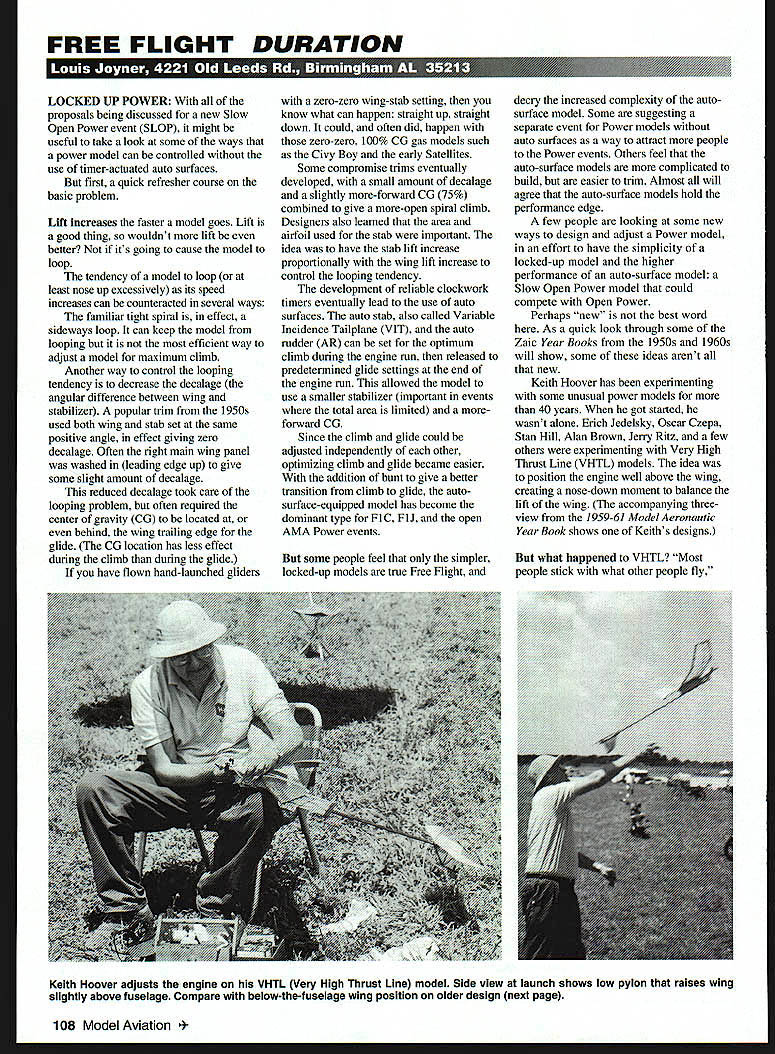
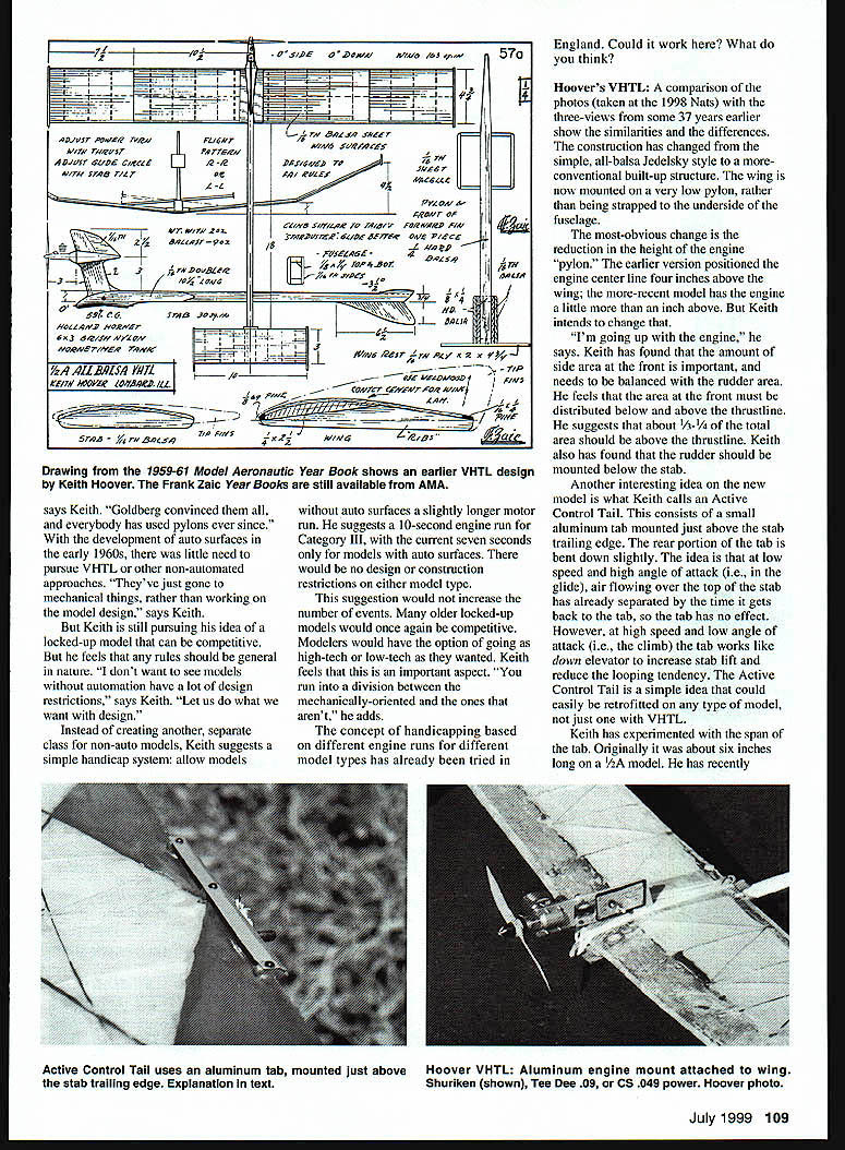
Keith Hoover has been experimenting with unusual power models for more than 40 years. When he got started, he wasn't alone. Erich Jedelsky, Oscar Czepa, Stan Hill, Alan Brown, Jerry Ritz, and a few others experimented with Very High Thrust Line (VHTL) models. The idea was to position the engine well above the wing, creating a nose-down moment to balance the wing lift. The accompanying three-view from the 1959–61 Model Aeronautic Year Book shows one of Keith's designs.
"But what happened to VHTL? Most people stick with what other people fly," says Keith. "Goldberg convinced them all, and everybody has used pylons ever since." With the development of auto surfaces in the early 1960s, there was little need to pursue VHTL or other non-automated approaches. "They've just gone on to mechanical things, rather than working on the model design," Keith adds.
Keith is still pursuing his idea of a locked-up model that can be competitive, but he feels any rules should be general in nature. "I don't want to see models without automation have a lot of design restrictions," he says. "Let us do what we want with design."
Instead of creating another separate class for non-auto models, Keith suggests a simple handicap system: allow models without auto surfaces a slightly longer motor run. He suggests a 10-second engine run for Category III, with the current seven seconds only for models with auto surfaces. There would be no design or construction restrictions on either model type.
This suggestion would not increase the number of events. Many older locked-up models would once again be competitive. Modelers would have the option of going as high-tech or low-tech as they wanted. Keith feels this is important. "You run into a division between the mechanically-oriented and the ones that aren't," he adds.
The concept of handicapping based on different engine runs for different model types has already been tried in England. Could it work here? What do you think?
Hoover's VHTL — recent changes
A comparison of photos (taken at the 1998 Nats) with the three-views from some 37 years earlier shows the similarities and differences. Construction has changed from the simple, all-balsa Jedelsky style to a more conventional built-up structure. The wing is now mounted on a very low pylon, rather than being strapped to the underside of the fuselage.
The most obvious change is the reduction in the height of the engine pylon. The earlier version positioned the engine centerline four inches above the wing; the more recent model has the engine a little more than an inch above. But Keith intends to change that. "I'm going up with the engine," he says.
Keith has found that the amount of side area at the front is important and needs to be balanced with the rudder area. He feels that the area at the front must be distributed both below and above the thrustline. He suggests that about one-quarter to one-third of the total side area should be above the thrustline. Keith has also found that the rudder should be mounted below the stab.
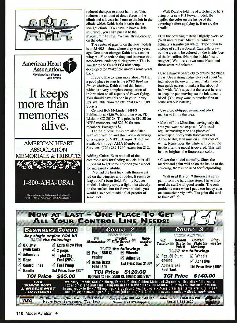
Another interesting idea on the new model is what Keith calls an Active Control Tail. This consists of a small aluminum tab mounted just above the stab trailing edge. The rear portion of the tab is bent down slightly. The idea is that at low speed and high angle of attack (i.e., in the glide), air flowing over the top of the tab has already separated by the time it gets back to the stab, so the tab has no effect. However, at high speed and low angle of attack (i.e., the climb), the tab works like down elevator to increase stab lift and reduce the looping tendency. The Active Control Tail is a simple idea that could easily be retrofitted on any type of model, not just one with VHTL.
Keith has experimented with the span of the tab. Originally it was about six inches long on a 1/2A model. He has recently reduced the span to about half that. This reduces the amount of down force in the climb and allows a full turn to the left in the climb, which Keith feels is safer than a straight climb. "You have to have a little insurance; you can't push it to the maximum," he says. "We are flying enough on the edge."
The center of gravity on the new models is at about 55–60% — roughly where they were years ago. One other change: Keith now sets the wing at -2° to reduce drag and increase the nose-down tendency during power. This is similar to the French PGI trim setup developed for Wakefield models some years back.
Further information and resources
If you'd like to learn more about VHTL, a good place to start is the NFFS Book on Power Models. Keith edited this book; it is a very complete compilation of information on all aspects of power flying. It's available from the National Free Flight Society.
Contact:
- Bob McLinden, NFFS Publications, 8256 W. Morraine Ave. #D, Littleton CO 80128.
- Price: $19.50 for NFFS members, $21.50 for non-members. Postage $4.
The Zaic Year Books are also filled with information and three-view drawings on a variety of VHTL designs. These are available through AMA Membership Services: (765) 287-1256, ext. 212.
Adding Color
Even with all of the electronic aids for finding models, it is still important to get some color on your model for increased visibility.
I've had the best luck with fluorescent red on the wingtips and rudder. It seems to leap out of a bean field. For my rubber models, I simply spray a light mist directly on the surface; but for power models you would also need to add a fuel-proofer of some sort.
Walt Rozelle told me of a technique he's using on a new F1J power model. He applies the color on the inside of the covering before applying it. Here are the details:
- Cut the covering material slightly oversize. (Walt uses "clear" Micafilm, which is actually a translucent white.) Tape it down to a piece of stiff cardboard. Carefully draw out the areas to be colored on the inside face of the Micafilm. (Note: the inside face is rougher.) Walt uses a two-tone, black-and-fluorescent-red scheme.
- Use a narrow Sharpie to outline the black areas. Use a straightedge elevated about 1/16 inch above the covering and make three or four quick passes to make a line about 1/8 inch wide. Walt says the secret is to keep the pen moving so the ink doesn't bleed. (You may want to practice first on some scrap Micafilm.)
- Use a broad-tipped permanent black marker to fill in the area.
- Mask off the Micafilm, leaving only the area you want red exposed. Walt used regular masking tape and pieces of newspaper. Spray with fluorescent red. Allow to dry, then mist on a light coat of white. Remember, the white will be on the inside after the model is covered; this will help brighten the fluorescent color.
- Cover the model normally. Since the marker and paint are on the inside of the covering, there is no need for fuelproofing.
Walt used Krylon fluorescent spray paint from the hardware store. I have also used it with good results. The only problems I encountered were when I applied too-heavy coats on some clear Mylar; the paint did tend to flake off.
Transcribed from original scans by AI. Minor OCR errors may remain.

