
Free Flight: Duration
Bob Meuser
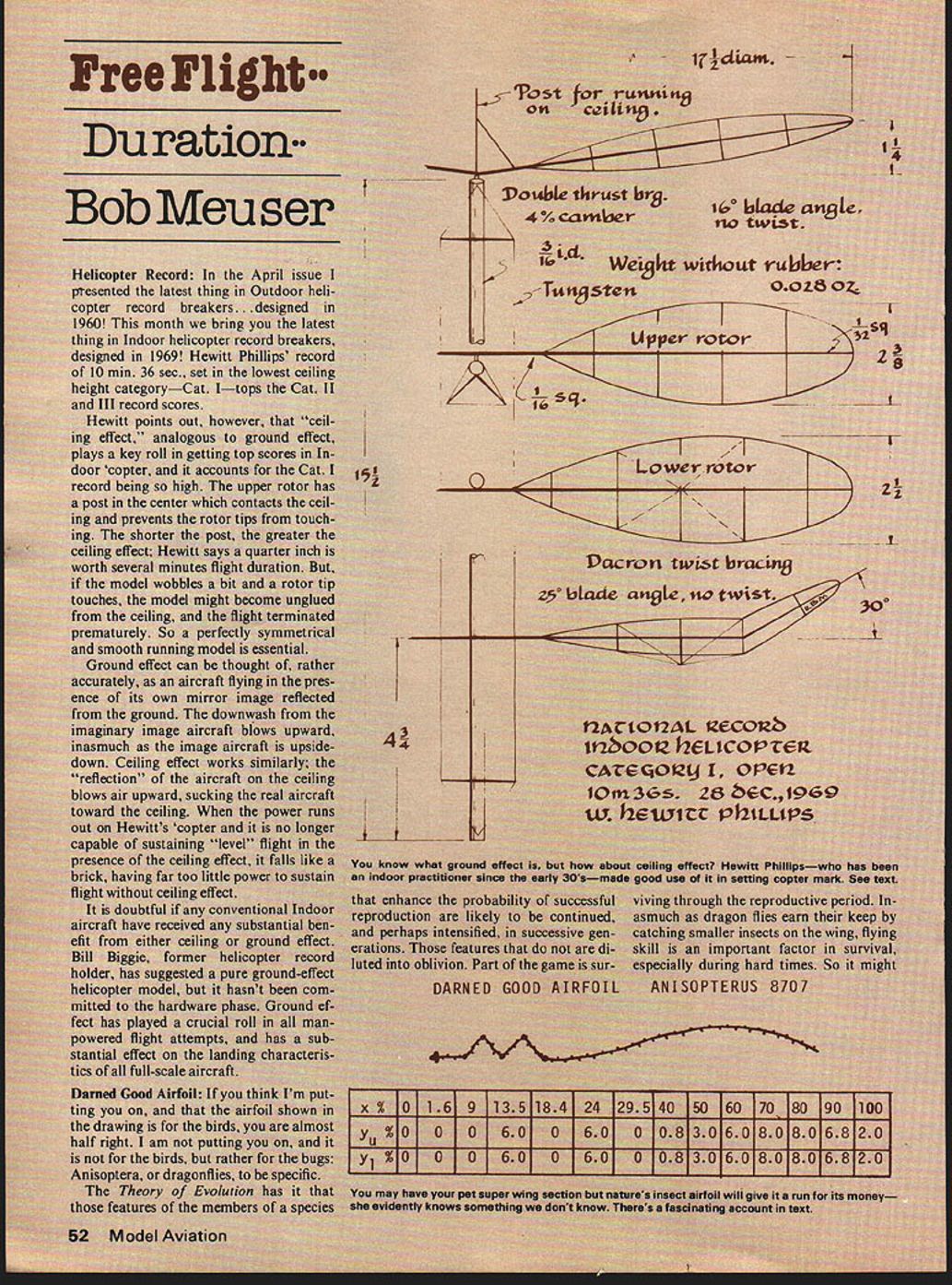
Helicopter Record: In the April issue I presented the latest thing in Outdoor helicopter record breakers ... designed in 1960! This month we bring you the latest thing in Indoor helicopter record breakers, designed in 1969! Hewitt Phillips' record of 10 min. 36 sec., set in the lowest ceiling height category—Cat. I—tops the Cat. II and III record scores.
Hewitt points out, however, that "ceiling effect," analogous to ground effect, plays a key role in getting top scores in Indoor 'copter, and it accounts for the Cat. I record being so high. The upper rotor has a post in the center which contacts the ceiling and prevents the rotor tips from touching. The shorter the post, the greater the ceiling effect; Hewitt says a quarter inch is worth several minutes flight duration. But if the model wobbles a bit and a rotor tip touches, the model might become unglued from the ceiling, and the flight terminated prematurely. So a perfectly symmetrical and smooth running model is essential.
Ground effect can be thought of, rather accurately, as an aircraft flying in the presence of its own mirror image reflected from the ground. The downwash from the imaginary image aircraft blows upward, inasmuch as the image aircraft is upside-down. Ceiling effect works similarly; the "reflection" of the aircraft on the ceiling blows air upward, sucking the real aircraft toward the ceiling. When the power runs out on Hewitt's 'copter and it is no longer capable of sustaining "level" flight in the presence of the ceiling effect, it falls like a brick, having far too little power to sustain flight without ceiling effect.
It is doubtful if any conventional Indoor aircraft have received any substantial benefit from either ceiling or ground effect. Bill Biggie, former helicopter record holder, has suggested a pure ground-effect helicopter model, but it hasn't been committed to the hardware phase. Ground effect has played a crucial role in all man-powered flight attempts, and has a substantial effect on the landing characteristics of all full-scale aircraft.
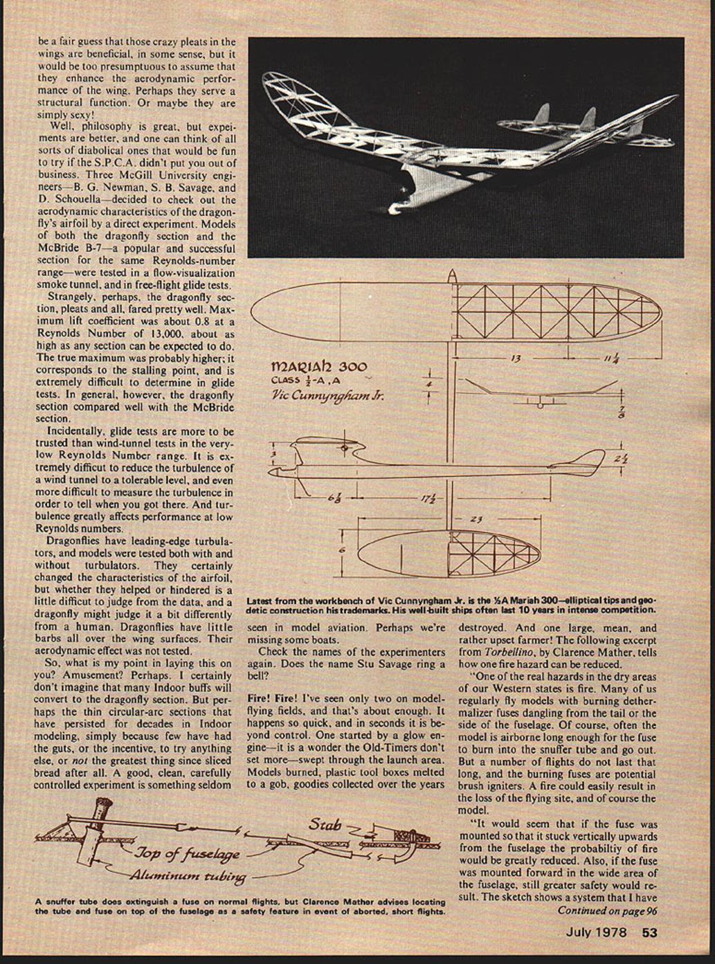
Darned Good Airfoil: If you think I'm putting you on, and that the airfoil shown in the drawing is for the birds, you are almost half right. I am not putting you on, and it is not for the birds, but rather for the bugs: Anisoptera, or dragonflies, to be specific.
The Theory of Evolution has it that those features of the members of a species that enhance the probability of successful reproduction are likely to be continued, and perhaps intensified, in successive generations. Those features that do not are diluted into oblivion. Part of the game is sur-
viving through the reproductive period. Inasmuch as dragon flies earn their keep by catching smaller insects on the wing, flying skill is an important factor in survival, especially during hard times. So it might be a fair guess that those crazy pleats in the wings are beneficial, in some sense, but it would be too presumptuous to assume that they enhance the aerodynamic performance of the wing. Perhaps they serve a structural function. Or maybe they are simply sexy!
Well, philosophy is great, but experiments are better, and one can think of all sorts of diabolical ones that would be fun to try if the S.P.C.A. didn't put you out of business. Three McGill University engineers — B. G. Newman, S. B. Savage, and D. Schouella — decided to check out the aerodynamic characteristics of the dragonfly's airfoil by a direct experiment. Models of both the dragonfly section and the McBride B-7 — a popular and successful section for the same Reynolds-number range — were tested in a flow-visualization smoke tunnel, and in free-flight glide tests.
Strangely, perhaps, the dragonfly section, pleats and all, fared pretty well. Maximum lift coefficient was about 0.8 at a Reynolds Number of 13,000, about as high as any section can be expected to do. The true maximum was probably higher; it corresponds to the stalling point, and is extremely difficult to determine in glide tests. In general, however, the dragonfly section compared well with the McBride section.
Incidentally, glide tests are more to be trusted than wind-tunnel tests in the very-low Reynolds Number range. It is extremely difficult to reduce the turbulence of a wind tunnel to a tolerable level, and even more difficult to measure the turbulence in order to tell when you got there. And turbulence greatly affects performance at low Reynolds numbers.
Dragonflies have leading-edge turbulators, and models were tested both with and without turbulators. They certainly changed the characteristics of the airfoil, but whether they helped or hindered is a little difficult to judge from the data, and a dragonfly might judge it a bit differently from a human. Dragonflies have little barbs all over the wing surfaces. Their aerodynamic effect was not tested.
So, what is my point in laying this on you? Amusement? Perhaps. I certainly don't imagine that many Indoor buffs will convert to the dragonfly section. But perhaps the thin circular-arc sections that have persisted for decades in Indoor modeling, simply because few have had the guts, or the incentive, to try anything else, or not the greatest thing since sliced bread after all. A good, clean, carefully controlled experiment is something seldom seen in model aviation. Perhaps we're missing some boats.
Check the names of the experimenters again. Does the name Stu Savage ring a bell?
Fire! Fire! I've seen only two on model-flying fields, and that's about enough. It happens so quick, and in seconds it is beyond control. One started by a glow engine — it is a wonder the Old-Timers don't set more — swept through the launch area. Models burned, plastic tool boxes melted to a gob, goodies collected over the years destroyed. And one large, mean, and rather upset farmer! The following excerpt from Torellino, by Clarence Mather, tells how one fire hazard can be reduced.
"One of the real hazards in the dry areas of our Western states is fire. Many of us regularly fly models with burning dethermalizer fuses dangling from the tail or the side of the fuselage. Of course, often the model is airborne long enough for the fuse to burn into the snuffer tube and go out. But a number of flights do not last that long, and the burning fuses are potential brush igniters. A fire could easily result in the loss of the flying site, and of course the model.
"It would seem that if the fuse was mounted so that it stuck vertically upwards from the fuselage the probability of fire would be greatly reduced. Also, if the fuse was mounted forward in the wide area of the fuselage, still greater safety would result. The sketch shows a system that I have"
FF Duration/Meuser
used on several models. An added feature is that the fuse is easy to light and to check, compared to the usual tail mount.
"I use aluminum tubing for the curved parts of the line path but plastic tubing could be used. Metal tubing will easily kink if bent sharply. I use the end of a finger or thumb as a form and bend slowly and carefully. A radius of one inch or less can be achieved by this method in 3/32 aluminum tubing. Metal tubes should then be flared out a bit at each end so that the line will not be cut. Twenty-pound test Dacron line works well for the line. Other sizes and types can be used. The front tube must be placed far enough rearward so that the stab will pop up to the desired angle. Check before mounting. The front hook will catch in the tube and act as a limiter. I bend the hooks out of pins, and they are plenty strong enough for a 1/4A gas model. A piece of 1/32 ply glued around the stab hole adds needed strength at that point. The rear wire will slide through the hole in the stab when placed parallel with the string. The sketch shows a typical set-up."
On a large model, a tail-mounted fuse that is beyond convenient reach of the flier, makes launching a two man job. On small, light models, the CG shift due to the burning fuse can change the glide pattern significantly. Even aside from the fire hazard, a tail-mounted fuse makes little sense. Clarence's idea of mounting the fuse on top seems like a winner.
However, for internal dethermalizer strings, plastic tubing, running clear from inlet to outlet, is often preferred over aluminum tubing. If the original string gets pulled out, it can be easily replaced. Twenty-pound woven Dacron or Nylon line can be pushed through from one end if the bends are gentle, and monofilament line can be pushed through a series of severe bends. On extremely lightweight models, where the weight of the plastic tubing might be a factor, an external DT string seems like the best bet.
Plastic tubing, selected for the purpose and well proved, can be obtained from NFFS Supplies, 9525 Achates Ct., Sacramento, CA 95826; send a S.A.S.E. for price list.
Top This One:
The following incident which will undoubtedly be nominated for the Best Grandstand Act of 1978, took place at the recent Max-Men F.A.I. An- Annual at Taft.
While Gary Medley was towing his A-2 towline glider for an attempt at a 14 max, the line slipped out of his hand, and the model took off downwind in good air with the line still attached. Thinking better of chasing it on foot, Gary ran back and got his motorcycle for the chase. When the model got low enough he abandoned the cycle, grabbed the towline, towed the model back to the field on foot, launched, and maxed.
Sandwiched between stormy weekends, this all-F.A.I. annual meet was blessed with two days of excellent flying weather. Most of the Southern California regulars were there, and there was a good representation from Northern Cal too. Competitors came from Michigan, Colorado, and Oklahoma too. And Peter Alnutt and his wife were there from Canada, as were Peter's parents from England. Five of the 14 entrants in A-2 Glider maxed out, and Bob Isaacson won with 14 maxes. There were two max-outs in both Wakefield and Power, with top honors finally going to Bob Piserchio and Roger Simpson. Among the five top fliers in the three events were five previous U.S. Team members plus an ex-World Champion. Quite a meet!
Official Manhattan Formula Rules: At long last, perhaps the rules for this event are nailed down. Until now, every published version differed slightly from every other published version. The rules published here are based on, but are not identical to the many versions published by the M.I.A.M.A. club, and they are also considerably different from Ed Whitten's original rules of a decade ago. These are the rules under which the event will be flown by active New York group. There will undoubtedly be local variations.
- Airframe weight, less rubber: 4 grams minimum.
- Overall length, measured from front of prop bearing: 20" maximum.
- Fuselage: (a) Must support and enclose a single rubber motor. No motor sticks. (b) Must include or exceed a box 2½" x 4" x 2". (c) Must have a windshield of 2 sq. in. minimum area, plus a window on each side of 1 sq. in. minimum area, covered with cellophane or similar transparent material.
- Prop: All wood, direct drive, fixed pitch.
- Wing: Monoplane with maximum projected span of 20' and maximum chord of 4". Wood bracing allowed.
- Stab: Monoplane stab with maximum projected span of 8" and maximum chord of 3½". Wood bracing allowed.
- Landing gear: Rigid and fixed with at least two wheels of 1" minimum diameter. Must be able to support model.
- Covering: Except for windshield and windows, only paper (including condenser paper) allowed. No film or Microlite.
- Flying: All flights at least two-point R.O.G. Best single flight counts. Unlimited number of official flights.
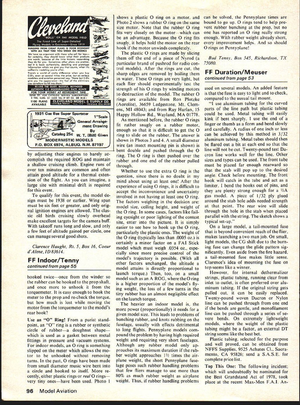
MARIAH 300: Latest from the well-worn workbench of Vic Cunningham, Jr. is this 300-square-incher intended for competition in Classes ½ A and A. Similar to Vic's Sirocco, published in Flying Models three years ago, Vic says the Mariah 300 is "...much better, and features three rudders, following the old Fast Richard concept that if one is good, two is better. Three should be just about right."
Many of Vic's models have more parts, and require greater building time, than more typical designs. Those geodetic ribs do take a little time to get right, but a wing built that way is unlikely to warp under even the most severe conditions. The wing on one of Vic's recent A-2 models has over 300 parts. Compare that with a typical Nordic A-2 glider which has about three times as many. Regarding A-2 wings, Bob Hatcher, who claims he hates to build models, recently remarked that "the wing looks as if it is ready to cover, and then you realize that you still have 200 parts to go." Vic regards the complexity as his "therapeutic exercise at the end of a working day."
Built during the winter, the Mariah has yet to experience the rigors of competition. But if history repeats, we'll probably still be hearing about it in 1988.
Bob Meuser, 4200 Gregory St., Oakland, CA 94619.
Transcribed from original scans by AI. Minor OCR errors may remain.

