
Free Flight: Duration
Jerry Barnette
Editor's Note: Jerry Barnette, who wrote this and last month's "Duration" column, is filling in temporarily for Bob Meuser.
Mr. Ed
For a model to be called Mr. Ed it probably was designed by a talking horse or someone named Edward. The "Mr. Ed" moniker was actually coined by Bob Sifleet. Ed Hopper's Nordic designs are referred to as Hoppers; his Wakefield design is called either Ed's Wakefield or Hopper's Wakefield — see the problem. Name problems aside, Mr. Ed is an excellent design.
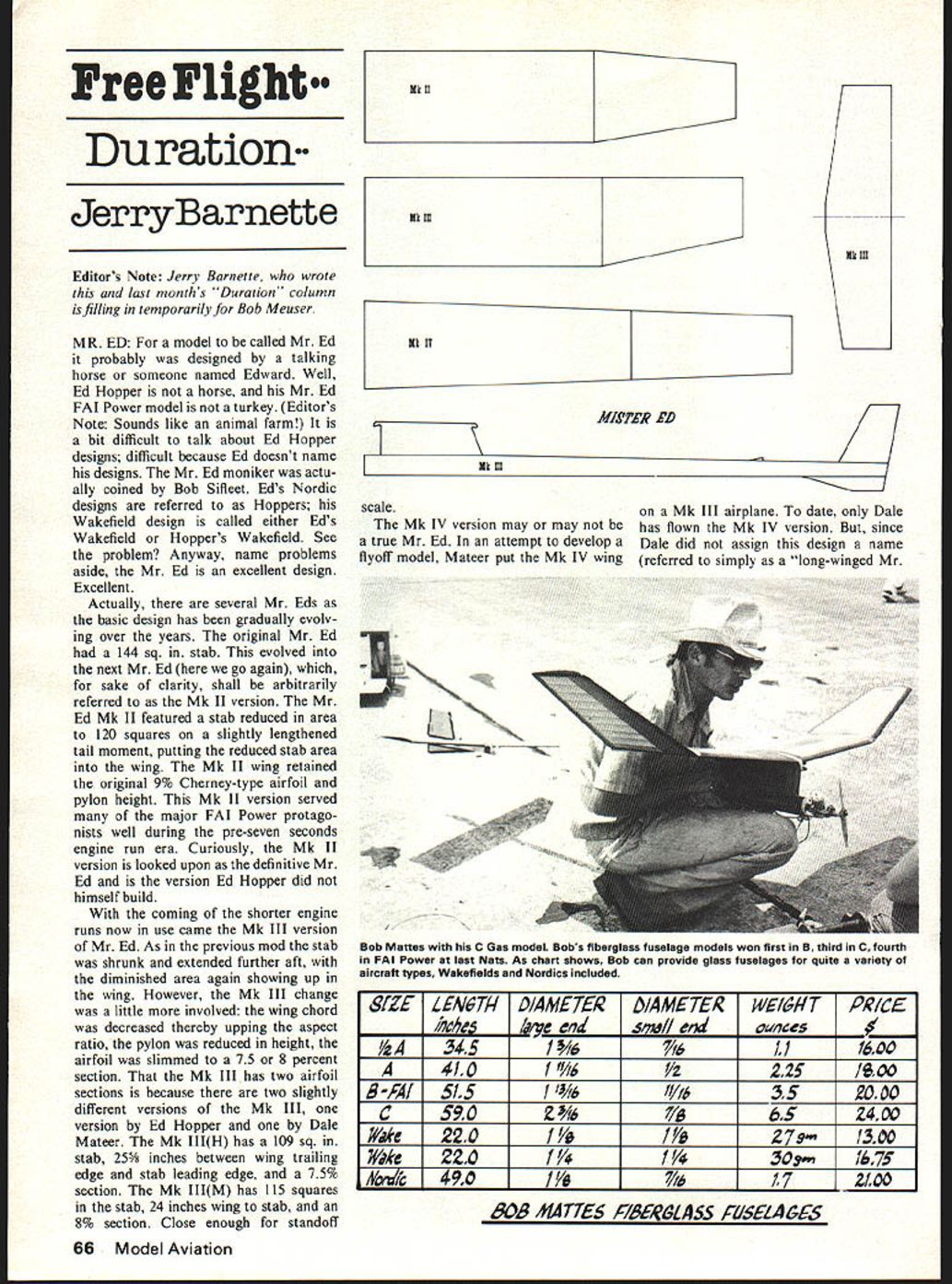
There are several Mr. Eds as the basic design has gradually evolved over the years. The original Mr. Ed had a 144 sq. in. stab. This evolved into the next Mr. Ed (for clarity, arbitrarily referred to here as the Mk II). The Mr. Ed Mk II featured a reduced stab area (about 120 sq. in.) and a slightly lengthened tail moment by moving the reduced stab area aft. The Mk II wing retained the original 9% Cherney-type airfoil and pylon height. The Mk II served many of the major FAI Power protagonists well during the pre-seven-seconds engine-run era. Curiously, the Mk II is often looked upon as the definitive Mr. Ed — and it is the version Ed Hopper did not himself build.
With the advent of shorter engine runs came the Mk III version. As before, the stab was shrunk and extended farther aft, with the diminished area showing up in the wing. The Mk III also reduced wing chord (increasing aspect ratio), lowered the pylon, and slimmed the airfoil to about 7.5–8%. There are two slightly different Mk III versions: one by Ed Hopper and one by Dale Mateer. The Mk III(H) has a 109 sq. in. stab, about 25-5/8 inches between wing trailing edge and stab leading edge, and a 7.5% section. The Mk III(M) has a 115 sq. in. stab, about 24 inches wing-to-stab spacing, and an 8% section.
The Mk IV may or may not be a true Mr. Ed. In an attempt to develop a flyoff model, Mateer put a Mk IV wing on a Mk III airplane; to date only Dale has flown the Mk IV version. Dale did not give this design a separate name (it was referred to simply as a "long-winged Mr.").
So much for the aerodynamic "roots." How do the Mr. Eds perform? Very well. All variants have been very competitive. A common thread among FAI flyers is the design's yeoman performance, well-mannered flying characteristics, and durability. Notably absent from most Mr. Ed discussion are problems, quirks, or shortcomings — because Mr. Ed is remarkably glitch-free. High performance, consistent performance.
Birthday Jig (A personal story)
I came up with this hand-launched-glider (HLG) wing jig the other day. It turns out accurate, identical wings automatically, produces tapered tips, and uses only sandpaper. My son Mike likes HLGs and throws store-bought gliders very well. Mike wanted to fly in the contests we attend, but the Builder of the Model (BOM) rule requires the competitor to have built the model. Mike had not done much building yet, and his seventh birthday was coming up, so I set out to devise something to help him build his own HLGs.
Design requirements for the device:
- Eliminate as much measurement and judgment as possible for the builder.
- Produce accurate, reproducible triangular-airfoiled wings.
- Ensure the finished model complies with the BOM rule.
- Allow a young, inexperienced modeler to use the device with little or no active supervision.
- Be easy to use.
The Birthday Jig meets these objectives and also teaches the need for sanding blocks, proper tools, jigs, and fixtures — valuable lessons, since many kids do not appreciate a sanding block or the time to fabricate jigs.
To construct a Birthday Jig:
- Select an appropriate HLG design, keeping in mind the jig generates triangular airfoil sections. The following assumes a wing layout of constant-chord center panels and tapered tip panels.
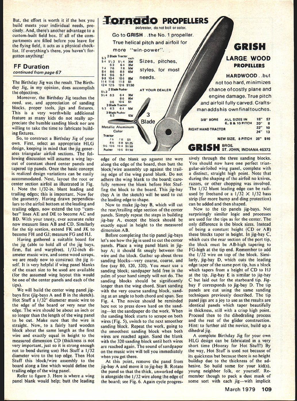
- Layout the root/center-section airfoil (see Fig. 1 in the original sketch). Note the 1/32-in. blunt leading and trailing edges — this is important.
- Geometry: draw perpendiculars to the airfoil bottom at the leading and trailing edges, then extend the top "camber" lines AE and DE to become AC and BD; measure AB and CD. For the tip section, extend FH and JK to become FG and GJ; measure FG and HJ.
Materials: a suitable board (to hold all jig bays; firm, flat, warp-free), 1/32-in. diameter music wire, some wood scraps, and panel blanks sized to the center and tip panels.
Building the center-panel jig bays (A and B):
- Hot Stuff a 1/32-in. diameter music wire to the edge of the board (or very near the edge). The wire should be about an inch longer than the wing panel length and must be straight.
- Make a fairly hard wooden block about the same length as the wire and exactly equal in height to the measured dimension CD. Hot Stuff a 1/32-in. diameter wire to the top edge of this block.
- Hot Stuff this block/wire assembly to the board along the line defining the trailing edge of the wing panel. This is jig-bay A and will be used to cut the leading edge to shape.
For jig-bay B (rear/trailing edge):
- Repeat the steps for jig-bay A, except make the block height equal to the measured dimension AB.
Using the center-panel jig bays:
- Place a wing panel blank in jig-bay A; it should fit snugly between the wire and the block.
- Use three sanding blocks: very coarse (about 80), coarse (about 120), and fine (about 320). You must use sanding blocks; freehand sandpaper will not do. The blocks should be significantly longer than the wing chord.
- Start with the very coarse block, sanding at an angle to both chord and span. Do not press hard — let the sandpaper do the work.
- When the sanding block begins to scrape both wires, switch to the next smoother block. Repeat, progressing to the 320 block until both wires are reached again. The sound of sandpaper on the music wire tells you immediately when you've reached the wire.
- Remove the panel from jig-bay A and move it to jig-bay B. Rotate the panel so the thick, unworked edge is alongside the 1/32-in. wire along the edge of the board.
- Again cycle progressively through the three sanding blocks. You should now have one perfect triangular-airfoiled wing panel with a distinct, straight high point.
- No knives or razors are needed. The 1/32-in. blunt leading edge can be radiused freehand or protected with a 1/32 x 1/32 bass strip that can then be shaped.
Tip-panel jig bays:
- Similar logic applies to the tip panels; the difference is the block sizes taper in height.
- In jig-bay C (which cuts the rear section of the port tip) the block must taper from B-A high at the root to FG high at the tip end; add the 1/32-in. wire on top.
- Jig-bay D (leading-edge taper of the same port tip) has a block tapering from CD to HJ at the tip.
- Jig-bay E corresponds to jig-bay C but for the starboard tip; jig-bay F corresponds to jig-bay D.
- Cut the tip panels with the same progressive sanding technique. The tip-panel jigs produce identical panels that taper beautifully in thickness with a crisp high point.
- Proceed to dihedraling and the rest of the glider construction. Hint: build a dihedral jig to aid the novice.
A complete Birthday Jig for your HLG design can be fabricated quickly (hooray for Hot Stuff!). Hot Stuff is used not for speed but because it produces no height buildup due to adhesive thickness. Remember to pack a dust mask with each jig and include clear instructions/orders to use it when sanding.
More Help for Junior
The Birthday Jig should allow a new Junior (or Senior) to comply with the BOM rule and compete in Open HLG. But if Junior wants to compete in a more involved event, consider the Team Entries rule (Section I, paragraph 9 of the rule book). Bill Hunter and his son Travis used this rule: together they built a 1/2A gas model and flew it as a Team entry in contests (in Open). It's a good way to teach a youngster the ropes. After a contest season as a team, Junior will probably be ready to compete alone in his own age category the following year. Team flying may also improve the adult's skills — the family that flies together...
The UPS Man Cometh
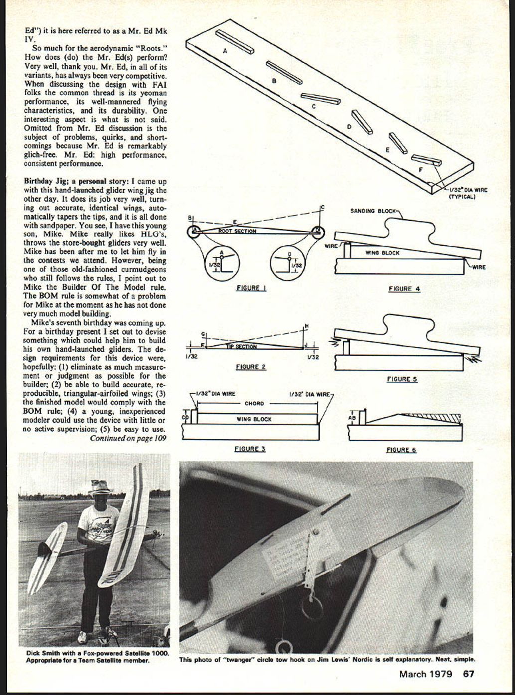
A UPS delivery brought a long, narrow, super-sturdy wooden box containing fiberglass fuselages from Bob Mattes. Bob protects his items extremely well; opening the crate took some toil. The fuselages inspected well — strong, light, excellent workmanship, no excess resin blobs or air bubbles, nicely shaped, straight and true. Bob's instruction sheet (covering firewall, timer, pylon, and stab-platform installations) is clear and helpful.
(Note: Bob makes tapered tubes for power models and also offers constant-diameter tubes for Wakefield and Nordic use.)
Transcribed from original scans by AI. Minor OCR errors may remain.

