
Free Flight: Duration
Bob Meuser
B AND B Special
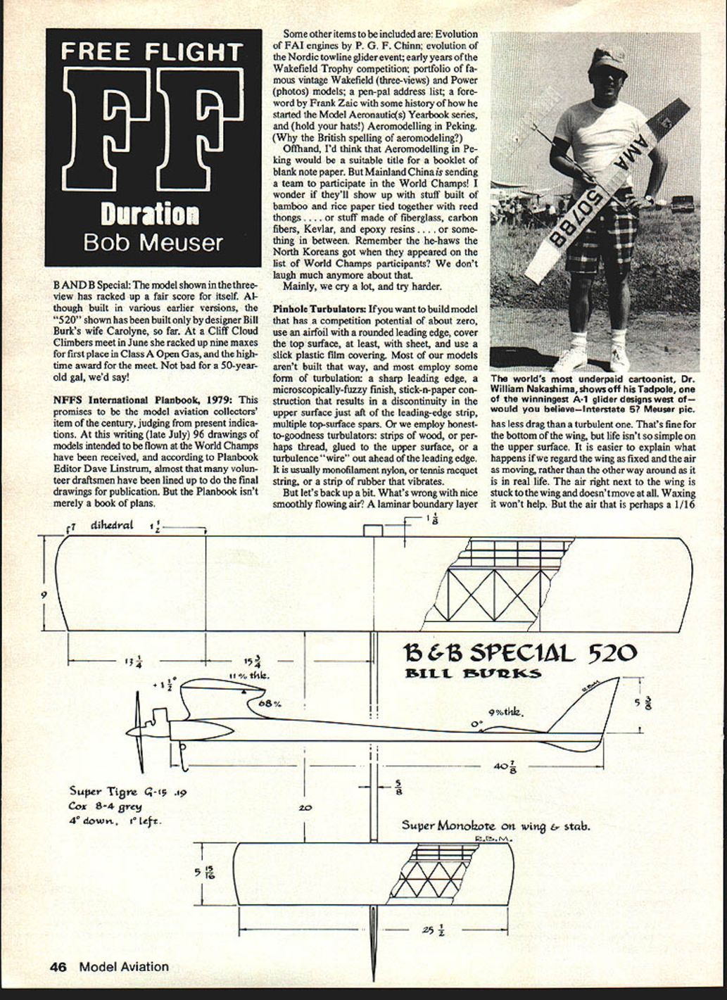
The model shown in the three-view has racked up a fair score for itself. Although built in various earlier versions, the "520" shown has been built only by designer Bill Burks' wife Carolyne so far. At a Cliff Cloud Climbers meet in June she racked up nine maxes for first place in Class A Open Gas, and the high-time award for the meet. Not bad for a 50-year-old gal, we'd say!
NFFS International Planbook, 1979
This promises to be the model aviation collectors' item of the century, judging from present indications. At this writing (late July) 96 drawings of models intended to be flown at the World Champs have been received, and according to Planbook Editor Dave Linstrum, almost that many volunteer draftsmen have been lined up to do the final drawings for publication. But the Planbook isn't merely a book of plans.
Some other items to be included are:
- Evolution of FAI engines by P. G. F. Chinn
- Evolution of the Nordic towline glider event
- Early years of the Wakefield Trophy competition
- Portfolio of famous vintage Wakefield (three-views) and Power (photos) models
- A pen-pal address list
- A foreword by Frank Zaic with some history of how he started the Model Aeronautics Yearbook series
- Aeromodelling in Peking (hold your hats!) — (Why the British spelling of aeromodelling?)
Offhand, I'd think that Aeromodelling in Peking would be a suitable title for a booklet of blank note paper. But Mainland China is sending a team to participate in the World Champs! I wonder if they'll show up with stuff built of bamboo and rice paper tied together with reed thongs ... or stuff made of fiberglass, carbon fibers, Kevlar, and epoxy resins ... or something in between.
Remember the he-haws the North Koreans got when they appeared on the list of World Champs participants? We don't laugh much anymore about that. Mainly, we cry a lot, and try harder.
Other potential Planbook or World Champs topics people will write about (and some probably will) include:
- Thermal-detection devices and techniques
- Team organization and management
- How to cheat without getting caught
- And, oh gosh, you could write a book. And they will.
Pinhole Turbulators
If you want to build models that have a competition potential of about zero, use an airfoil with a rounded leading edge, cover the top surface, at least, with sheet, and use a slick plastic film covering. Most of our models aren't built that way, and most employ some form of turbulation: a sharp leading edge, a microscopically-fuzzy finish, stick-and-paper construction that results in a discontinuity in the upper surface just aft of the leading-edge strip, multiple top-surface spars. Or we employ honest-to-goodness turbulators: strips of wood, or perhaps thread, glued to the upper surface, or a turbulence "wire" out ahead of the leading edge. It is usually monofilament nylon, or tennis racquet string, or a strip of rubber that vibrates.
But let's back up a bit. What's wrong with nice smoothly flowing air? A laminar boundary layer has less drag than a turbulent one. That's fine. Life isn't so simple on the upper surface, and it's easier to explain what happens if we regard the wing as fixed and the air as moving. The air right next to the wing is stuck to the wing and doesn't move at all. The air that is perhaps 1/16" or 1/32" away from the surface is moving full speed. Between the boundary layer and the freestream the speed of the airflow increases from zero to full speed.
On the front part of the wing's upper surface the speed of the air is higher than the local freestream, which creates suction and results in lift. The air must slow down again to rejoin the freestream after it passes the wing. If it slows down in an orderly fashion the air right next to the surface, already going very slowly, and the mainstream slows down some air within the boundary layer brought to a dead standstill; the air closer to the surface moves forward. Such a situation is unstable and doesn't really persist. The flow instead separates from the wing surface leaving a thick separation region where the flow goes its own way. The pressure in the separation region is low and the lift is less than if the flow followed the wing contour.
The solution is to make sure the boundary layer is turbulent. A turbulent boundary layer has the stagnant air next to the surface continuously mixed with fast-moving mainstream air and is less likely to reverse direction.
An effective, easily applied, seldom-seen method of inducing turbulence uses pinhole turbulators — merely holes in the upper (or possibly lower) surface of the wing near the leading edge to form a turbulator. These were tested extensively by the Model Aerodynamics Research Project in England some 25 years ago in a special low-turbulence wind tunnel. Four-inch-chord wings of both built-up and sheet-covered construction were tested with various hole configurations. For the built-up wing, holes of .028-inch diameter were pierced through the paper just aft of the leading-edge strip, and .040-inch diameter holes were drilled through the leading-edge strip. For the sheet-covered wing, .020-inch diameter holes were drilled through the sheet covering just aft of the leading-edge strip.
Here is what they found:
- A span-wise hole spacing of 25% chord — 1-inch spacing for the 4-inch chord — is sufficient to produce the full effect; adding more holes helps very little.
- The greatest effect was achieved on the sheet-covered surface, but merely because it was the worst of the lot to begin with (critical Reynolds number was cut in half).
- The greatest effect is achieved when both top and bottom surfaces are pierced, or when the holes go through the leading-edge strip. Presumably air under pressure enters the bottom and jets out the top holes.
- Some effect is achieved by piercing only the upper surface of either type of wing just behind the leading-edge strip. Apparently the combination of the hole and the volume of air within the wing sets up a resonance which alternately pumps air in and out of the holes (Helmholtz resonator).
- At Reynolds numbers above the critical value (no separation, maximum lift) the drag for the unturbulated section is somewhat less than that for the turbulated section. Lesson: don't use larger turbulators, or a closer hole spacing, than you have to.
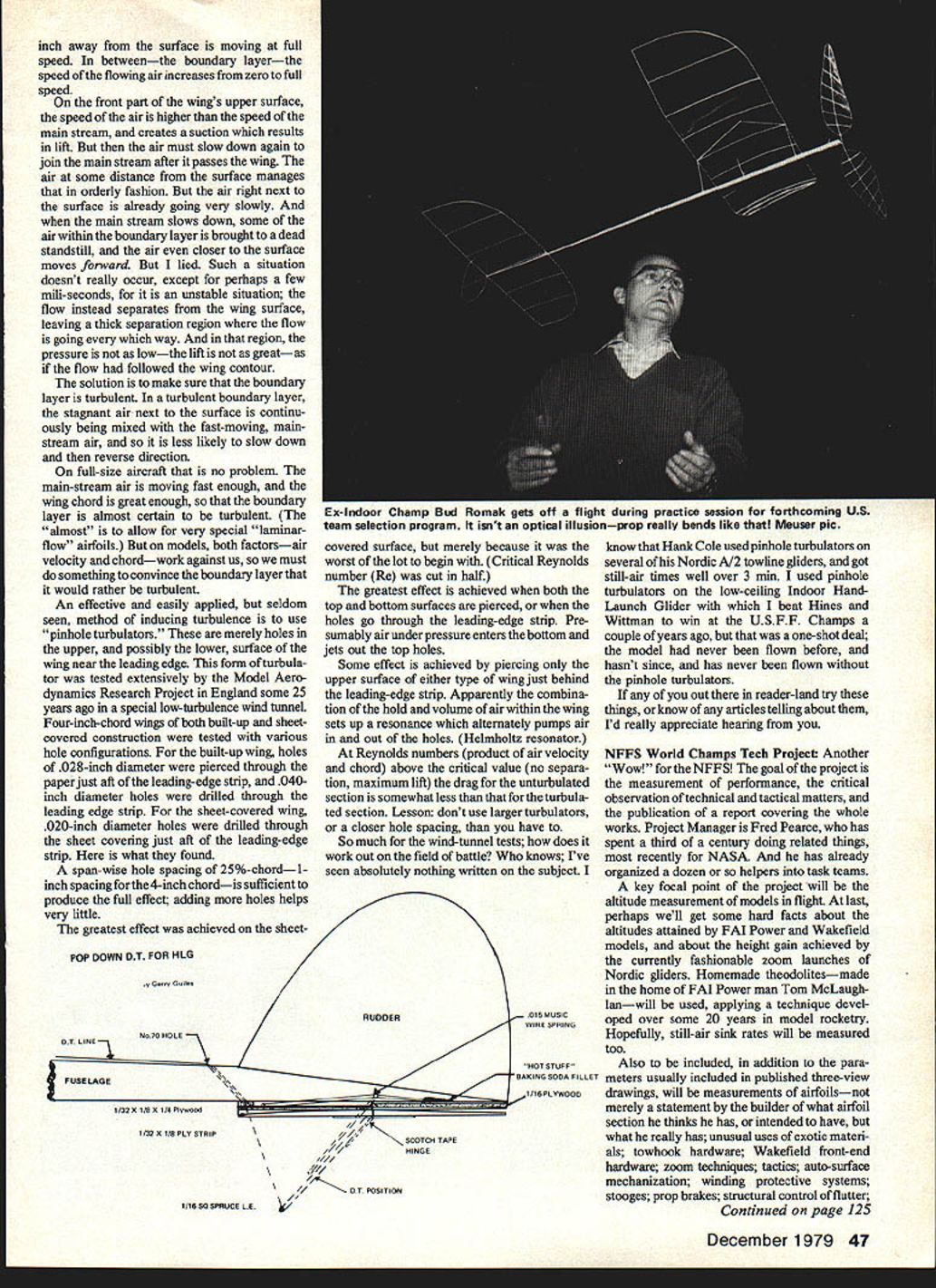
So much for the wind-tunnel tests; how does it work out on the field of battle? Who knows; I've seen absolutely nothing written on the subject. I know that Hank Cole used pinhole turbulators on several of his Nordic A/2 towline gliders, and got still-air times well over 3 minutes. I used pinhole turbulators on the low-ceiling Indoor Hand-Launch Glider with which I beat Hines and Wittman to win at the U.S.F.F. Champs a couple of years ago, but that was a one-shot deal; the model had never been flown before, and hasn't since, and has never been flown without the pinhole turbulators.
If any of you out there in reader-land try these things, or know of any articles telling about them, I'd really appreciate hearing from you.
Model Models?
An article in the May issue of Sport Aviation by Takashi Arita tells how small, simply built, all-balsa gliders can be used to predict the stability characteristics of proposed full-size aircraft. Strangely enough, simple flat wings work as well as more elaborate shapes for many of the tests; the article discusses methods, limitations and interpretation of results, including the effects of scale and Reynolds number on the measured characteristics. High-power flight characteristics can be simulated by a mild chuck.
The article claims that control characteristics can be simulated too, by cutting away the control surface and taping it back in the deflected position. The author cites cases where unusual characteristics, and their cures, were predicted by small chuck-glider tests and later confirmed by expensive wind-tunnel tests and RC model programs.
Of course, the models must be accurately constructed, and attention must be paid to the accuracy of incidence angles and CG positions. And the model must be launched at the proper flight attitude and speed.
I wonder why we don't use this technique as a design aid for free-flight competition and sport models. It has been done, of course, but it isn't done very often. One reason is that we are a bunch of copy cats. Basic area ratios, moment arms, dihedral angles, and CG positions have been pretty well standardized. But before trying something really new—a T-tail, negative dihedral stab, canard, winglets, whatever—wouldn't it pay to spend an hour or two doing a bit of cut-and-try with a chuck glider first? Certainly FF scale modelers should be able to profit by the technique, except perhaps for the few who are blessed with the knack of being able to make any fool thing fly. (Hello there, Bill Warner.)
Of course, the technique shouldn't work—Reynolds Number and all that—but it apparently does. I recently built a model that was absolutely unstable. (Perhaps "bi-stable" would be a more accurate description; it was perfectly stable in either a normal glide or a near-vertical dive!) The model wasn't all that far out, and should have flown well, but didn't. I might have profited from a technique that shouldn't work but does.
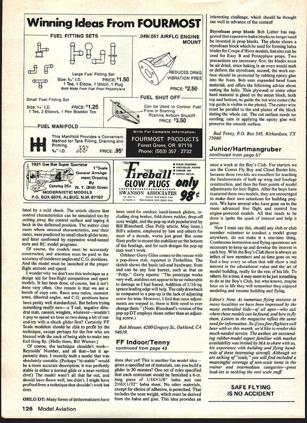
Many forms of dethermalizers have been used for outdoor hand-launch gliders, including drag brakes, fold-down rudder, drop-off nose weight, and the pop-up stab popularized by Bill Blanchard. Bill's scheme, employed by him and others for most of a decade, works just great. But some fliers prefer to mount the stabilizer on the bottom of the fuselage, and for such designs the pop-up stab won't work.
Orbiter Gerry Giles comes to the rescue with a pop-down stab, reported in Torbellino. The sketch shows the basic tail-end hardware; the front end can be any fuse burner, such as that on "Polly." Gerry reports: "The prototype works very well, and does not appear to be as vulnerable to damage as I had feared. Addition of a 1/16-in. spruce leading edge will help. The only drawback as compared to a pop-up is the lack of an adjusting screw for trim. However, I find that once adjustments are warped in, there is little need to ever change them." (Note: Blanchard's version of the pop-up DT employs shims rather than an adjusting screw.)
Bob Meuser 4200 Gregory St. Oakland, CA 94619
Transcribed from original scans by AI. Minor OCR errors may remain.

