
Free Flight: Duration
Bob Meuser
Variable-configuration aircraft (VCA)
This month I'll start off with one of my favorite subjects—variable-configuration aircraft (VCA). I define VCA as any aircraft that changes its shape during flight, particularly as applied to free-flight (FF) model aircraft. That includes wing-swingers, folders, flappers, and models with automatically controlled or programmed control surfaces. For the moment I'll concentrate on folders: models whose wings are folded during part of the flight.
The basic goal of a folder is simple: a low-drag, low-lift configuration for the high-speed powered climb and a large-area, high-lift configuration for the glide. The idea goes back a long way. Mid‑1930s toy gliders used balsa-sheet wings that folded back against the fuselage during a high-speed launch and popped out as speed fell off. A modern counterpart is Johnny Carr's Invader (marketed by CMI Airplane Kits).
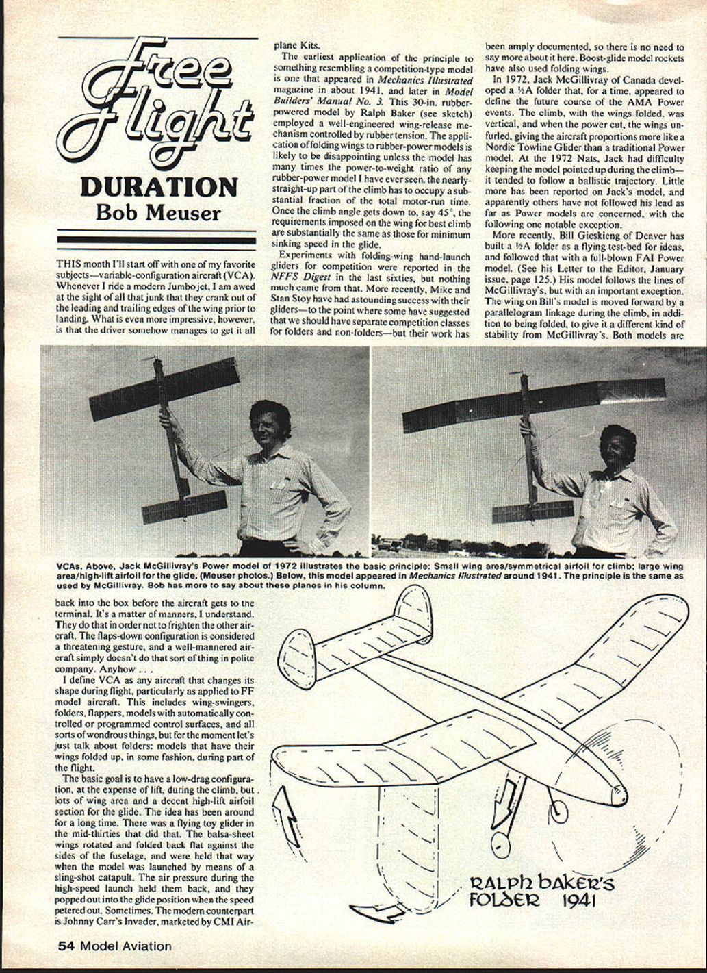
An early application to a competition‑type model appeared in Mechanix Illustrated around 1941 and later in Model Builder's Manual No. 3: a 30‑in. rubber‑powered model by Ralph Baker with a well‑engineered wing‑release mechanism controlled by rubber tension. Note: folding wings on rubber‑powered models usually disappoint unless the model has an extreme power‑to‑weight ratio; a near‑vertical climb must occupy a substantial fraction of the motor run for folders to be worthwhile.
Experiments with folding‑wing hand‑launch gliders were reported in the NFFS Digest in the late 1960s but produced little. More recently Mike and Stan Stoy have had remarkable success with folding gliders—so successful that some suggested separate competition classes for folders—but their work is well documented and needs no repeat here. Boost‑glide model rockets have also used folding wings.
In 1972 Jack McGillivray (Canada) developed a 1/2A folder that for a time seemed to point the way for AMA power events: the climb with wings folded vertically, power cut, then the wings unfurled to a towline‑glider configuration. At the 1972 Nats the model tended to follow a ballistic trajectory and was hard to keep pointed up during climb. Little has been published about McGillivray's model since.
More recently Bill Gieskieng (Denver) built a 1/2A folder as a flying test bed and followed with a full‑blown FAI power model. Bill's design follows McGillivray's general idea but adds a parallelogram linkage that moves the wing forward during climb as well as folding it—this gives a different kind of stability. During initial testing, twin rudders were folded during climb to reduce directional stability; that proved overkill (the tail wagged) and the rudders were later glued solid. Using unequal arm lengths in the parallelogram can change wing incidence as it moves between climb and glide positions, but that adds complexity; incidence change is often better done at the tail where it can be controlled independently.
A warning: VCA design is not for neophytes. Success, if it comes at all, usually requires much experimentation and refinement.
Correction note: In the December 1980 issue we incorrectly attributed the design of Jack McGillivray's Missel Thrush Rubber Scale ship to Bill Noonan. Jack's design is his own; Bill's is a different scale design. Thanks to Terry Jenkins for pointing this out.
SNART and related events
Think SNART: now is the time to start planning for the Sixth NIMAS Annual Record Trials (SNART), which precede the Twenty‑Hour Second World Peanut Gran Prix (TFHSWPGP) sponsored by MIAMA (Miami Indoor Aircraft Model Association). NIMAS stands for National Indoor Model Aircraft Society.
Details:
- SNART includes all Indoor, Indoor Scale, and Peanut Scale events.
- It starts at 9 a.m. on Wednesday, June 24.
- The Peanut Gran Prix runs from 8 p.m. on June 26 to 8 p.m. on June 27 and includes two award banquets.
If you think you might want to enter, write to: Dr. John Martin 3227 Darwin St. Miami, FL 33133
Editor’s note: The 1981 AMA Nationals' indoor events are scheduled at the same West Baden site on June 20–23. See the Competition Newsletter section of the February issue for more details.
Wing construction (duration models)
Many wing construction techniques aim to balance light weight, strength, freedom from warp and twist, and accurate airfoil and incidence distribution. For duration models also add economy—cheapness—and ease of field repair.
One good compromise:
- Sheeted D‑section center for torsional stiffness and leading‑edge protection.
- Built‑up outer panels to save weight and ease repair.
Recommended materials (typical):
- 1/32‑in. sheet for sheeting
- 1/16 x 1/8 cap strips
- 1/32‑in. ribs
- 1/16‑ or 3/32‑in. main spar
Keep glue joints light and fair; sand away excess adhesive.
Covering and finish
Keep coverings and finishes as light as practical:
- Ultralight plastic films or lightweight tissue sealed with thin dope are preferred.
- Heat‑shrink films may be used, but be careful of thermal stresses that can warp the structure.
Trim and flying
- Trim for gentle climbs and long, slow glides.
- Indoor ships: modest climb angles and good low‑speed penetration.
- Outdoor duration ships: trim for expected climb conditions and circle size.
- Small adjustments of incidence, rudder, and tip dihedral usually cure undesirable tendencies.
Balance and strength
- Always statically balance fore and aft and check lateral balance.
- Add only the minimum nose weight needed for stability.
- Reinforce high‑stress areas: wing roots, motor peg or rubber hooks, and landing points—without adding unnecessary weight.
Repair and spares
Design for field repair. Keep a small box of spares:
- Spare ribs and cap strips
- Small sheet of 1/32‑in. balsa
Quick repairs can salvage a flight and avoid major rebuilding.
Rib and trailing‑edge construction
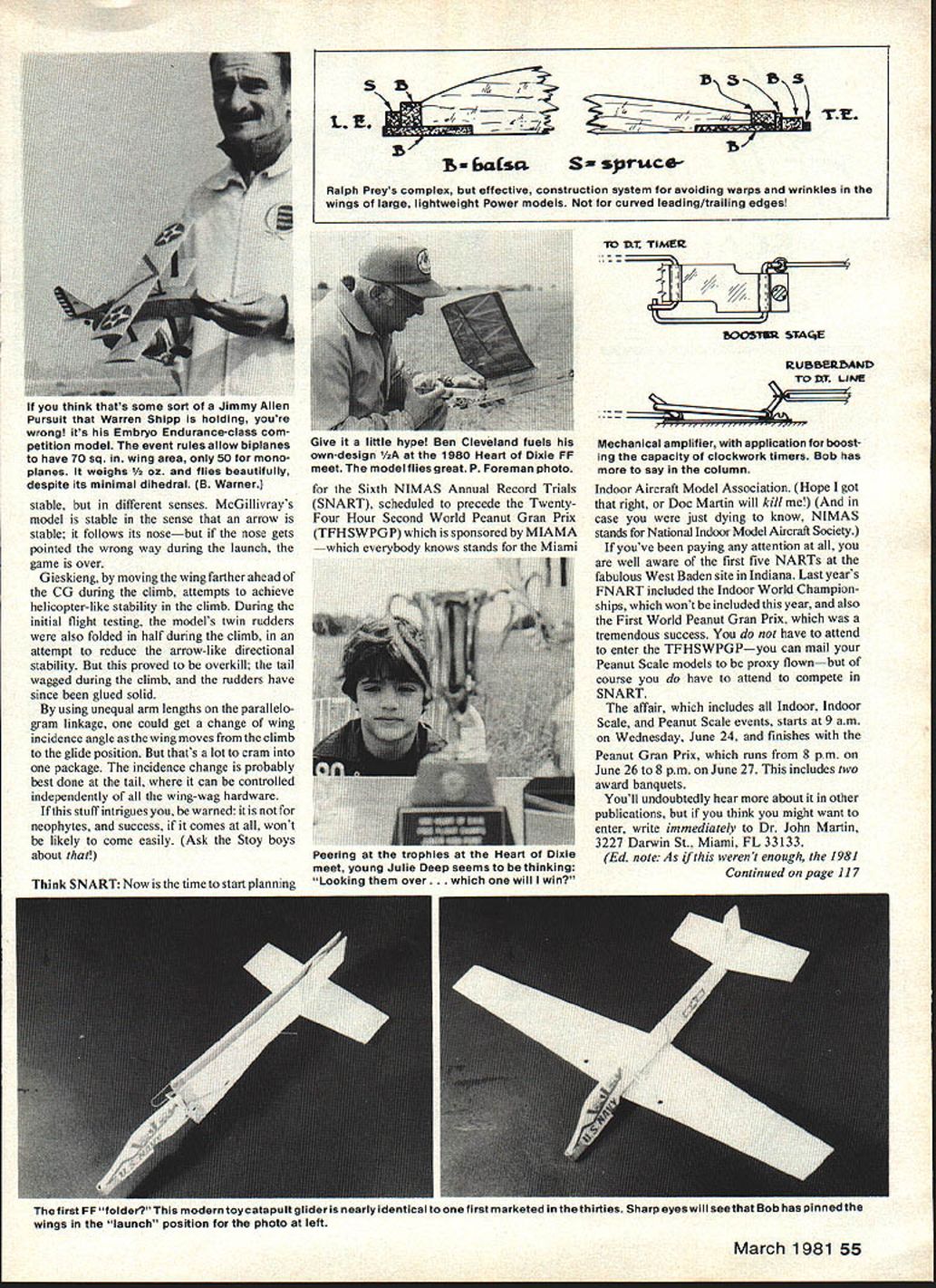
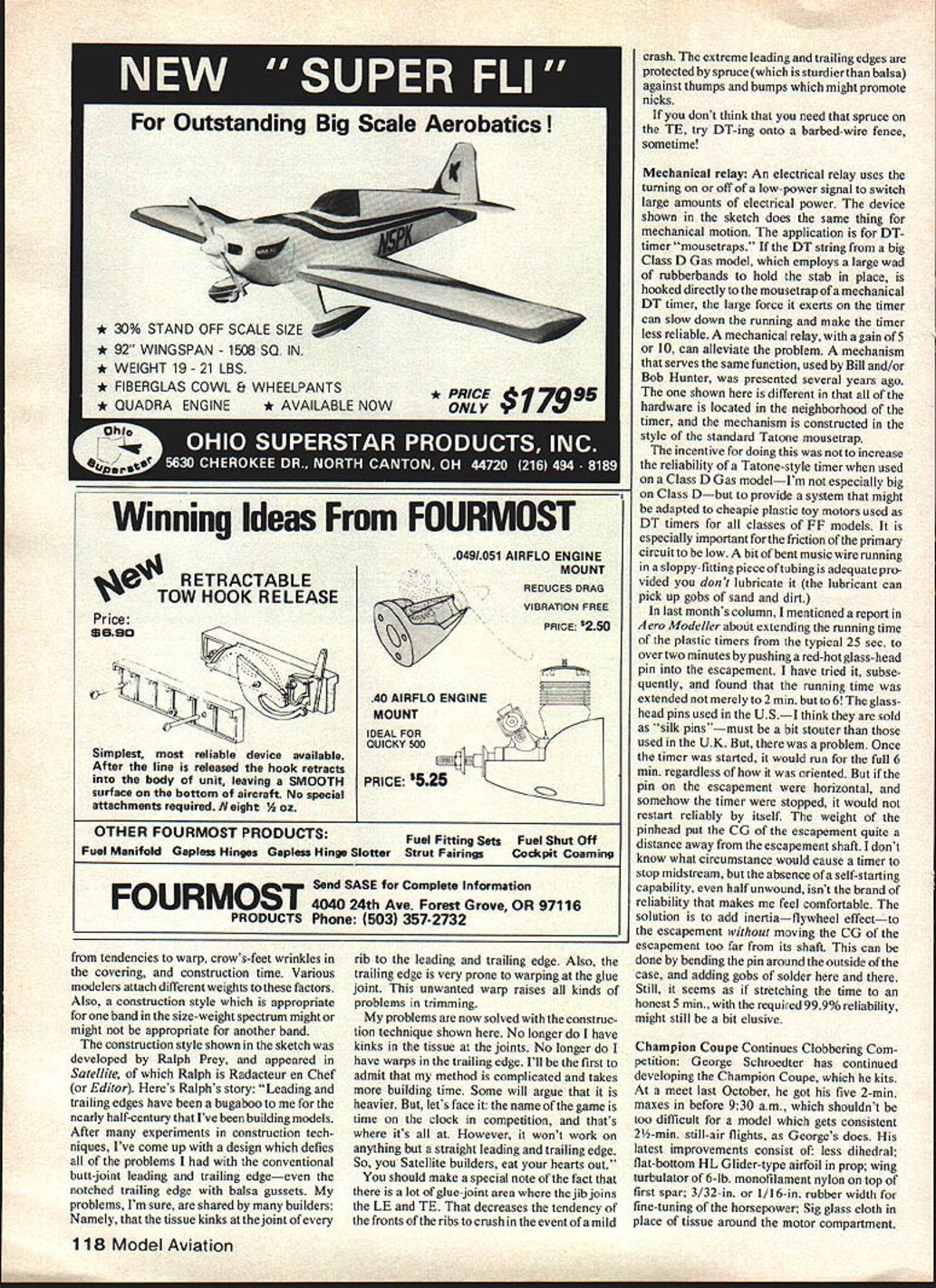
The trailing edge is particularly prone to warping at glue joints, which causes trimming headaches and tissue kinks at joints. My preferred technique (admittedly more time‑consuming) eliminates tissue kinks and trailing‑edge warps by increasing glue‑joint area where ribs join the leading and trailing edges and protecting extreme edges with spruce rather than balsa.
Advantages:
- Larger glue areas reduce rib front crushing in mild crashes.
- Spruce on leading and trailing edges resists dings and nicks.
- The method may add a bit of weight but improves durability and reduces field repair time—important in competition where "time on the clock" is the goal.
If you doubt the need for spruce on the trailing edge, try DT‑ing onto a barbed‑wire fence sometime.
Mechanical relay for DT timers
An electrical relay uses a low‑power signal to switch larger power. A mechanical relay can do the same for motion and is useful on DT‑timer "mousetraps." Problem: a heavy DT string (e.g., Class D Gas with a large rubber‑band wad holding the stab) hooked directly to a mousetrap can slow the timer and reduce reliability. A mechanical relay with a gain of 5–10 alleviates this.
Design notes:
- Put all hardware near the timer, constructed in the style of a standard Tatone mousetrap.
- The system can be adapted to cheap plastic toy motors used as DT timers for many FF classes.
- Keep friction in the primary circuit low. A short length of bent music wire running in a sloppy‑fit tubing works well if you do not lubricate it (lubricant attracts dirt and sand).
Extending plastic timer running time
I referenced an Aero Modeller report that claimed extending plastic timer running time (typically ~25 sec) to over two minutes by pushing a red‑hot glass‑head pin into the escapement. I tried it and extended running time to about six minutes. However, a problem arose: once started the timer would run the full six minutes regardless of orientation, but if the escapement pin were horizontal and the timer were stopped, it might not reliably restart on its own. The added pinhead shifted the escapement CG away from the shaft, reducing self‑starting reliability.
Partial solution:
- Add flywheel inertia to the escapement without shifting its CG too far. Bend the pin around the outside of the case and add small blobs of solder to build inertia.
- Even so, achieving a genuine 5‑minute timing with near‑100% reliability remains challenging.
Champion Coupe developments
George Schroeder continues developing the Champion Coupe (a kit he sells) with outstanding contest performance. At one meet he recorded five 2‑minute maxes before 9:30 a.m., three in the first hour.
Notable features of his latest improvements:
- Less dihedral
- Flat‑bottom, high‑lift glider‑type propeller airfoil
- Wing area ~6.0 sq. in.
- Monofilament nylon on top of the first spar
- 3/32‑in. or 1/16‑in. rubber under the first spar
- 3/32‑in. long keel
- Tissue around the motor compartment
These refinements contribute to consistent start‑air flights around 2½ minutes.
Bob Meuser 4200 Gregory St. Oakland, CA 94619
Transcribed from original scans by AI. Minor OCR errors may remain.

