

Free Flight: Duration
Bob Meuser
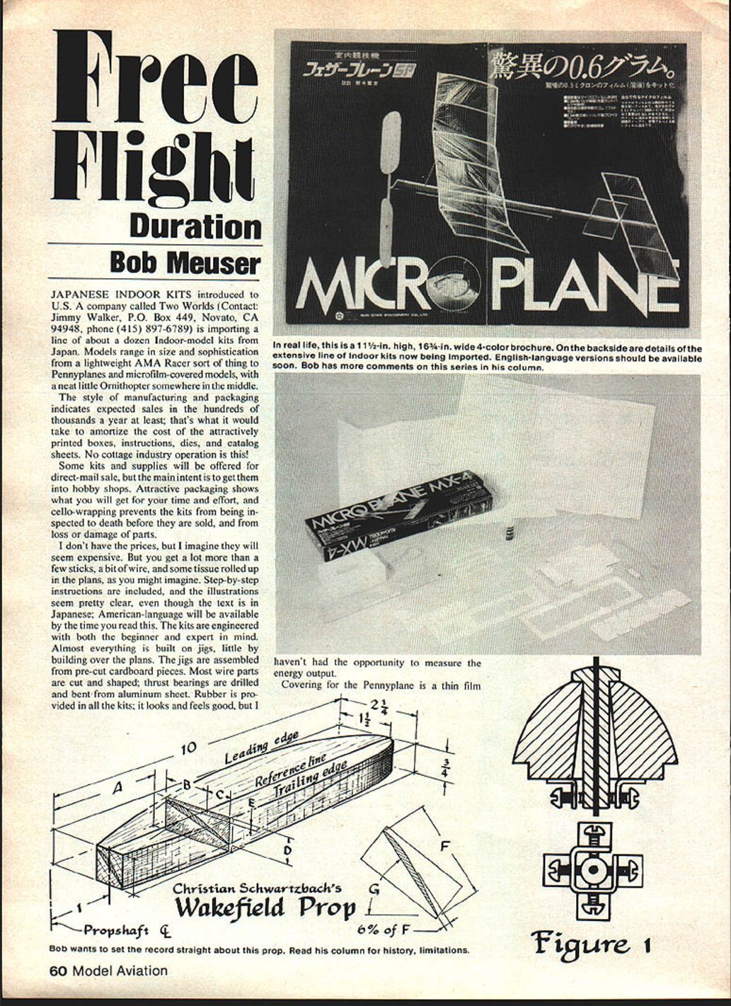
JAPANESE INDOOR KITS introduced to U.S. by a company called Two Worlds (Contact: Jimmy Walker, P.O. Box 449, Novato, CA 94948, phone (415) 897-6789) is importing a line of about a dozen indoor-model kits from Japan. Models range in size and sophistication from a lightweight AMA Racer sort of thing to pennyplanes and microfilm-covered micro models, with a neat little ornithopter somewhere in the middle.
The style of manufacturing and packaging indicates expected sales in the hundreds of thousands a year at least; that's what it would take to amortize the cost of the attractively printed boxes, instructions, dies, and catalog sheets. No cottage-industry operation is this!
Some kits and supplies will be offered for direct-mail sale, but the main intent is to get them into hobby shops. Attractive packaging shows what you will get for your time and effort, and cello-wrapping prevents the kits from being inspected to death before they are sold, and from loss or damage of parts.
I don't have the prices, but I imagine they will seem expensive. You get a lot more than a few sticks, a bit of wire, and some tissue rolled up in the plans, as you might imagine. Step-by-step instructions are included, and the illustrations seem pretty clear, even though the text is in Japanese; English-language instructions will be available by the time you read this. The kits are engineered with both the beginner and expert in mind. Almost everything is built on jigs, little by little building over the plans. The jigs are assembled from pre-cut cardboard pieces. Most wire parts are cut and shaped; some thrust bearings are drilled and bent from aluminum sheet. Rubber is provided in all the kits; it looks and feels good, but I haven't had the opportunity to measure the energy output.
Covering for the pennyplane is a thin film, and its thrust bearings are light injection-molded plastic. Construction should require no more than an hour or two, and from appearances I'd judge the model good enough to rack up half a dozen AMA Junior and Senior records, and possibly a few Open records too!
It is heartening to see good-quality stuff like this on the market. It is good for Free Flight, and it is good for model aviation as a whole. A far cry from some of the kits on the shelves that are virtually unbuildable from the plans and materials supplied (and wouldn't fly anyhow).
Schwartzbach's prop
It has been 13 years since Christian Schwartzbach's Wakefield prop design and design method appeared in the 1968 NFFS Sympo Report. Immediately, the design became popular, and in various modified forms it remains popular. Schwartzbach designed a combination of blade shape and pitch distribution that was supposed to give a blade-loading distribution close to the ideal one. Other combinations, presumably, would have done as well. For example, a helical pitch, and a blade shape designed to match it, might have performed as well, but I have no idea what the blade shape would have had to be; it might be a bit grotesque.
Many designers of outstanding models have used the "Schwartzbach pitch distribution," but their own blade shape. Of course, that blows the whole thing; it's the combination that counts. But if their blade shape isn't too far off Schwartzbach's, they're probably not too bad off. It takes rather gross changes in blade shape to produce mild changes in blade-loading distribution, and such changes in load distribution have a proportionally smaller effect on performance.
Does the fact that these pseudo‑Schwartzbach props drive models that perform exceedingly well prove that they are indeed superior props? Not at all! In competition, it is the whole thing that counts, and the whole is not necessarily equal to the sum of the pieces. A model might perform exceedingly well, not because a certain feature of its design is exceedingly good, but rather despite that feature being less than superior, and because other features are sufficiently superior to compensate.
The Schwartzbach prop worked rather well the way he "loaded" it; it might not do so well at other loadings. That is: an extremely high-power model with correspondingly short motor run might well overload the prop; a long motor run with less pizazz might underload it. Generally speaking, to keep things in line, one should use a scaled-up version for short motor runs, a scaled-down one for "cruisers." And having built one of a particular size, you might find it works better on a fast-climber than on a cruiser. The design can be scaled to suit other classes of models: Coupe d'Hiver, for example. And who will be the first to put a dozen Schwartzbach props on his Peanut Scale Dornier DO‑X?
Occasionally, it pays to go back to original sources. Truth is seldom enhanced through interpretation. (Hmmm! ... I'm beginning to sound like a Fundamentalist!) Anyhow, it seems appropriate at this point in time to publish an original, un‑interpreted Schwartzbach prop design. The design presented here came directly from Schwartzbach and differs slightly from the one presented in the Sympo Report.
Personally, I don't think much of this method for laying out the blank unless one uses blade‑angle templates to fine‑tune the shape; if you simply whittle away "to the lines," it is unlikely that you will get the correct pitch distribution, and it's even a bit unlikely that both blades will be alike, which is perhaps most important. But lots of modelers swear by the method, even without templates; and I know of more than a few who swear at it. Schwartzbach used blade‑angle templates, so I can't knock his application of the method.
As usual, use a long, carbon‑steel knife for carving. A cheap kitchen knife will do, provided it isn't stainless steel. Figure to spend about as much time sharpening the knife as carving; you'll save time in the long run. Use coarse sandpaper, 100 grit, wiped across or diagonal to the grain, not with the grain, until you are within a gnat's eye of the final dimensions. Then use finer grits, ending up with 600 wiped along the grain. And use sharp, unworn, high‑quality paper at all times. (Carving props is good for the spleen.)
Compound angles
When tuning a new model, it is best to start out with the down‑thrust angles specified by the designer. For rubber‑power models, most modelers prefer to keep the shoulder on the noseblock square with the propshaft, and to build the thrustline angles into the front of the fuselage. With a round fuselage, sanding off the side to get both angles correct can be a chore.
You might find it easier to use one of the following methods. Sand off the end of the tube to a certain true angle (which we'll tell you how to determine later), to give pure side‑thrust (no downthrust), then rotate the tube to get the correct downthrust before gluing on the platform. Or, if the wing platform is already in place, set your angle gauge to the true thrustline angle, then rotate the gauge down from the horizontal, and sand the fuselage to fit the gauge. For gas models having an engine mount screwed to the firewall, make a shim tapered to the thrustline angle, then rotate the shim when installing it between the engine mount and the firewall. It is really a lot simpler than I seem to be making it sound.
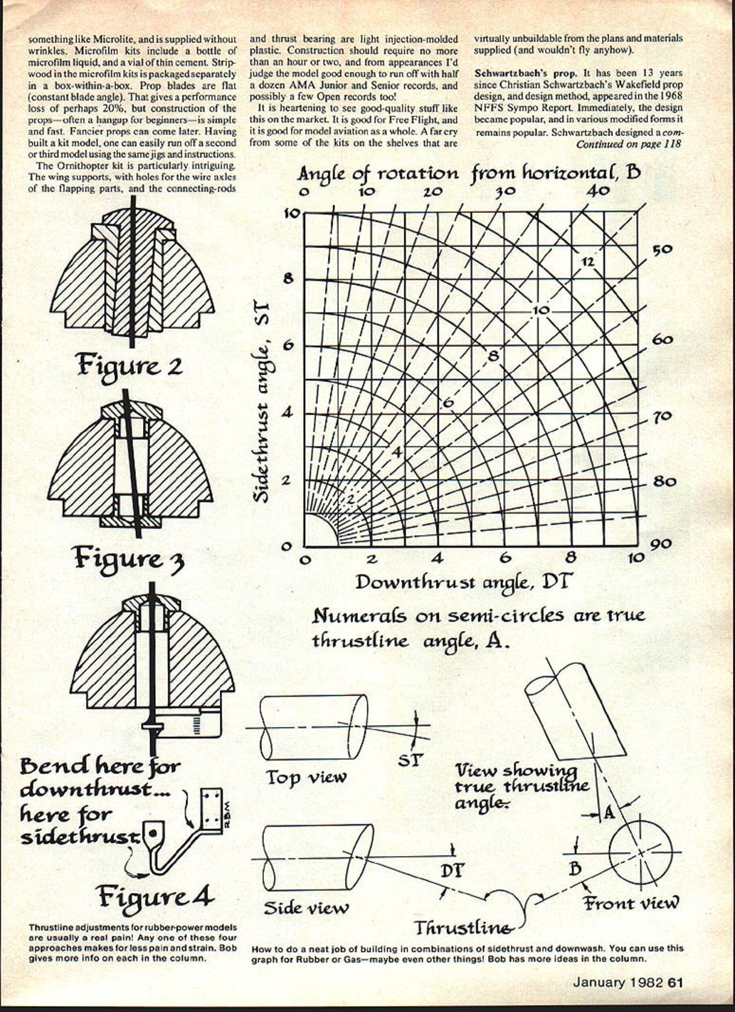
We present two methods for figuring the proper angles: the first, for those who are big on trig and who want split‑hair precision; the second, a more goal‑oriented, graphical approach. For starters, refer to the sketch. The mathematics goes as follows:
ST = side‑thrust angle DT = down‑thrust angle A = true thrustline angle B = angle of rotation, viewed from front
Perform the following calculations: A = √(ST^2 + DT^2) B = cos^-1(ST / A), or B = sin^-1(DT / A)
The graph works like this: Say you want 4° of downthrust and 7° of sidethrust. Go up the line from the 4 on the lower edge of the graph, and to the right from the 7 on the left edge. The lines cross just above the semi‑circle for a true thrustline angle of 8°. They also cross very near to the radial dashed line labeled 30, which is the angle of rotation downward from the horizontal. If you're never going to use angles greater than 5°, you can change the labels on the DT, ST, and A curves from 0, 2, 4, . . . to 0, 1, 2, 3, 4, 5.
Thanks to Bob Lieber for putting me onto this business with a few scribbled lines. And then I had to go and beat the poor thing half to death!
Thrustline adjusters
Typically, thrustline angle adjustments for rubber‑power models are made by putting balsa shims between the noseblock and the fuselage. There is little wrong with that if it is done neatly, although it might not be quite the right thing to do on a Scale model. A decade ago, when I was writing for American Aircraft Modeler, I presented a neat screw‑adjusted scheme used by Don Tryon on his Coupe d'Hiver (Figure 1). A shouldered tube, serving as a journal bearing for the propshaft, was free to rotate in all directions in a plate at the front of the noseblock. At the rear of the noseblock the tube's direction was fixed by four adjusting screws, two horizontal, two vertical. The advantage of such a scheme is that you can return to a previous setting if you don't like the new one, with the mere tweak of a screwdriver, provided you have kept notes on your adjustments.
Perhaps there are alternatives. It always pays to keep looking for alternatives. But, enough for heady philosophy!
A real snazzy way for adjusting the thrustline is to provide two concentric shouldered sleeves (Figure 2). The inner one, which acts as a bearing for the propshaft, rotates in the outer one; the outer one rotates in the noseblock. The holes in each are reamed slightly cockeyed. Rotate one, you change the downthrust angle; the other gives sidethrust angle. A machinist's dream. (Unfortunately, we aren't all machinists.)
There is a variation on that theme, however, that is quite simple. It is based on my astute observation—apparently nobody else has noticed—that a noseblock has both a front side and a backwards side. A thrust button is forced in each side (Figure 3), each having an off-center hole. If it is rigged right, rotating one button changes the downthrust, rotating the other changes the sidethrust. The thrust buttons could be simply the old‑time, dime‑kit wooden ones, plugged and re-drilled, or the more modern nylon ones, such as Peck's.
Or how about a bit of aluminum‑smithing to provide a trick gizmo at the backwards side (Figure 4)? Bend the vertical part and you change the sidethrust angle; bend the horizontal part and you change the downthrust angle. Not as handy or reproducible as Tryon's screw adjustments perhaps. (But I'll bet you could figure out a way to cobble up a spruce-wood wedge, with little marks and numbers on it, to serve as a gauge for judging where you have been and where you have gone.)
Oh well. Just thoughts.
NIMAS and INAV
Inasmuch as Bud Tenny's column on indoor modeling appears less frequently than this one, and Bud can't spend every column pitching for NIMAS, I wonder if all those who might be interested know that the National Indoor Model Airplane Society (NIMAS) actually exists? Membership costs $4.50 a year, and that includes a subscription to Indoor News and Views (INAV). As Bud says, "The intent is to publish 12 issues per year, and do the best we can." If you are interested, send your check to NIMAS, Box 545, Richardson, TX 75080.
Sympo '82 — Call for papers
The National Free Flight Society is soliciting papers for the 1982 NFFS Symposium to be held at the 1982 Nats. Papers will be published in the 1982 Symposium volume whether or not the author is able to present his paper personally at the Nats. Papers should cover some aspect of the science or art of Free Flight models, including:
- technical studies
- design and engineering as applied to models
- history or unusual model aircraft developments
- historical items
Both Indoor and Outdoor Free Flight modeling developments are to be included. Please send proposed papers to Jim Bennett, 324 Helfenstein Ave., St. Louis, MO 63119.
Send the title of the proposed paper together with an abstract of 200 words or more, or a complete paper if it is available. Abstracts should be submitted as soon as possible, the desired deadline being within a month after publication of this notice. The editor, this year, would like to have a complete list of the material to be published by December 31, 1981.
NFFS 1979 World Champs Report
This unique report is totally unlike any other publication ever produced, and it seems quite likely that nothing like it will be produced again. However, judging from sales of the publication, apparently not many Free Flighters are aware of its availability. The report, edited by Fred Pearce, was originally going to be primarily a summary of the altitude measurements and data gathered by Fred's Technical Task Force, but it has expanded to become a lot more.
Fred presents the results of the technically difficult job of measuring the altitude gained by Wakefield rubber-powered and FAI power models during the climb, and the altitude gained by towline gliders as a result of zoom launching, along with a description of the methods used to obtain the measurements. Contest Director Bill Hartill describes how his end of the show was organized and operated. Bob Hatschek describes some of the problems associated with checking approximately 500 models during a 10-hour period in the face of the inevitable enforcement of Murphy's Law. New Zealand's Paul Lagan, fourth place in Wakefield, presents a delightful account of his experience before and during the competition, together with observations on the technical and tactical aspects of the meet. Deborah Renos tells about the team from the People's Republic of China, including the team selection process, technical aspects of the models and materials used, the personalities and lifestyles of the modelers, and the team members' observations of our lifestyles. Fred Pearce presents results of tests on some of the most recent kinds of rubber, especially those kinds used by World Champs teams, and including the home-brew rubber used by the Chinese.
Reports by a multitude of authors, edited by Dennis Mihora (Nordic) and Chris Matsuno (Wakefield), include observations of the teams and individuals in action, technical aspects of the models and equipment, interviews with competitors, and a host of other subjects. The FAI Power competition is covered round-by-round in an account by Fred Pearce, analysis of climb patterns by Andrew Bauer, and observations by Ralph Prey (a greatly expanded version of his story which appeared in Free Flight).
There are also dozens of photographs and around 30 drawings of the top models, including some of their features.
You can order the report from NFFS Publications, 4858 Moorpark Ave., San Jose, CA 95129. Pricing and postage:
- Price: $7.50 for NFFS members and non-residents of the U.S.; $8.50 for others.
- Handling and postage: $2 for any number of copies sent anywhere in the world (4th class).
- Airmail in the Americas: $3 per copy.
- Airmail to Europe: $4 per copy.
- Far East and Pacific by air: $5 per copy.
Bob Meuser, 4200 Gregory St., Oakland, CA 94619.
FF Indoor / Tenny
Continued from page 62
A drastic thing is the reduced rubber weight. Erv feels that even if the current model size is not reduced, the motor weight should be reduced. He arrived at that conclusion after several years of test-flying models with half-length motors. Such testing has two major advantages: the models can be flown on full torque—fully wound—without climbing to the top of a hangar, and without staying up over half an hour. Thus, both models and time are saved by short-motor tests.
In addition, Erv forecasts that the slightly smaller wing and (probably) much shorter motor stick will fit in a box which can be carried into the cabins of airliners during trips to contests. The model should be much stronger, with about a 5¼‑in. wing chord. Even with the smaller wing chord and span, the wing loading should be about the same due to the lighter motor (about 0.7 grams lighter).
It has been said that this rule places a higher premium on having really good rubber, and this is true. In the long run we must admit that the only winners are those with both good luck and good rubber!
In retrospect, we must remember that the original reason for the change to 65 cm models (first try), and then one gram 65 cm models, was to reduce the flight times so that organizers of World Championships would not have to furnish both staff and site for the relatively long time required to fly off a high-entry World Championship. Neither approach has worked, so the missing ingredient may well be to limit the amount of rubber. One thing for sure—we would have to learn a few things about handling rubber when it is wound to higher relative torque levels, and perhaps we will need to learn more about picking certain kinds of rubber.
One other aspect of the Santa Ana Stick has not been mentioned: the model fits the existing rule, and in fact the smaller, stronger model might be exactly what is needed on cool, turbulent days and in low ceilings. With that in mind, we can assume that anyone who built one to the rules change wouldn't really be building an "orphan" model; it could still be quite useful!
Follow-up. In a couple of past issues, I discussed various field gadgets and methods of winding. I also requested that indoor cabin fliers tell us of their pet methods for safely winding their special beasts. The series of pictures with this column show the most elaborate scheme we've seen, but it really works well in spite of the apparent complexity. The photos show the fixture used by Ron Ganser at the 1981 West Baden Indoor Nats and at the NIMAS SNART event; I believe Ron said it was designed by someone else, and I forgot.
Transcribed from original scans by AI. Minor OCR errors may remain.

