
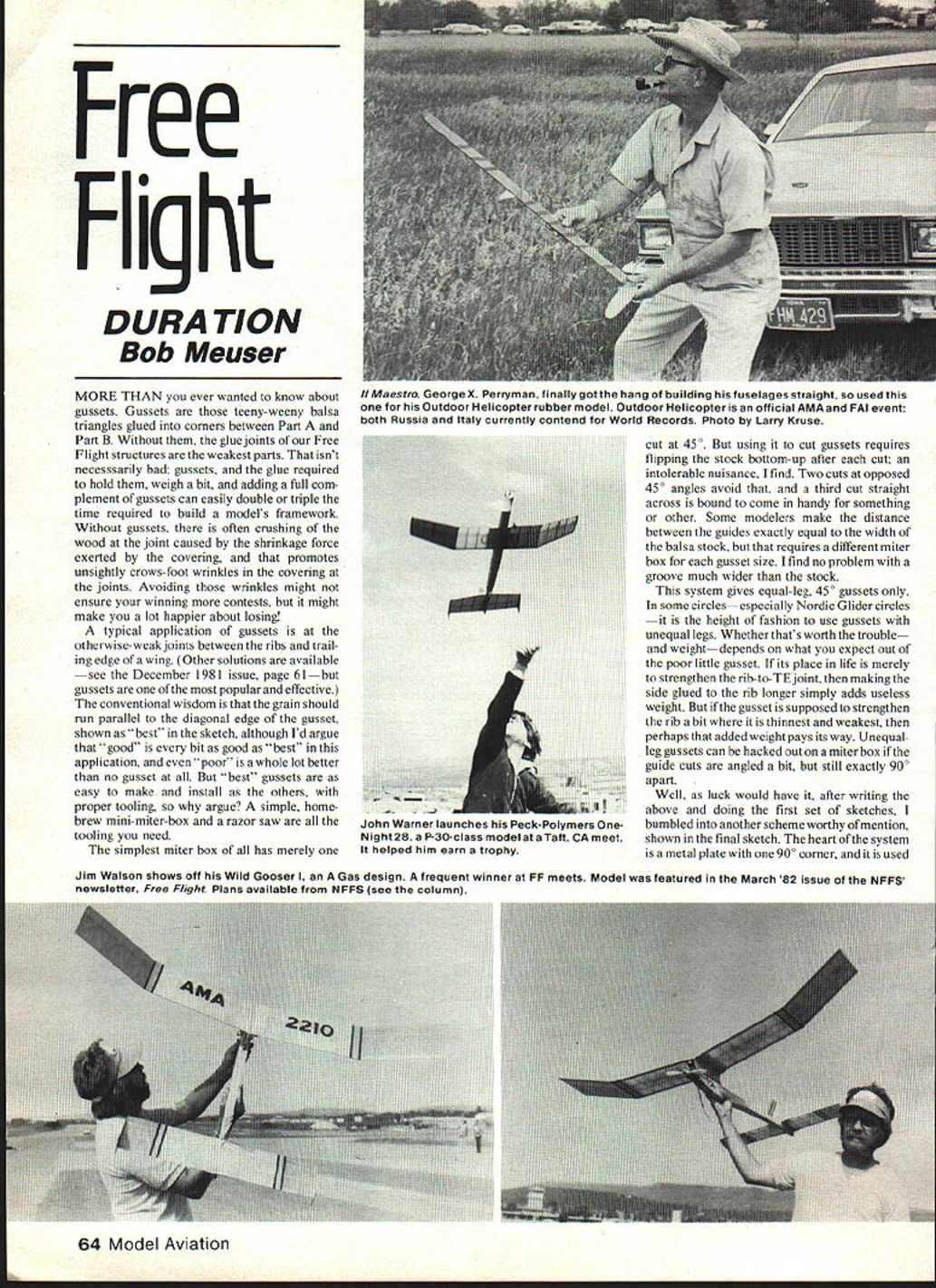
Free Flight: Duration
Bob Meuser
Ah, gussets
More than you ever wanted to know about gussets. Gussets are those teeny-weeny balsa triangles glued into corners between Part A and Part B. Without them, the glue joints of our Free Flight structures are the weakest parts. That isn't necessarily bad: gussets, and the glue required to hold them, weigh a bit, and adding a full complement of gussets can easily double or triple the time required to build a model's framework. Without gussets, there is often crushing of the wood at the joint caused by the shrinkage force exerted by the covering, and that promotes unsightly crow's-foot wrinkles in the covering at the joints. Avoiding those wrinkles might not ensure your winning more contests, but it might make you a lot happier about losing!
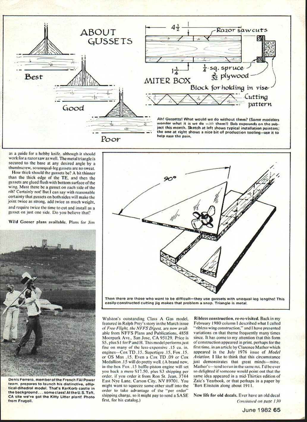
A typical application of gussets is at the otherwise-weak joints between the ribs and the trailing edge (TE) of a wing. (Other solutions are available—see the December 1981 issue, page 61—but gussets are one of the most popular and effective.) Conventional wisdom is that the grain should run parallel to the diagonal edge of the gusset (shown as "best" in the sketch). I'd argue that "good" is every bit as good as "best" in this application, and even "poor" is a whole lot better than no gusset at all. But "best" gussets are as easy to make and install as the others with proper tooling, so why argue?
A simple, home-brew mini-miter box and a razor saw are all the tooling you need. Notes on the miter box approach:
- The simplest miter box has one 45° guide, but that requires flipping the stock bottom-up after each cut.
- Two opposed 45° guides avoid flipping; a third straight-across guide is handy.
- Some builders make the guide spacing equal to the stock width (requiring a different box for each size). I prefer a groove much wider than the stock so one box handles multiple sizes.
- This system yields equal-leg, 45° gussets easily.
Unequal-leg gussets are fashionable in some circles (Nordic Glider builders). Whether they're worth the extra trouble and weight depends on the gusset's intended job. If it's merely to strengthen the rib-to-TE joint, a longer side glued to the rib just adds useless weight. But if the gusset must strengthen a thin, weak rib section, the added material may be justified. Unequal-leg gussets can be made in a miter box by angling the guide cuts while keeping them 90° apart.
Another handy scheme is a metal plate with a 90° corner used as a guide for a hobby knife (it should work with a razor saw as well). The metal triangle is secured to the base at any desired angle by a thumbscrew, so unequal-leg gussets are no sweat.
How thick should gussets be? A bit thinner than the thick edge of the TE, so the gussets glue flush with the bottom surface of the wing. Must there be a gusset on each side of a rib? Certainly not. Gussets on both sides will make the joint roughly twice as strong, add roughly twice as much weight, and require roughly twice the time to cut and install as a single-side gusset. Decide what trade-offs you prefer.
Plans note: Wild Gooser plans (Jim Walston's Class A Gas model) are available from NFFS Plans and Publications, 4858 Moorpark Ave., San Jose, CA 95129. Price $5, plus $1 P&H. This model performs well on many .15 cu. in. engines (Cox TD .15, Supertigre .15, Fox .15, OS Max .15). Even a Cox TD .09 or Cox Medallion .15 will do. (A new, in-the-box Fox .15 baffle-piston engine may be available from Ron St. Jean—write for catalog.)
Ribless construction, re-re-visited
Back in my February 1980 column I described what I called "ribless wing construction," and I've presented variations on that theme many times since. It has come to my attention that this form of construction appeared in print perhaps for the first time in an article by Clarence Mather in the July 1976 issue of Model Aviation. I like to think this demonstrates that great minds—mine and Mather's—tend to run in the same rut. I'd be ever so delighted if someone could point out an earlier appearance (Zaic's Yearbook, mid‑Thirties, or a 1911 paper by "Bert Einstein"?).
New life for old decals
If you have an old decal that tends to fall apart or fuel-attack, brush on a coat of clear urethane varnish over the decal first. This holds the decal together and fuel-proofs it.
Simple rubber-powered timer (conversion and construction)
A practical, low-cost timer can be made using a 1/4-A control-line leadout eyelet mounted in a 3/32‑in. hole. The following is a concise assembly and usage method:
Assembly steps:
- Cement the flange of the eyelet to a plywood disc using a high-viscosity cyanoacrylate or five-minute epoxy.
- Cut a straight pin to project about 1/32 in. over the edge of the disc in a radial orientation and cement it to the disc flange. This acts as the DT (dethermalizer) release pin.
- Clean and roughen the winding shaft with sandpaper or a needle file.
- Slip the disc assembly onto the shaft with a 0.005–0.010 in. shim (single-edge razor blade works) between the flange and the top of the timer. Cement the eyelet to the shaft, taking care not to let cement run into the bearing.
- Push the original plastic winding knob down the shaft until it bottoms on the end of the eyelet. Cut off the protruding shaft and file flush with the top of the knob. Remove the shim.
Operation:
- The timer is powered by a rubberband (the spring is removed). Use a 1/4‑in. loop of .030–.050 indoor rubber hooked over the projecting straight pin and stretched to about twice its normal length.
- The free end of the rubberband is attached to the DT string.
- Wind the rubber around the shaft by twisting the winding knob and letting the rubber climb the shaft. Time is determined by number of turns and rubber characteristics.
- The disc increases torque near the end of the run so the last half-turn provides a cleaner release from the pin.
Notes on durability and handling:
- A prototype has run over 100 cycles at room temperature with no apparent wear or timing change.
- Timers are sensitive to dust and dirt—avoid lubricants and seal them well. If mounted in a pocket in the airplane, seal the interior to keep balsa dust out of the gears.
- Scotch Magic Tape can cover the outside face, but cut a piece of typing paper to fit over the part covering the shaft ends so tape goo won't get into the bearings.
- Vacuum-formed cups are being made for mounting the timers.
Mounting examples:
- Photos show the timer mounted in the nose of Mike Stoy's Wasp (MA plan No. 343).
- Don Lindley prefers mounting the timer in the wing, using the finger-rest fairing for depth (as in his Max Flyer).
This gadget is a developmental prototype—not a finished product—but it's a useful starting point and we hope others will improve on the mechanics and techniques.
Ron throws in the sponge!
In April 1979 I wrote about Ron St. Jean's virtually all-foam construction method. Since then he's advertised under the name Structureless Foam Composites. Ron's technique offers a viable alternative to traditional stick-and-tissue construction and his models have withstood competition flying. Response to his NFFS Digest ad was disappointing; he asked that the ad be killed. Ron later published a full-length article in Model Aviation (April 1982, p. 50). If you don't have access to back issues and want a copy of Ron's article, send a SASE to me. For more information from Ron, write (enclose SASE) to: Ron St. Jean, 3744 East Nye Lane, Carson City, NV 89701.
A sub‑Nats at West Baden
A reminder: a three-day, all-events indoor contest will take place at West Baden, IN on June 14–16. This immediately precedes the traditional NIMAS Records Trials and the Indoor Peanut Scale Grand Prix. Events include all standard AMA-rule-book events plus others (Formula Manhattan, Bostonian, Peanut Scale racing, etc.). This amounts to about two solid weeks of indoor and indoor-scale activities.
The flamingo profile, revisited
The name "flamingo airfoil" must have been coined by someone—no flamingo (or any other creature) ever had such an airfoil. Some literature sketches show an indentation in the lower surface just behind the leading edge (LE) for hawks and eagles—long-dead ones perhaps, but not live birds. A leading-edge flap, as used by Les DeWitt's Iconoclast Wakefield, might work similarly to the Seredinsky foil.
Bill Bogart points out that the Seredinsky "Flamingo Airfoil," discussed in the December 1981 issue, appeared in model aviation literature as early as 1953 (Model Airplane News, October 1953, p. 17). Herman Andresen experimented with Seredinsky-type foils in the 1960s. One application was a Nordic glider with a 10-ft span and aspect ratio 30, aimed at a safe 3 minutes in still air; it fell a second or two short and was abandoned. He also used such foils on a series of low-ceiling indoor hand-launch gliders; the final one had a 28‑in span, 100 sq. in. wing area, and weighed 1/2 oz—achieving respectable times in a gym.
Bob Norton (Bakersfield, CA) found early references in Aero Modeller: Kekkonen's Patti A‑1 Glider (Jan 1965) and J. M. Berthe's Super‑Flamingo A‑2 Glider (Feb 1969), among others.
Bob Meuser 4200 Gregory St., Oakland, CA 94619
Transcribed from original scans by AI. Minor OCR errors may remain.

