
Free Flight: DURATION
Bob Meuser
The Montreal stop
It's funny — you can go 10 years without anyone mentioning a particular subject, then get three letters in the same mail asking about it. Such has been the case with the Montreal stop.
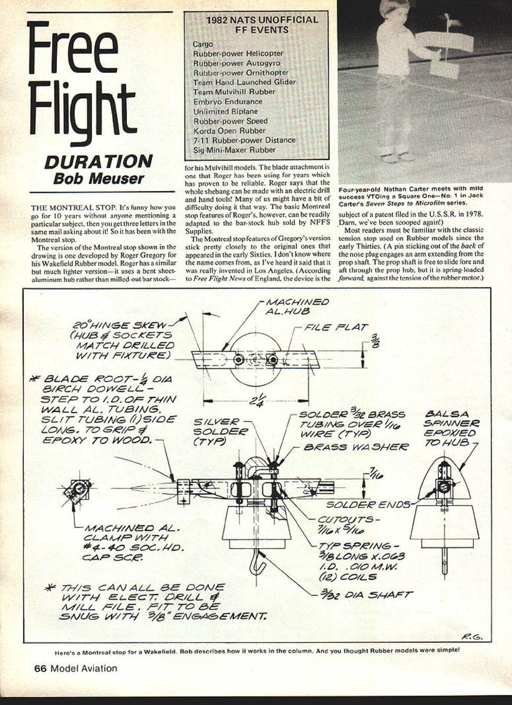
The version shown in the drawing was developed by Roger Gregory for Wakefield rubber models. Roger also uses a similar, much lighter version that employs a bent sheet‑aluminum hub rather than milled bar stock for his Mulvihill models. The blade attachment is one Roger has used for years and has proven reliable. Roger says the whole assembly can be made with an electric drill and hand tools, though many of us might find it a bit fiddly. The basic Montreal‑stop features, however, can be adapted readily to the bar‑stock hub sold by NFFS Supplies.
Gregory's design adheres closely to the original Montreal stops that appeared in the early 1960s. I don't know where the name comes from — I've heard it said that it was really invented in Los Angeles. According to Free Flight News (England), a similar device was the subject of a patent filed in the U.S.S.R. in 1978.
Most readers will be familiar with the classic tension stop used on rubber models since the early 1930s: a pin protrudes from the back of the nose plug and engages an arm extending from the prop hub. The prop shaft is free to slide fore and aft through the hub but is spring‑loaded forward against the rubber motor's tension.
The Montreal stop differs in two important ways:
- It locks the prop shaft based on the torque of the rubber motor rather than its linear tension.
- Once the prop has stopped, it stays stopped (unlike many tension‑stop designs).
Another feature of true Montreal‑stop devices is a locking pin that prevents the prop from rotating after the motor is wound until the flier chooses to launch.
Operating sequence
- Wind the motor.
- The stop pin (right side in Roger's drawing) is pulled out by the force at the end of the L‑shaped part of the prop shaft. Motor torque, combined with friction, holds the pin out.
- When motor torque slacks off to a predetermined level, the spring pushes the pin back in and the prop shaft becomes locked (the prop stops).
- The locking pin (left side in Roger's drawing) is pushed into a hole in the nose block after winding; the prop is allowed to rotate until the pin locks.
- To release the locking pin for launch, the flier rotates the prop against motor torque, allowing the spring to push the pin out.
The essential point is that the shaft locks according to torque. Additionally, the locking pin prevents rotation after winding until the flier deliberately releases it.
Dimensions, springs and parts
- Forward hole for the locking pin: 3/32" diameter.
- Rearward hole for the locking pin: 1/16" diameter.
- For the stop pin, these hole sizes are reversed.
The spring, wire, and tubing sizes used in Roger's design have been carefully worked out and can probably be adapted to the hub of your choice. The design includes the necessary thrust/downthrust geometry built into the hub, so no additional downthrust is needed.
Winding and flying tips
- Gradually build up turns until you reach 350–400 turns, which is the maximum safe limit.
- Increase turns only when the rubber is stretched and a helper holds the nose; the helper should keep a loose grip around the rubber to catch it if it breaks. A burst motor can do a lot of damage to the covering.
- If the model climbs too steeply after a gentle hand launch, shim up the front of the tail with a sliver of balsa or paper; add more as necessary.
- If the model descends steeply, shim up the trailing edge of the tail.
- Expect flights of 30–40 seconds; the design is not intended for longer durations. It will rise off a smooth patch nicely and has a gentle, docile climb.
Acknowledgements
Much help was given by the late Glen Sirafoose, who sent propellers and rubber to power a hundred Marissas. Bob Peck (Peck‑Polymers) and Frank Zajac also contributed to the project.
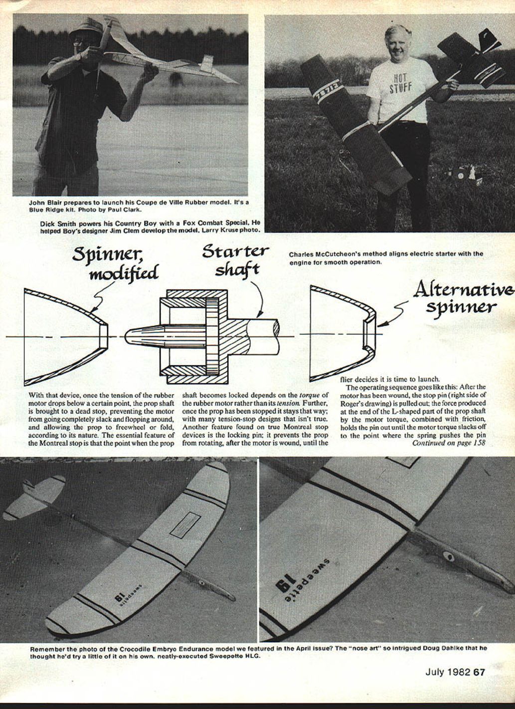
I certainly concur on the drag business; blacksmithing a spinner as an alternative would require more than a hand drill — but where there's a will...
Nats unofficial FF events
Terry Rimert, the NFFS' official Unofficial Events Director, sent the official Unofficial Events list (appearing in a separate box elsewhere in the column). Some events may apply to either or both Indoor and Outdoor contests, depending on how official Indoor events are handled. If any of these events becomes part of the official Nats events list, it will be removed from the Unofficial list.
If you want the full details — plus Rubber Power Speed model plans, rules, schedule, and a "Beat Matsunao" iron‑on for your T‑shirt — write to:
- Terry Rimert, 367 Orange Ave., Baldwin, FL 32234.
And that's official!
Another rubber winder (Gaylord 6:1)
I borrowed a Gaylord 6‑to‑1 winder (sold by Sig) for evaluation. Counting output turns versus input turns suggested it was a bit shy of 6:1. After opening the case I counted the gears: two gear pairs, each 24‑tooth driving 10‑tooth. The effective ratio is:
- 24/10 × 24/10 = 5.76
So, 5.76:1 rather than a true 6:1 — about 4% short.
Observations:
- There was grease on gear faces (not teeth); shafts and thrust washers seemed lubricated.
- A bit of Lubriplate on the gear teeth helped smooth operation.
- With some whittling, a Sig ball‑bearing thrust could possibly be fitted between the output shaft and housing — a potential upgrade but a gamble whether worthwhile.
Performance:
- Worked smoothly to the breaking point of a loop of 3/16" rubber.
- Suitable for small sport models (Peanut Scale, etc.). A higher overall ratio (10:1 or 15:1) would suit some uses better, but 5.76:1 is a substantial improvement over cheaper 4:1 winders.
Availability:
- The Gaylord winder is sold in many hobby shops and mail‑order outfits catering to free flighters. See the directory in the May and June 1981 issues.
Tri‑winglets, revisited
After my May column on winglets ("If one is good, three are better"), I asked NASA's W. Hewitt Phillips about their potential for free‑flight models. His reply, in part:
- He noted wingtip vanes similar to those I showed were tested at Cranfield, England, and proved effective in increasing effective aspect ratio (though they also increased actual aspect ratio).
- On the Morane‑Saulnier Paris jet trainer tested at Cranfield, the vanes radiated from the tip tank.
- He expressed doubt that tip‑feathers would benefit models because of low Reynolds numbers and possible interference drag, but he didn't want to discourage experimentation.
A bit of information on tip‑feathers also appeared in the final issue of the Aeromodeller Annual 1978–79 (E. F. Blick, "Bird Aerodynamics"). I'll check further.
If anything useful comes from the Novice Pennyplane prop I built incorporating prop tips, I'll be the first to report it.
Round wing‑tippers, arise!
In February I mentioned Erv Rodemsky's proposal to change the FAI World Championships Indoor rules. Discussion produced two broadly agreed points:
- Maximum span‑and‑chord rules are easier to administer than maximum area rules.
- If maximum span‑and‑chord rules are used, everybody will build rectangular‑wing models.
I agree with No. 1, and accept that No. 2 will likely be true short‑term. Our Easy B experience shows expert fliers tend to optimize around the rule and win despite imperfect details (square tips included). People copy winners and perpetuate the square‑tip syndrome.
But aerodynamically:
- Rectangular planform wings do not produce a rectangular lift distribution; their lift distribution is closer to elliptical.
- Going from an elliptical to a rectangular planform gains about 22% more area but only about 5% more lift; the extra area still adds skin‑friction drag.
- At the low Reynolds numbers of Indoor flight, skin friction is a significant penalty.
Given maximum span‑and‑chord constraints, the optimum shape is likely between elliptical and rectangular — perhaps halfway in chord distribution. Frank Zaic identified similar ideas way back in the 1930s. Most optimums are forgiving: you can miss them and not suffer much.
Other considerations:
- Twist: probably not a huge factor by itself.
- Dihedral: necessary to some extent; distribution can be a single center break, staged outboard dihedral, or other treatments.
- Winglets as originally defined: unlikely to help at low Reynolds numbers.
- A pragmatic idea: short tips with steep dihedral and a touch of washout (achieved by toeing‑out the dihedral‑break rib) — these act like small winglets and make dihedral "pay its way."
Square tips are not ideal. Given time and experimentation, designers will move away from square tips, and the experimentation will be fun and educational.
The editorial "we"
I often read things where the author says "we did this" or "we think that." That bothers me. To me, "we" reads like a share‑the‑blame gambit: if something is wrong, blame "us," not the individual. I write this column; there is no "we" involved, although I occasionally slip into the "we" syndrome myself.
It could be imagined that what I say here represents the corporate opinion of the AMA. It does not — these are my views alone.
Transcribed from original scans by AI. Minor OCR errors may remain.

