
Free Flight: Duration
Bob Meuser
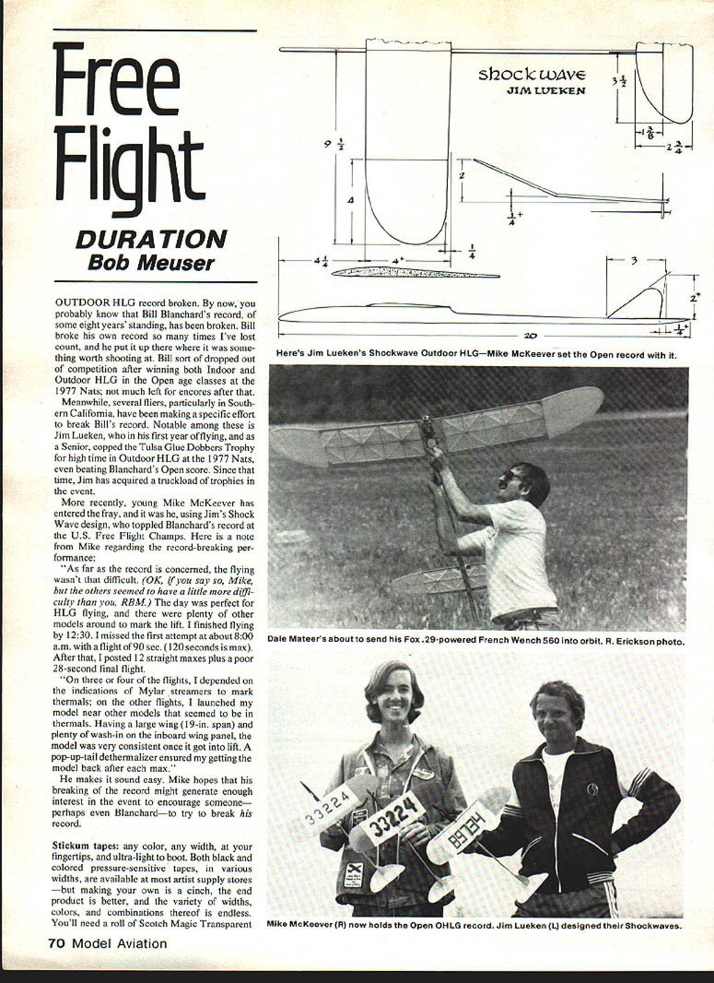
Outdoor HLG record broken
Outdoor HLG record broken. Bill Blanchard's record — some eight years standing — has been toppled. Bill broke his own record so many times it's become a benchmark; after winning both Indoor and Outdoor HLG in the Open age classes at the 1977 Nats he largely dropped out of competition.
Several fliers, particularly in Southern California, have been aiming specifically at Bill's mark. Notable among them is Jim Lueken, who in his first year of flying, as a Senior, won the Tulsa Glue Dobbers Trophy for high time in Outdoor HLG at the 1977 Nats, even beating Blanchard's Open score. Since then Jim has collected many trophies in the event.
More recently, Mike McKeever entered the fray and, using Jim's Shock Wave design, broke Blanchard's record at the U.S. Free Flight Championships. Mike described the record-breaking day:
"As far as the record is concerned, the flying wasn't that difficult. The day was perfect for HLG flying, and there were plenty of other models around to mark the lift. I finished flying by 12:30. I missed the first attempt at about 8:00 a.m. with a flight of 90 sec. (120 seconds is max). After that, I posted 12 straight maxes plus a poor 28-second final flight.
"On three or four of the flights, I depended on the indications of Mylar streamers to mark thermals; on the other flights, I launched my model near other models that seemed to be in thermals. Having a large wing (19‑in. span) and plenty of wash‑in on the inboard wing panel, the model was very consistent once it got into lift. A pop‑up‑tail dethermalizer ensured my getting the model back after each max."
Mike hopes his achievement will generate enough interest in the event to encourage challengers — perhaps even Blanchard — to try to break the new record.
Stickum tapes (making colored pressure‑sensitive tapes)
Stickum tapes — any color, any width, ultra‑light — are useful and easy to make. Artist‑supply stores sell black and colored pressure‑sensitive tapes in various widths, but making your own gives better end results and endless color/width combinations.
Materials:
- Scotch Magic Transparent Tape (or similar)
- A piece of glass or Formica-type flat surface
- Single-edge razor blade
- Metal straightedge
- Spray-can enamel in the color of your choice
Procedure:
- Stick strips of the transparent tape onto the glass.
- Stand back and spray with enamel. Glass lets you judge paint-film thickness by transmitted light.
- After drying, use the razor blade and straightedge to slice the painted tape into strips of your preferred widths.
Paint notes:
- For flat colors use Pactra Scale Model Flats; for glossy use regular Pactra colors (available at model-railroad-supply outlets).
- If a desired color is only available glossy but you want flat, overspray with a flat transparent coat.
- If you have a model spray gun and don't mind cleanup, consider buying bottles of paint rather than spray cans.
Pelegi world‑record helicopter revisited
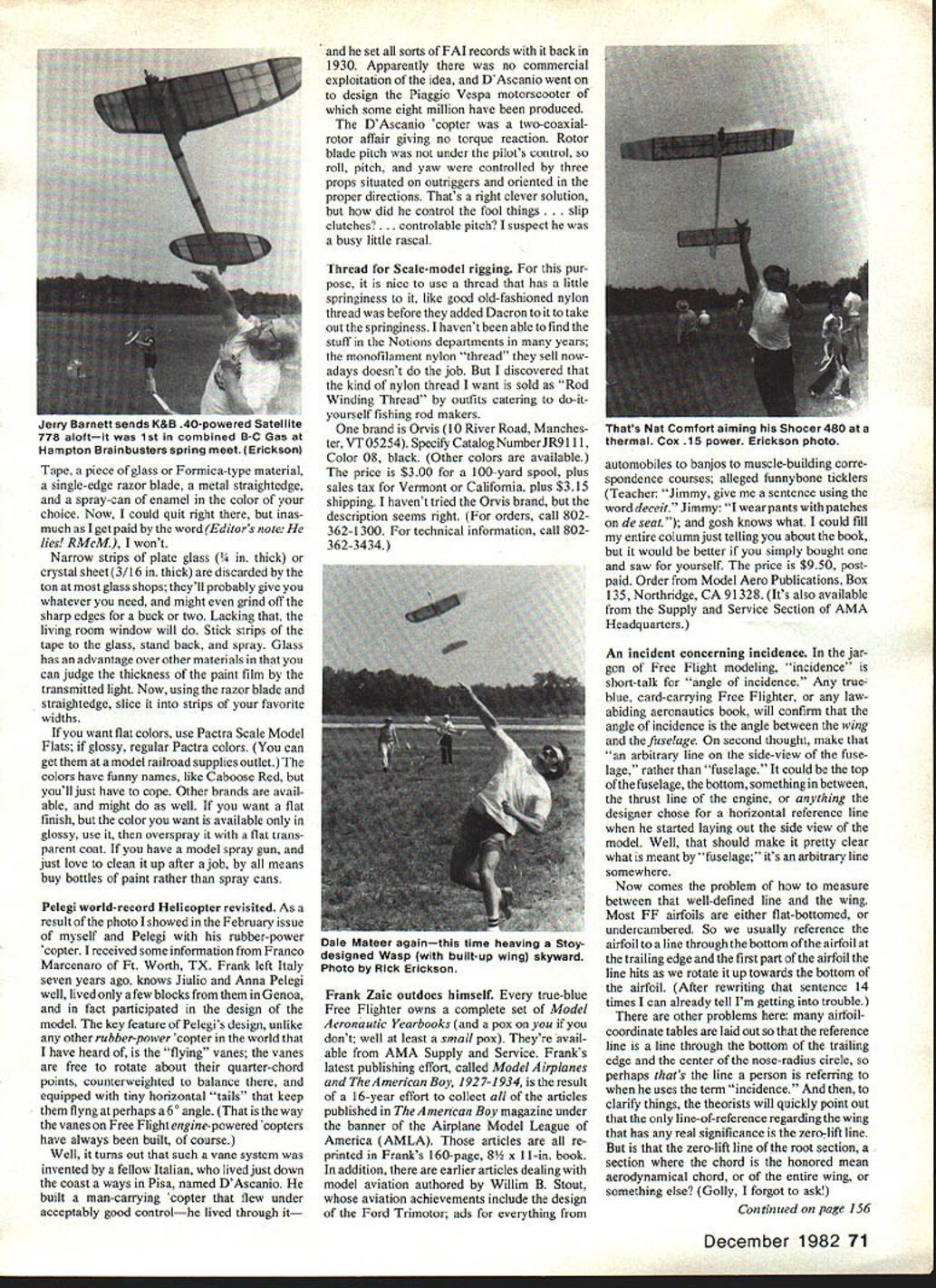
Following a photo in a previous issue of Pelegi with his rubber‑power 'copter, Franco Marcenaro of Ft. Worth, TX, supplied background. Marcenaro (who left Italy seven years ago) knows Giulio and Anna Pelegi and helped design the model. The key feature of Pelegi's design is the "flying" vanes: the vanes are free to rotate about their quarter‑chord points, counterweighted to balance there, and fitted with tiny horizontal tails that keep them flying at about a 6° angle. (This vane arrangement resembles how vanes on free‑flight engine‑powered copters have traditionally been built.)
Marcenaro pointed out that a similar vane system was invented by an Italian named D'Ascanio in Pisa. D'Ascanio built a man‑carrying 'copter in the 1930s, set several FAI records, and later designed the Piaggio Vespa motorscooter. His 'copter used two coaxial rotors to avoid torque reaction; rotor blade pitch was not pilot‑controlled, so roll, pitch, and yaw were handled by three small props on outriggers. It was an ingenious early solution.
Thread for scale‑model rigging
For rigging, it's helpful to use a thread with a bit of springiness — like the old nylon thread before Dacron was added. The current monofilament "threads" sold in Notions departments often lack this spring. A good substitute is "Rod Winding Thread" sold to do‑it‑yourself fishing‑rod makers.
One source:
- Orvis (10 River Road, Manchester, VT 05254)
- Catalog number: JRJ111
- Color: 08 (black) — other colors available
- Price: $3.00 for a 100‑yard spool (plus sales tax where applicable) and $3.15 shipping
- Order phone: 802‑362‑1300
- Technical info: 802‑362‑3434
I haven't personally tried the Orvis brand, but the description matches the thread desired.
Frank Zaic's publication
Every Free Flighter should own the Model Aeronautics Yearbooks. Frank Zaic's latest book, Model Airplanes and The American Boy, 1927–1934, is the result of a 16‑year effort to collect all articles published in The American Boy magazine under the Airplane Model League of America (AMLA). The 160‑page (8½ x 11 in.) volume reprints those articles and includes earlier model‑aviation pieces by William B. Stout, numerous period ads, and other contemporaneous material.
Price: $9.50 postpaid. Order from: Model Aero Publications, Box 135, Northridge, CA 91328. (Also available from the Supply and Service Section of AMA Headquarters.)
An incident concerning incidence
In Free Flight jargon, "incidence" is short for "angle of incidence." Commonly, it's described as the angle between the wing and the fuselage — but that is ambiguous unless you define the reference line on the fuselage. The fuselage reference might be the top, the bottom, the thrust line, or any arbitrary side‑view line chosen by the designer.
Similarly, defining the wing reference line can be tricky. Many FF airfoils are flat‑bottomed or undercambered, so modelers often reference the airfoil to a line through the bottom of the trailing edge and the first point the line hits as it's rotated up toward the nose. Some coordinate tables use a line through the bottom of the trailing edge and the center of the nose‑radius circle. Theorists note that the only wing reference with physical significance is the zero‑lift line — but then you must decide whether that's the root section zero‑lift line, a mean aerodynamic chord zero‑lift line, or something else.
In practice, "incidence" has also been applied to the horizontal tail, which breeds confusion. For example, if a tail is set at −1°, does "increasing the incidence" mean making it more negative (e.g., −2°) or less negative (e.g., 0°)? Some modelers use "incidence" to mean the difference in angle between the wing and the tail. If the foremost surface (wing or canard) has a greater angle than the rearward surface, the incidence is positive and the aircraft will tend to loop more as incidence increases.
Historically, the term decalage referred to the difference in angle between wing and tail. Prior to about 1915 the NACA defined decalage that way; later decalage became used for the difference between upper and lower wings of biplanes. "Longitudinal dihedral" was sometimes used for the wing‑to‑tail difference.
For clarity, I strongly urge the Free Flight community to:
- Use "incidence" only for the wing (relative to a clearly defined fuselage reference line).
- Use "decalage" to describe the difference in angle between the wing and the tail.
This preserves precision and avoids the ambiguities that currently confuse modelers and theorists alike.
Transcribed from original scans by AI. Minor OCR errors may remain.

