
Free Flight: Duration
Bob Meuser
'COPTER CAPERS: Awhile back, when Outdoor Rubber-Power Helicopter was added to the Nats program as an unofficial NFFS-sponsored event, I got to scratching my head about the problem.
Outdoor helicopters, for some 40 years, have employed twin fixed-pitch rotors revolving in opposite directions. When the rubber unwinds, they fall out of the sky. The record was set with an ultra-lightweight indoor type 'copter. Somehow that didn't seem like the right way to do the job. Outdoor models should glide and catch thermals and get lost, and such.
How do you make a 'copter glide? . . . or autorotate? The gas-powered 'copter lads figured that out decades ago. The vanes, rather than being fixed, are pivoted in such a way as to let them seek the proper angle of attack, depending on the motor torque. This includes zero torque—autorotation. The vanes have horizontal tails and nose weights, and are pivoted at their CG's. In effect, each vane is a complete glider that is towed around in a circle by the hub, or constrained by the hub to glide around in a circle.
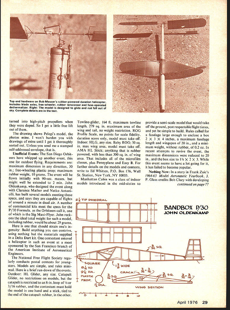
My chopper was to have two four-blade rotors, motor tensioner, free-wheel device, and, of course, a dethermalizer, which was to be a fuse-actuated device to prevent relative rotation of the rotors. The hardware was built, but the necessity of having to build eight stick-and-tissue vanes relegated the project to the back burner. About then I received a copy of the Italian magazine Modellistica showing Giulio Pelegi's model that had set world records for distance (17,200 ft.), altitude (1,962 ft.), and an Italian national record for duration (28 min. 45 sec.).
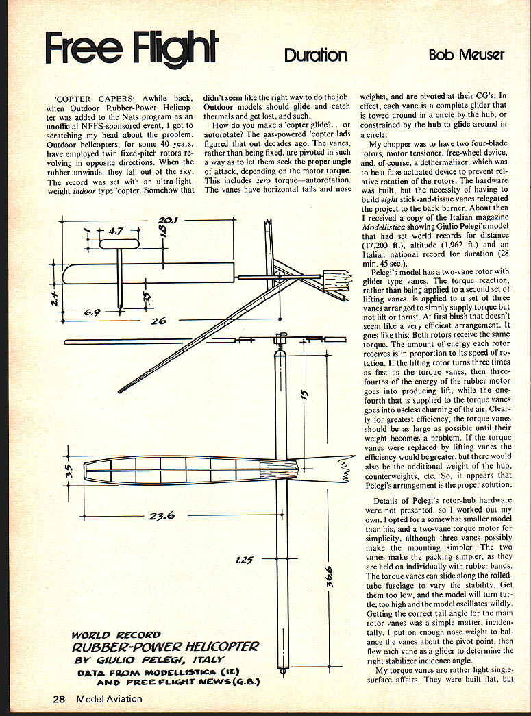
Pelegi's model has a two-vane rotor with glider type vanes. The torque reaction, rather than being applied to a second set of lifting vanes, is applied to a set of three vanes arranged to simply supply torque but not lift or thrust. At first blush that doesn't seem like a very efficient arrangement. It goes like this: Both rotors receive the same torque. The amount of energy each rotor receives is in proportion to its speed of rotation. If the lifting rotor turns three times as fast as the torque vanes, then three-fourths of the energy of the rubber motor goes into producing lift, while the one-fourth that is supplied to the torque vanes goes into useless churning of the air. Clearly for greatest efficiency, the torque vanes should be as large as possible until their weight becomes a problem. If the torque vanes were replaced by lifting vanes the efficiency would be greater, but there would also be the additional weight of the hub, counterweights, etc. So, it appears that Pelegi's arrangement is the proper solution.
Details of Pelegi's rotor-hub hardware were not presented, so I worked out my own. I opted for a somewhat smaller model than his, and a two-vane torque motor for simplicity, although three vanes possibly make the mounting simpler. The two vanes make the packing simpler, as they are held on individually with rubber bands. The torque vanes can slide along the rolled-tube fuselage to vary the stability. Get them too low, and the model will turn turtle; too high and the model oscillates wildly. Getting the correct tail angle for the main rotor vanes was a simple matter, incidentally. I put on enough nose weight to balance the vanes about the pivot point, then flew each vane as a glider to determine the right stabilizer incidence angle.
My torque vanes are rather light single-surface affairs. They were built flat, but turned into high-pitch propellers when they were doped. So I get a little free lift out of them.
The drawing shows Pelegi's model, the photos mine. I won't burden you with drawings of mine until I get it thoroughly sorted out. Unless you send a stamped self-addressed envelope, that is.
Unofficial Events: The San Diego Orbiters have whipped up another event, this one for outdoor flying. Requirements are: maximum dimension in any direction, 30 in.; free-wheeling plastic prop; maximum rubber weight, 10 grams. The event will be flown initially with 90-sec. maxes, but might well be extended to 2 min. John Oldenkamp, who designed the event along with Clarence Mather and Natko Antoniolli, has built several models meeting these specs, and says they are capable of flights of around a minute in dead air. A number of commercial kits meet the specs for the P/30 Formula, as the Orbiteers call it, one of which is the Sig Maxi-Flyer. John reckons the ideal total weight for such a model, including rubber, would be about 29 grams.
Here is one that should strain one's ingenuity: Build anything you can contrive, using nothing but the materials supplied in a Delta Dart kit. One contestant entered a helicopter in such an event at a meet sponsored by the San Francisco branch of the American Institute of Aeronautical Engineers.
The National Free Flight Society regularly conducts postal contests for youngsters. Models are simple, and rules minimal. Here is a brief run-down of the events.
Outdoor: HL Glider, any size. Catapult Glider, no restrictions on models, but the catapult is restricted to an 8-in. loop of 1/8 or 3/16 rubber, and the contestant must hold the model in one hand and a stick, tied to the end of the catapult rubber, in the other.
Towline-glider, 164 ft. maximum towline length, 279 sq. in. maximum area of the wing and tail, no weight restriction. ROG Profile Scale, no points for scale fidelity, duration score only, model must take off.
Indoor: HLQ, any size. Baby ROG; 30 sq. in. max wing area, model must take off. AMA HL Stick; anything that is rubber powered, with less than 300 sq. in. of wing area. That includes all of the microfilm classes, plus Pennyplane and Easy B. For further details on the models and contests, write to Ed Whitten, P.O. Box 176, Wall St. Station, New York, NY 10005.
Manhattan Cabin was a class of indoor models introduced in the mid-sixties to provide a semi-scale model that would take off the ground, post respectable flight times, and yet be simple to build. Rules called for a fuselage large enough to enclose a box 2 x 3 x 4 inches, a maximum fuselage length and wingspan of 20 in., and a minimum weight, without rubber, of 0.2 oz. In attempts to revive the event, the maximum dimensions were reduced to 20 in., and the box size to 1 1/4 x 2 x 3. While this event seems to have a lot going for it, it has failed to become popular.
Nothing New: In a story in Frank Zaic's 1964-65 Model Aeronautic Yearbook, J. P. Glass credits Bob Clary with developing...
Free Flight: Duration
the first microfilm for use as a model covering material. But thin plastic films that would qualify under the definition of microfilm were used at least as early as 1891, and probably a lot earlier, for other purposes.
In the "new and enlarged edition of 1911" of the delightful book, Soap Bubbles, Their Colours and the Forces Which Mould Them, the author C. V. Boys quotes from a letter from a "Mr. Glew" (no pun intended) describing microfilm made 20 years earlier which "shewed no change" in all that time. Mr. Glew's formula was "...celluloid dissolved in amyl acetate, 8 grains to the ounce," whatever that is. He boiled it a few minutes, cautioning the reader to its flammability, to drive off moisture, ensuring clear unclouded films. "The drops of the solution should fall about 1 1/2 inches above the surface of the water, or the drops may roll about on the air-film and so delay spreading. Black (extremely thin) films may be raised 2 or 3 inches in diameter," and he obtained colored films over a foot in diameter. According to Mr. Glew: "Lord Rayleigh has made use of the films for enclosing various gases..."
J. P. Glass describes Bob Clary's experimental procedure. "His method consisted of continuing to add every imaginable kind of thing to a quart or two of dope," and he likens the result to something brewed by Shakespeare's Macbeth witches, or Al Capp's Kickapoo Joy Juice works.
Low-Ceiling Hand-Launch Gliders: For most types of free-flight models—indoor, outdoor, regardless of motive power—still-air duration will be improved by moving the center-of-gravity back to the point where longitudinal stability becomes a problem. Flying in turbulent air favors a more forward CG position, but that's another story. It comes as a bit of a shock to find that this time-honored maxim does not apply, apparently, to low-ceiling indoor HLG flying.
Awhile back, Ron Wittman, writing in Indoor News and Views, reported some experimenting he had done with his Tara 16. Mind you, this model had already been trimmed well enough to have set the Category I record, and held it for a respectable period of time, before Ron started messing around with it. Ron started adding weight to the nose, and adding "up" to the trailing edge of the stabilizer, and found that the flight time improved continuously until he was getting times of 34 sec., which isn't half bad with a 20-foot ceiling. Ron's flying companion Bob Gibbs tried the same procedure on his own glider, and achieved the same results. When I first read the story, I figured I must be misinterpreting the whole thing, but upon checking with both Ron and Bob I found Ron meant exactly what he said.
More recently, Bob Klipp, Editor of The Turbulator, reported some pretty good low-ceiling IHLG flight times made by Dick Hardcastle, and subsequent correspondence with Dick turned up some interesting information. Dick ties HLG a lot, but he is not really a HLG nut; he uses it to while away the time until the serious stuff starts—Easy B, and the like.
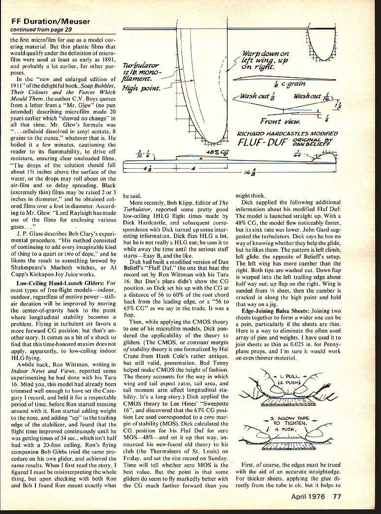
Dick had built a modified version of Dan Braddock's "Fluf Duf," the one that beat the record set by Ron Wittman with his Tara 16. But Dan's plans didn't show the CG position, so Dick set his up with the CG at a distance of 56 to 60% of the root chord back from the leading edge, or a "56 to 65% CG" as we say in the trade. It was a flop.
Then, while applying the CMOS theory to one of his microfilm models, Dick pondered the applicability of the theory to gliders. (The CMOS, or constant margin of stability theory is one formalized by Hal Crane from Hank Cole's rather antique, but still valid, presentation. Bud Trench helped make CMOS the height of fashion.) The theory accounts for the way in which wing and tail aspect ratio, tail area, and tail moment arm affect longitudinal stability. It's a long story.) Dick applied the CMOS theory to Lee Kline's "Sweepeetie 16", and discovered that the 63% CG position Lee used corresponded to a zero margin of stability (MOS). Dick calculated the CG position for his Fluf Duf for zero MOS—48%—and set it up that way, announcing his new-found old theory to his club (the Thermalers of St. Louis) on Friday, and set the site record on Sunday. Time will tell whether zero MOS is the best value. But the point is that some gliders do seem to fly markedly better with the CG much farther forward than you might think.
Dick supplied the following additional information about his modified Fluf Duf: The model is launched straight up. With a 48% CG, the model flew noticeably faster, but its sink rate was lower. John Gard suggested the turbulators. Dick says he has no way of knowing whether they help the glide, but he likes them. The pattern is left climb, left glide; the opposite of Belieff's setup. The left wing has more camber than the right. Both tips are washed out. Down flap is warped into the left trailing edge about halfway out; up flap on the right. Wing is sanded from 1/2 sheet, then the camber is cracked in along the high point and held that way on a jig.
Edge-Joining Balsa Sheets: Joining two sheets together to form a wider one can be a pain, particularly if the sheets are thin. Here is a way to eliminate the often used array of pins and weights. I have used it to join sheets as thin as 0.025 in. for Pennyplane props, and I'm sure it would work on even thinner material.
First, of course, the edges must be true with the aid of an accurate straightedge. For thicker sheets, applying the glue directly from the tube is ok, but it helps... slot the plastic nozzle slightly wider than the thickness of the sheet. For thin sheets, I prefer the following procedure: Run out a bead of glue along the work bench, smooth it to a uniformly thin thickness with a balsa scrap, and dip the edge of the sheet into it. Then comes the magic.
The inherent elasticity of masking or drafting tape is used to supply the clamping force. After applying the glue, place the sheets together edge-to-edge over a strip of Saran Wrap. Tear off a piece of tape that is a bit wider than the total width of the sheets. Stretch the tape between the thumbs, and press the sticky side onto the sheet a short distance from the joined edges. Then relax the pull on the tape, and the tape will pull the joint tight. Finally, pull the ends of the tape over the outer edges of the sheet, and stick them to the workboard. Repeat at appropriate intervals along the joint.
For joining wide sheets, you might prefer to use short strips of tape and weights to hold the joint flat while the glue sets. For thicker sheets, apply the tape to both sides of the joint.
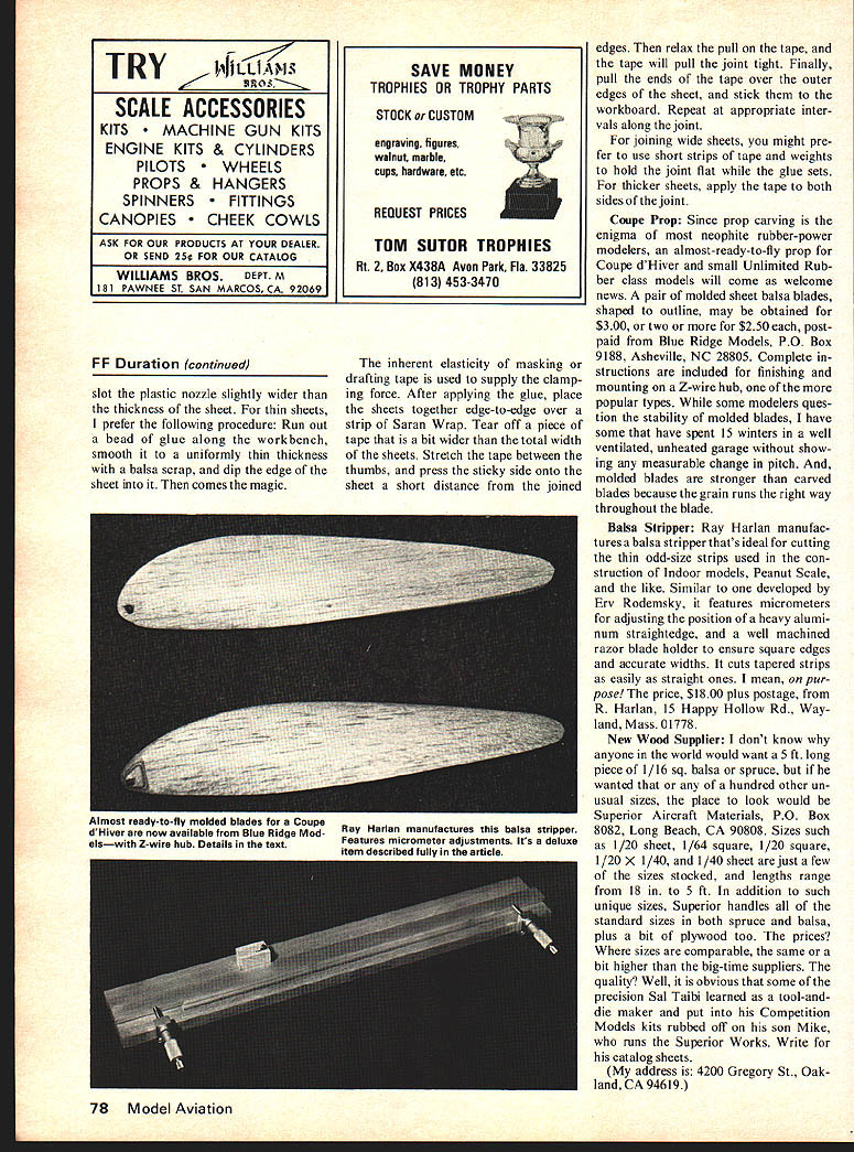
Coupe Prop: Since prop carving is the enigma of most neophyte rubber-power modelers, an almost-ready-to-fly prop for Coupe d'Hiver and small Unlimited Rubber class models will come as welcome news. A pair of molded sheet balsa blades, shaped to outline, may be obtained for $3.00, or two or more for $2.50 each, postpaid from Blue Ridge Models, P.O. Box 9188, Asheville, NC 28805. Complete instructions are included for finishing and mounting on a 2-wire hub, one of the more popular types. While some modelers question the stability of molded blades, I have some that have spent 15 winters in a ventilated, unheated garage without showing any measurable change in pitch. And, molded blades are stronger than carved blades because the grain runs the right way throughout the blade.
Balsa Stripper: Ray Harlan manufactures a balsa stripper that's ideal for cutting the thin odd-size strips used in the construction of Indoor models, Peanut Scale, and the like. Similar to one developed by Rev Rodensky, it features micrometer adjustments for adjusting the position of a heavy aluminum straightedge, and a well machined razor blade holder to ensure square edges and accurate widths. It cuts tapered strips as easily as straight ones. I mean, on purpose! The price, $18.00 plus postage, from R. Harlan, 15 Happy Hollow Rd., Wayland, Mass. 01778.
New Wood Supplier: I don't know why anyone in the world would want a 5 ft. long piece of 1/16 sq. balsa or spruce, but if he wanted that or any of a hundred other unusual sizes, the place to look would be Superior Aircraft Materials, P.O. Box 8082, Long Beach, CA 90808. Sizes such as 1/20 sheet, 1/64 square, 1/20 x 1/40, and 1/40 sheet are just a few of the sizes stocked, and lengths range from 18 in. to 5 ft. In addition to such unique sizes, Superior handles all of the standard sizes in both spruce and balsa, plus a big assortment of plywood too. The prices? Where sizes are comparable, the same or a bit higher than the big-time suppliers. The quality? Well, it is obvious that some of the precision Sal Taibi learned as a tool-and-die maker have put into his Competition Models kits rubbed off on his son Mike, who runs the Superior Works. Write for his catalog sheets. (My address is: 4200 Gregory St., Oakland, CA 94619.)
Transcribed from original scans by AI. Minor OCR errors may remain.

