
Free Flight
DURATION
Bob Meuser
In the lead item in my January 1984 column, titled "Strange configuration," I presented the "joined-wing" concept, although I didn't call it that, invented by Dr. Julian Wolkovitch. Shortly after publication of that issue (and before my copy arrived) I received a phone call from Dr. Wolkovitch, and later a copy of a letter addressed to the Editor, taking me to task for many aspects of my presentation. Dr. Wolkovitch's letter follows:
Letter from Dr. Julian Wolkovitch
December 4, 1983
Gentlemen,
Has your life ever been changed by a magazine article? Bob Meuser's account of my patented joined-wing configuration (Model Aviation, January 1984) spelled my name incorrectly, moved my residence from California to Ohio, and inducted me into the Air Force! Worse yet, almost every technical statement in the article was misleading or wrong. Because NASA, the U.S. Navy and several universities and aircraft manufacturers are conducting extensive research on the joined wing, which promises to be aerodynamically and structurally superior to conventional wings, I must correct the most serious errors in Mr. Meuser's article.
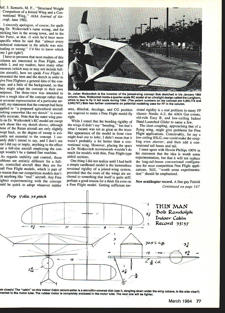
The wind tunnel tests on the agricultural airplane design were done by NASA (not the Air Force) and showed excellent aerodynamic characteristics. The NASA test report (Ref. 1) predicts no problems at full scale. (This design, by Burt Rutan, hasn't been built full-scale because we couldn't agree on the patent royalties, not because of technical objections.) Bob Meuser's drawing is inaccurate: the airplane has unswept outer wings and a thick fin containing the pilot, as shown in photos published in Aviation Week (Ref. 2).
Joined wings have been shown to be lighter and stiffer than conventional wing/tail systems (Ref. 3), provided the spars are located near the upper leading edge and lower trailing edge. As explained in my U.S. Patent No. 4,365,773, this gives them the depth to resist loads acting perpendicular to the structural truss formed by the wings.
Several joined-wing models have flown. With proper airfoil design (washout on the front wing, washin on the rear wing) these show good stability and control. The attached photo illustrates a quarter-scale model of an ultralight, the Longhorn, which will fly in full-scale form in 1984. If Bob Meuser would like to visit me (in Palos Verdes, CA, not Dayton, OH), I would be glad to demonstrate to him that this joined-wing model has exceptional flying qualities, including aileron-only turns, a flat glide, and safe stall/spin characteristics. No joined-wing model kits or plans are yet available, but readers who experiment with simple sheet balsa models following the principles explained in the references cited should be able to design their own joined-wing airplanes.
Sincerely, Dr. Julian Wolkovitch
References:
- Ref. 1 White, E. R., Low-Speed Wind Tunnel Test on a Joined-Wing Agricultural Aircraft Model. NASA Langley Research Center Report to be published 1984.
- Ref. 2 "Joined Wing Aircraft Planned for Agricultural Applications," Aviation Week, February 15, 1982, pp. 144–145.
- Ref. 3 Samuels, M. F., Structural Weight Comparison Joined Wing—Conventional Wing, AIAA Journal, June 1982.
Author's response
I sincerely apologize, of course, for spelling Dr. Wolkovitch's name wrong, for placing him in the wrong town, and for implying he was in the Air Force. I would like to know which technical statements Dr. Wolkovitch considered misleading or wrong; he'd said "almost every technical statement" was in error, and I'd like to know what, if anything, I got right.
I must presume that most readers of this column are interested in Free Flight. While I, and my readers, have many other interests (which may or may not include full-size aircraft), here we speak Free Flight. I presented the item and the sketch to give Free Flighters a general idea of the concept and a little of the background so that they might adapt the concept to their own purposes. The three-view was intended to give a rough idea of the concept rather than an accurate representation of a particular aircraft.
My statement that the concept had been applied to "a proposed agricultural aircraft looking somewhat like my sketch" is essentially accurate. Note that the outer wing panels on Dr. Wolkovitch's R/C model are swept back about like my sketch shows, although those of the Rutan aircraft are only slightly swept back, so the degree of sweep is evidently not essential to the concept. I certainly didn't intend to say, and I don't see that I did say or imply, that a full-size aircraft employing the concept wouldn't be a darned fine machine.
As regards stability and control, these problems are entirely different for a full-size, controlled aircraft than they are for small Free Flight models, which is part of the reason that our competition models don't look anything like "real" aircraft. Any Free Flight experiment with the concept would quickly adopt whatever rudder area, dihedral, decalage, and CG position are required to make a Free Flight model fly right.
While I stated that the bending rigidity of the wings (I didn't say "bending," but that's what I meant) was not as great as the truss-like nature of the model in front view might lead one to infer, I didn't mean that it wasn't probably a lot better than a conventional wing. However, placing the spars as Dr. Wolkovitch recommends wouldn't do much for models with thin, Free Flight-type airfoil sections.
One thing I did not realize until I had built a simple cardboard model is the tremendous torsional rigidity of a joined-wing system, provided that the roots of the wings are anchored to something that itself is quite stiff—perhaps a good reason for a thick fin even on a Free Flight model. Getting sufficient torsional rigidity is a real problem in many F/F classes: Nordic A-2, the AMA Gas events, old-rule Easy B, and low-ceiling Indoor Hand-Launched Glider, to name a few.
The short coupling, approaching that of a flying wing, might give problems for Free Flight applications. Conceivably, for a low-ceiling IHLG one could make the coupling even shorter, and then add a conventional tail boom and tail.
I must agree with Hewitt Phillips 100% in his statement that the idea is worth some experimentation, but that it will not replace the long-tailboom conventional configuration for most competition Free Flight applications. Still, "worth some experimentation" should be emphasized.
Postscript: Thin Man (unrelated note)
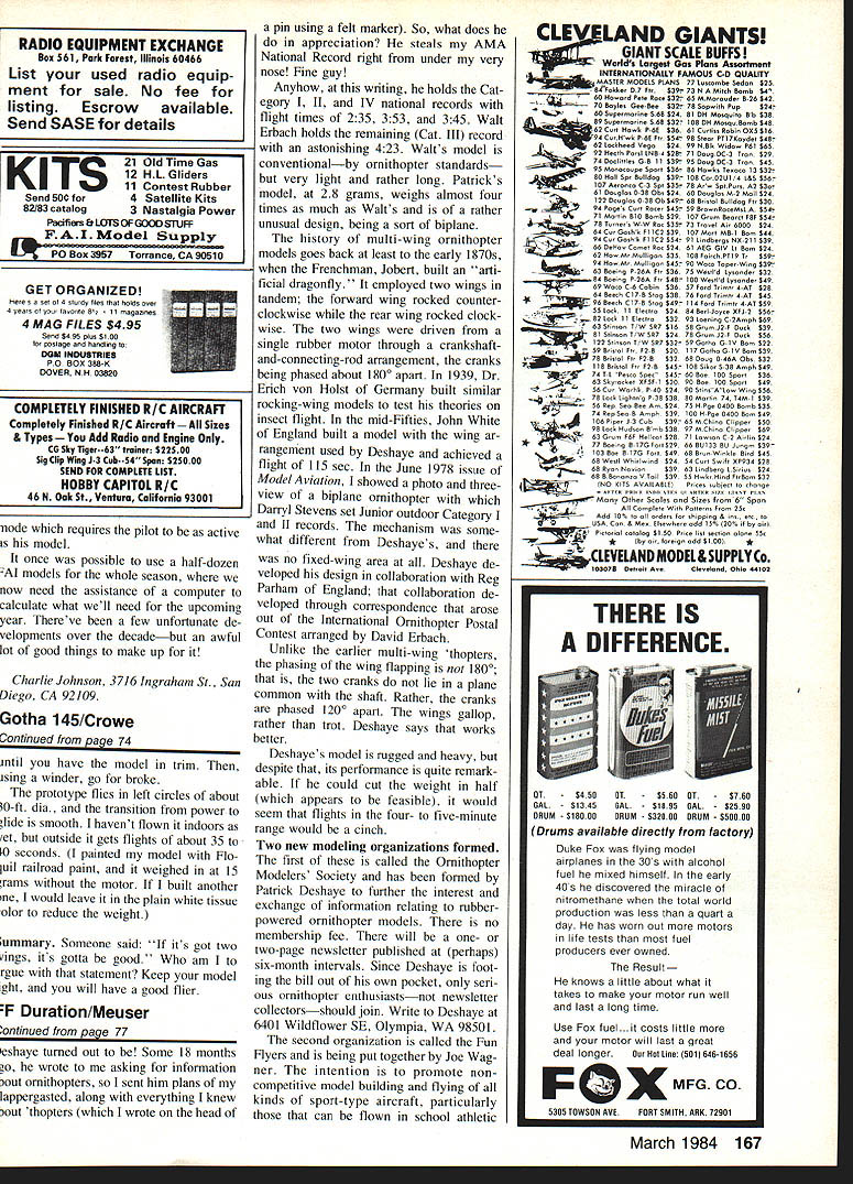
Be built much lighter. Thus the Thin Man was born, and it came out with a total weight of only 0.00325 oz. I had intended doing comparative tests using a double-cone pod, but the model with the disc flew very well, setting the record on its third flight. Then I was fortunate enough to win the FAI Team Selection Finals, and so I have had to concentrate on preparations for the World Champs. Additional Cabin-model development will have to wait. I'm sure that, with the use of more boron filament, I could get the weight down even more.
You have to read the rule book rather closely to figure out how the Thin Man qualifies as a Cabin model, but it does. The rubber motor is enclosed in a balsa tube, to which the disc is attached. The disc is covered on both sides with microfilm with a tiny balsa spool separating the two surfaces. The rules require that a Cabin model have a "built-up, enclosed fuselage," and it is a little hard to see how a balsa tube qualifies as a built-up, enclosed fuselage. However, a lot of Cabin models have been built that way, so it is probably OK.
Bob Meuser 4200 Gregory St., Oakland, CA 94619.
Transcribed from original scans by AI. Minor OCR errors may remain.

