
Free Flight: Indoor
Bud Tenny
TRULY COMPETITIVE activity in any kind of model flying requires careful attention to detail, but this is especially true with indoor models. Each time a model is flown, things must be exactly right for the model to give its best performance. Is the wing incidence right? A tiny fraction of one degree change in incidence will make a noticeable difference in performance, yet 1/16 in. change in incidence is only one degree for a wing 3½ in. wide. If you change props on your super FAI ship, does the new prop weigh the same as the old one? A change in prop weight on the average FAI indoor model will shift the center of gravity about ¼ in. for each .001 oz. of weight change! Does that explain why the "super" model suddenly started flying like a lead sled?
Check List: Every time your model is flown, there are many things that should be carefully checked before flight or before leaving home:
- Are there repairs to be made as a result of previous flying sessions?
- Assemble the model completely and examine the washin/washout, stab tilt and rudder setting. "Bounce" the model lightly by moving it up and down enough to stress the bracing slightly; look for changes in wing alignment and loose wires.
- Locate and repair even tiny holes in the microfilm, especially in the prop.
- Check the thrust bearing and rear hook to be sure all is secure — these parts take terrific stress under full turns.
- Be sure the wing incidence is correct; if several models are in the same box, be sure the proper parts get together, and that you have the prop you planned.
- Be sure you have the intended rubber motor; if making new motors, be sure which size and batch of rubber is used as a source.
- Know how much power (torque) is needed when flying in restricted ceilings, both to maximize performance and to prevent hangups or model damage.
- When making flight trim adjustments, change only one thing at a time and keep appropriate records to verify performance changes.
Built-in Reliability:
The flier who wins a lot probably has a reliable model which is well trimmed and thoroughly checked. A number of building and design practices help to create reliable models which seldom need changes in trim:
- Wing sockets should have a balsa plug in the bottom so the wing posts can "bottom out" against the plugs. Change wing incidence by cutting tiny pieces off the end of the post (use fingernail clippers) and always push the post all the way in. The post should be a snug fit in the socket to prevent flight loads from pulling the post out of the socket.
- Always be sure the wing sockets are parallel to each other so the wing has the same washin/washout on the model as on the bracing jig and on the packing jig which holds the wing in the storage box. The bottom end of the socket must be glued to the motorstick, or the wing will shift around in flight.
- The wing posts and cabane must be strong enough to handle flight and ground handling loads. Otherwise, the model will be inconsistent and
4) Use adequate reinforcement around the thrust bearing and have adequate clearance between the motorstick and the motor. Full-power hookups severely stress the front of the motorstick, and rubbing knots kill the climb and/or wreck the stick by rubbing through the wood.
5) Color-code the parts for each model, including the prop. If different props are used on the same model, be sure each prop weighs the same as others. Mark props to identify the pitch, if different pitch props are used.
6) Keep careful records of model performance, with enough detail to be able to repeat good performances.
7) If possible, test each batch of rubber and keep track of each motor by using small marked envelopes. Be sure to return each motor to its "home" after use. If different batches vary widely in quality, it is important to know which kind of rubber you are using. It is possible to allow for crummy rubber, but a motor of unknown quality is sure to give a nasty surprise.
8) Build and fly any particular design enough to learn its strengths and weaknesses. Take care to make each successive model of a design as identical as possible to previous models; use patterns and templates to insure uniformity. Keep records of component weights to guide future decisions on building, but remember that any structure too light to hold its shape properly will contribute to inconsistent performance.
9) Be aware of the relationship between the model's center of gravity and the center of the motor. If these two points are very far apart, changing the weight of rubber will cause the model's center of gravity to shift.
Model Assembly Jigs:
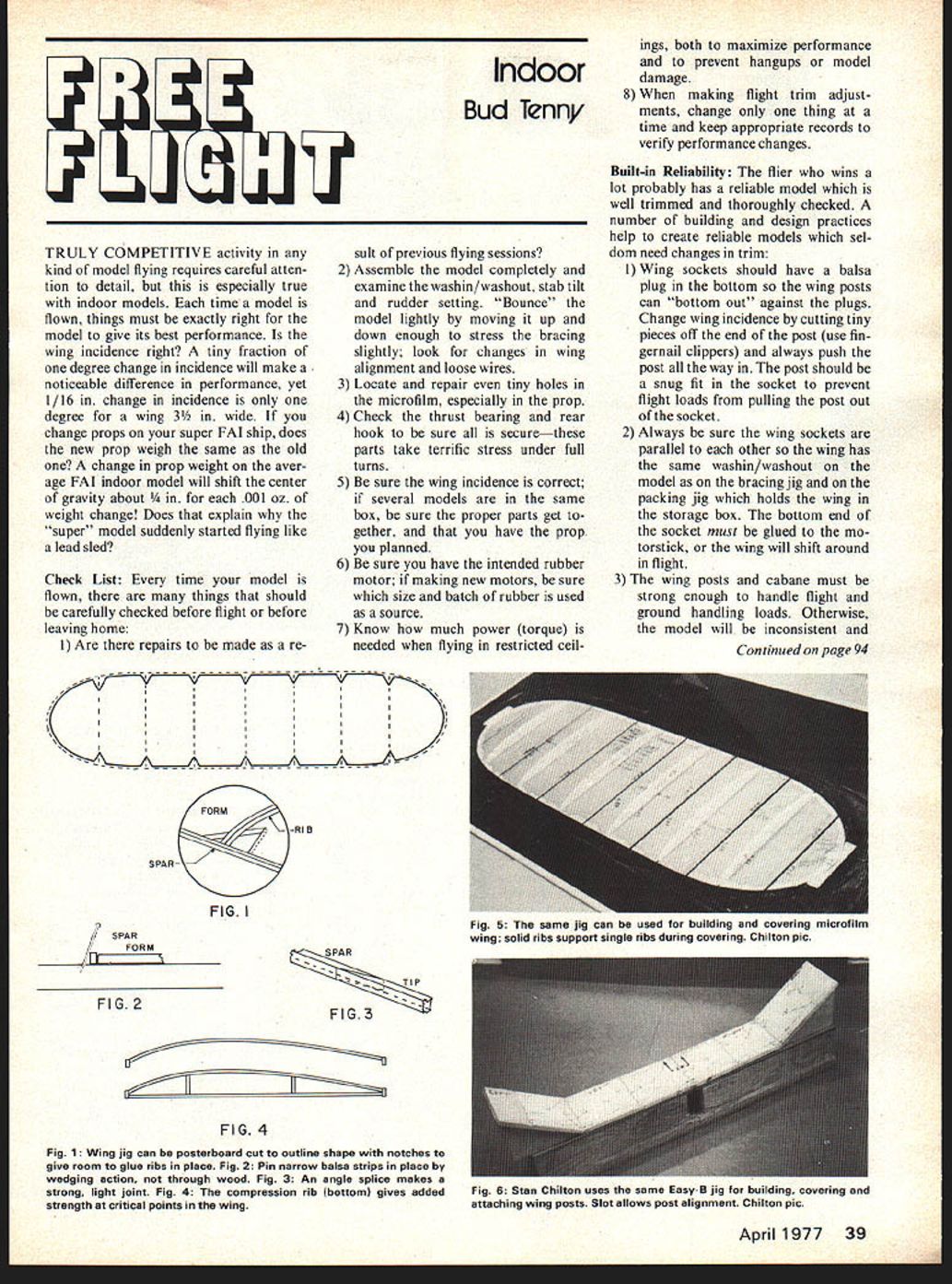
The most basic indoor model jig after the prop block (covered in previous columns) is the wing or stab outline jig. In its simplest form, the outline jig is thin cardboard or posterboard cut just small enough to fit inside the wing or stab outline (Fig. 1). Notches cut in the perimeter give clearance for ribs to attach to the outline (expanded view in Fig. 1). Careful work then allows each wing or stab to be essentially identical to the previous ones, except for chance or intentional variations in wood thickness or grade. To use the form, first shape the curved portions of the outline by wrapping moist balsa strips of the proper size around an identically shaped tip form and baking them in the oven set to low heat. Straight portions of the outline are laid in place with straight pins holding them against the form. Fig. 2 shows how delicate strips are held in place—never pin through the wood. Use an angle splice (Fig. 3) to join the curved portions to the straight sections, using care to avoid gluing the strips to the form. Finally, ribs are cut to exact length and glued in place.
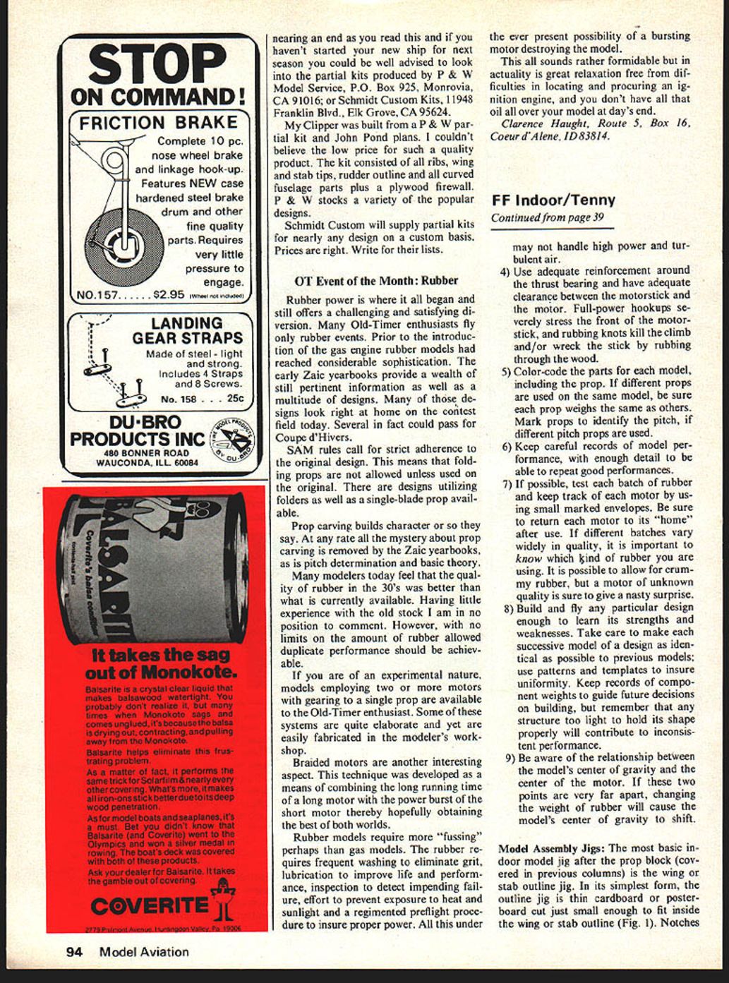
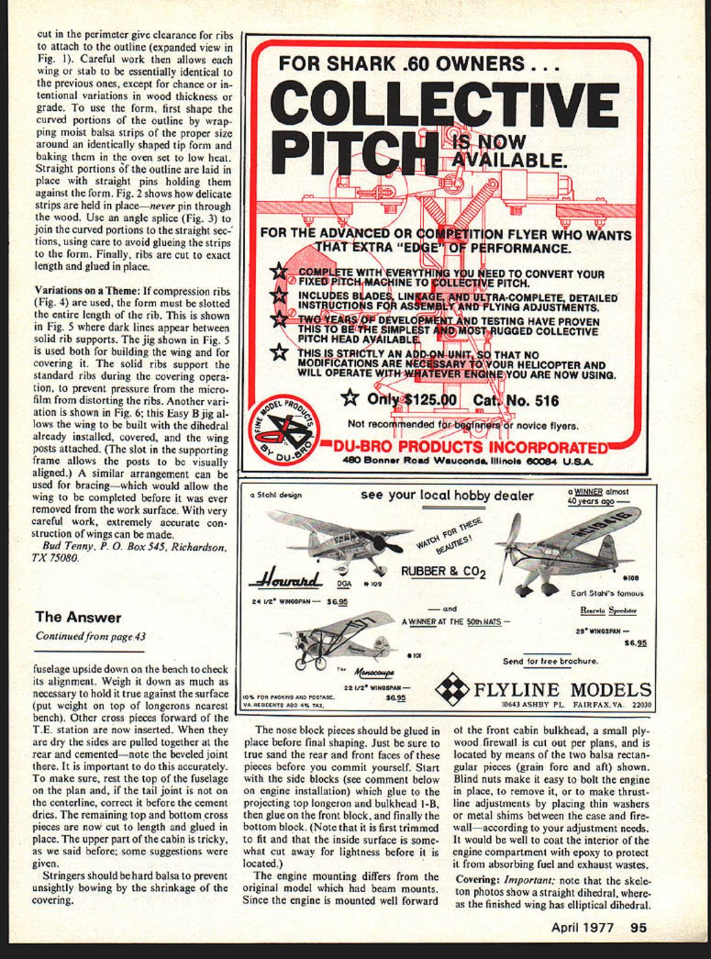
Variations on a Theme: If compression ribs (Fig. 4) are used, the form must be slotted the entire length of the rib. This is shown in Fig. 5 where dark lines appear between solid rib supports. The jig shown in Fig. 5 is used both for building the wing and for covering it. The solid ribs support the standard ribs during the covering operation, to prevent pressure from the microfilm from distorting the ribs. Another variation is shown in Fig. 6; this Easy B jig allows the wing to be built with the dihedral already installed, covered, and the wing posts attached. (The slot in the supporting frame allows the posts to be visually aligned.) A similar arrangement can be used for bracing—which would allow the wing to be completed before it was ever removed from the work surface. With very careful work, extremely accurate construction of wings can be made.
Bud Tenny, P. O. Box 545, Richardson, TX 75080.
Transcribed from original scans by AI. Minor OCR errors may remain.

