
FREE FLIGHT INDOOR
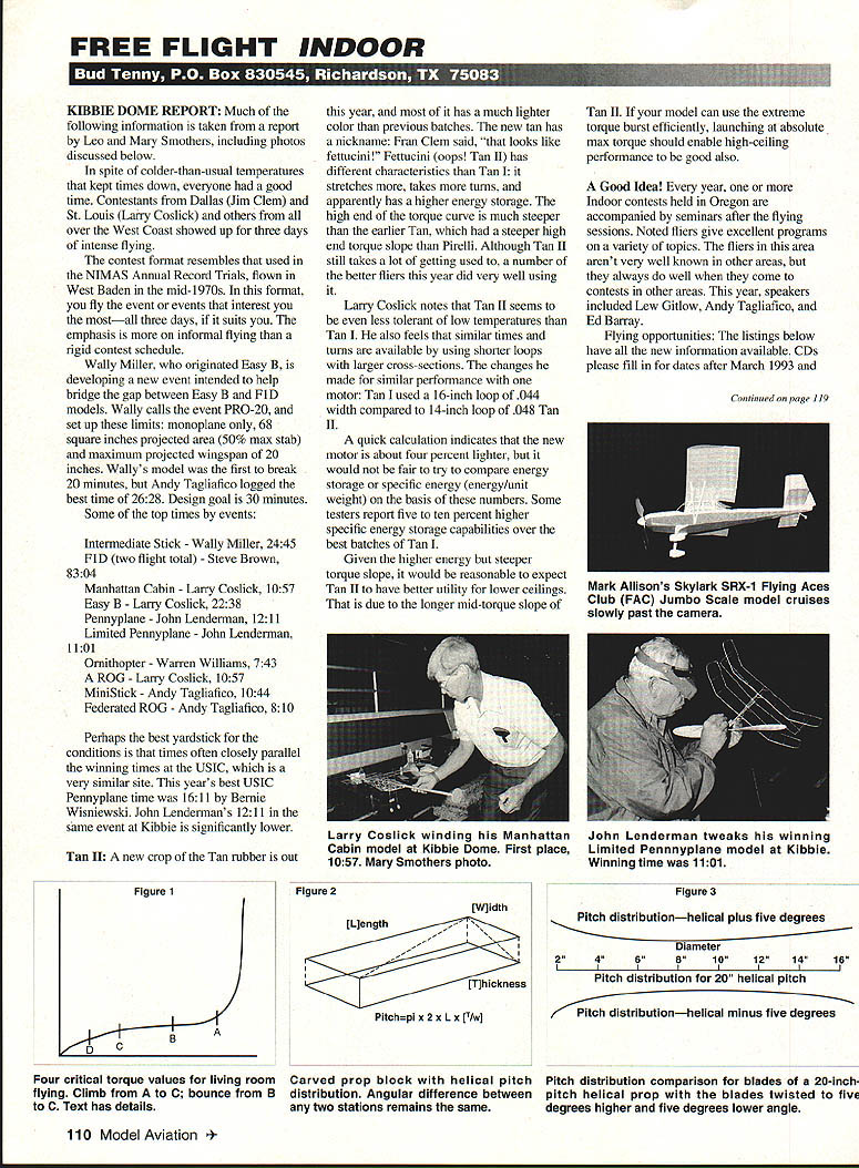
KIBBIE DOME REPORT: Much of the following information is taken from a report by Leo and Mary Smothers, including photos discussed below.
In spite of colder-than-usual temperatures that kept times down, everyone had a good time. Contestants from Dallas (Jim Clem) and St. Louis (Larry Coslick) and others from all over the West Coast showed up for three days of intense flying.
The contest format resembles that used in the NIMAS Annual Record Trials, flown at West Baden in the mid-1970s. In this format, you fly the event or events that interest you the most—all three days, if it suits you. The emphasis is more on informal flying than a rigid contest schedule.
Wally Miller, who originated Easy B, is developing a new event intended to help bridge the gap between Easy B and F1D models. Wally calls the event PRO-20, and set up these limits:
- monoplane only
- 68 square inches projected area (50% max stab)
- maximum projected wingspan: 20 inches
Wally's model was the first to break 20 minutes, but Andy Tagliafico logged the best time of 26:28. Design goal is 30 minutes.
Some of the top times by event:
- Intermediate Stick — Wally Miller, 24:45
- F1D (two flight total) — Steve Brown, 83:04
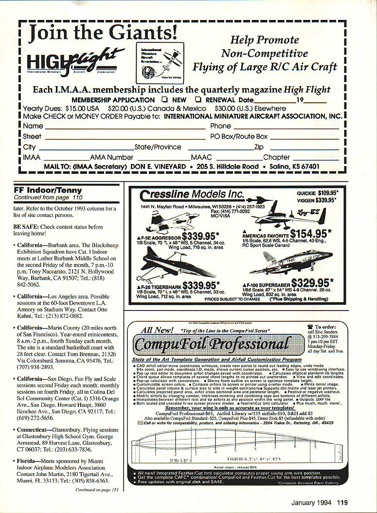
- Manhattan Cabin — Larry Coslick, 10:57
- Easy B — Larry Coslick, 22:38
- Pennyplane — John Lenderman, 12:11
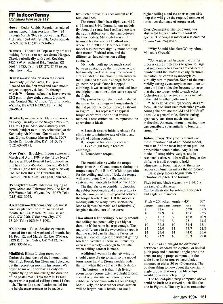
- Limited Pennyplane — John Lenderman, 11:01
- Ornithopter — Warren Williams, 7:43
- A ROG — Larry Coslick, 10:57
- MiniStick — Andy Tagliafico, 10:44
- Federated ROG — Andy Tagliafico, 8:10
Perhaps the best yardstick for the conditions is that times often closely parallel the winning times at the USIC, which is a very similar site. This year's best USIC Pennyplane time was 16:11 by Bernie Wisniewski. John Lenderman's 12:11 in the same event at Kibbie is significantly lower.
Tan II
A new crop of the Tan rubber is out this year, and most of it has a much lighter color than previous batches. The new tan has a nickname; Fran Clem said, "that looks like fettuccine." Tan II has different characteristics than Tan I: it stretches more, takes more turns, and apparently has a higher energy storage. The high end of the torque curve is much steeper than the earlier Tan, which had a steeper high-end torque slope than Pirelli. Although Tan II still takes a lot of getting used to, a number of the better fliers this year did very well using it.
Larry Coslick notes that Tan II seems to be even less tolerant of low temperatures than Tan I. He also feels that similar times and turns are available by using shorter loops with larger cross-sections. The changes he made for similar performance with one motor: Tan I used a 16-inch loop of .044 width compared to a 14-inch loop of .048 for Tan II.
A quick calculation indicates that the new motor is about four percent lighter, but it would not be fair to try to compare energy storage or specific energy (energy/unit weight) on the basis of these numbers. Some testers report five to ten percent higher specific energy storage capabilities over the best batches of Tan I.
Given the higher energy but steeper torque slope, it would be reasonable to expect Tan II to have better utility for lower ceilings. That is due to the longer mid-torque slope of Tan II. If your model can use the extreme torque burst efficiently, launching at absolute max torque should enable high-ceiling performance to be good also.
A Good Idea!
Every year, one or more indoor contests held in Oregon are accompanied by seminars after the flying sessions. Noted fliers give excellent programs on a variety of topics. The fliers in this area aren't very well known in other areas, but they always do well when they come to contests in other areas. This year, speakers included Lew Gitlow, Andy Tagliafico, and Ed Barray.
Flying opportunities
The listings below have all the new information available. Contest directors (CDs) please fill in for dates after March 1993 and later. Refer to the October 1993 column for a list of contest persons.
BE SAFE: Check contest status before leaving home!
- California — Burbank area. The Blacksheep Exhibition Squadron have Cat. I indoor meets at Luther Burbank Middle School on the second Friday of the month, 7 p.m.–10 p.m. Tony Naccarato, 2121 N. Hollywood Way, Burbank, CA 91507; Tel.: (818) 842-5062.
- California — Los Angeles area. Possible sessions at the 60-foot Downtown L.A. Armory on Stadium Way. Contact Otto Kuhni; Tel.: (213) 872-0882.
- California — Marin County (20 miles north of San Francisco). Year-round miniconts, 8 a.m.–2 p.m., fourth Sunday each month. The site is a standard basketball court with 28 feet clear. Contact Tom Brennan, 21326 Via Colombard, Sonoma, CA 95476; Tel.: (707) 938-2893.
- California — San Diego. Fun fly and scale sessions second Friday each month; monthly sessions on fourth Friday, all in Colina Del Sol Community Center (Cat. I), 5316 Orange Ave., San Diego. Howard Haupt, 3860 Ecolchee Ave., San Diego, CA 92117; Tel.: (619) 272-5656.
- Connecticut — Glastonbury. Flying sessions at Glastonbury High School Gym. George Armstead, 89 Harvest Lane, Glastonbury, CT 06037; Tel.: (203) 633-7836.
- Florida — Miami. Meets sponsored by Miami Indoor Airplane Modelers Association. Contact John Martin, 2180 Tigertail Ave., Miami, FL 33133; Tel.: (305) 858-6363.
FF Indoor/Tenny
Continued from page 119
- Iowa — Cedar Rapids. Regular scheduled unsanctioned flying sessions, Nov. ’93 through March ’94; 28-foot ceiling. Paul McIlrath, 1524 48th St. NE, Cedar Rapids, IA 52402; Tel.: (319) 393-4677.
- Kansas — Topeka. They are still looking for a site to replace Stone Hangar. Check periodically with Jack Koehler, 3425 SW Arrowhead Rd., Topeka, KS 66614-3485; Tel.: (913) 272-8439 to see what they find.
- Kansas — Wichita. Session at Friends University (28-foot site), 12–6 p.m. Planned for the first weekend each month subject to approval, Jan. ’94 through March ’94. Normal schedule: heavy events 12–2 p.m.; lightweight events 2 p.m.–6 p.m. Contact Stan Chilton, 725 E. Lincoln, Wichita, KS 67211-3302; Tel.: (316) 686-9634.
- Kentucky — Louisville. Flying sessions every Tuesday at the Sawyer Park site, 11 a.m.–1 p.m. Also, one Saturday each month (subject to military schedules) at the Kentucky Air National Guard suite 10 a.m.–2 p.m. Contact Mason Plank, 3207 Oriole Dr., Louisville, KY 40213; Tel.: (502) 634-8191.
- New York — Brooklyn. Indoor contests in March and April 1994 at the “Blue Nose” Hangar at Floyd Bennett Field, Brooklyn. Site has 150 x 450-foot floor and 45 feet to rafters (field truss beams, easy retrieval). Contact Don Ross, 38 Churchill Rd., Cresskill, NJ 07626; Tel.: (201) 568-5272.
- Pennsylvania — Philadelphia. Flying at Bryn Ath and Fairmont Park. Joe Krush, 409 Warner Rd., Wayne, PA 19087; Tel.: (215) 688-3027.
- Oklahoma — Oklahoma City. Sessions/contests planned for third weekend of month, Jan. ’94–March ’94. Jim Belson, 4933 NW 29th, Oklahoma City, OK 73129; Tel.: (405) 946-1093.
- Oklahoma — Tulsa. Sessions/contests planned for second weekend of month, Jan. 14, Feb. 12, and March 12. Roy O’Mara, 9120 E. 7th St., Tulsa, OK 74112; Tel.: (918) 835-6880.
MiniStick Hints: Living room trim
During the final days of the International MiniStick Postal, Jim Clem and I checked out the recreation room in his house. We hoped to make up for having only one regular flying session during the duration of the postal meet. This room is 19 feet square with a peaked ceiling about 14 feet high. The ceiling specification called for the height measurement to be made on a five-meter circle; this checked out at 10 feet, 1 inch.
The times? Jim’s best flight was 4:17, and I turned 3:44. Normally, our models fly about the same, but I realized too late the subtle difference in the trim between the two models. My model was still trimmed for the 26-foot Bedford site, where it did 7:00 in December. Jim’s model was trimmed slightly more nose-up than normal Bedford trim, and the difference showed most on ceiling contacts.
My model built up too much speed between contacts; by the third contact it had usually worked its way into a corner. Jim’s model did the classic stall-and-turn that tightened the circle enough for it to get near the peak. Once it stopped climbing, it was usually centered and four feet higher than mine at the same stage of the flight.
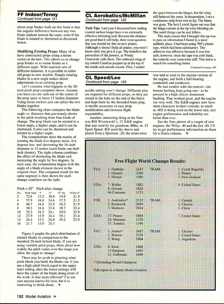
The power factor: Both models shared the same flight strategy—flying entirely on the flat part of the torque curve. This represents a typical torque curve with the critical values marked. These critical values represent the approximate ideal:
- A. Launch torque: initially chosen for climb rate to minimize rate of climb and length of ceiling contact.
- B. Torque at first ceiling contact.
- C. Level-flight torque (end of climbing).
- D. Touchdown torque.
The model climbs while the torque drops from A to C, and bounces during the torque range from B to C. With proper trim for the ceiling and lots of luck, the torque will reach point C while the model is centered well enough to land on the floor. The final factor to consider is choosing the rubber loop length and cross-section to hold the number of turns expended between the torque levels A and D. If the model is landing with too many turns, shorten the loop to tighten the model and (effectively) lengthen the first part of the curve.
How about a flat ceiling? A really smooth flat ceiling can potentially give higher duration if the room is large enough. The main difference in the two ceiling types is that the model can fly slightly faster, as long as it can ceiling-scrub without getting too far off-center. Otherwise, it must fly even more slowly—enough to hesitate when ceiling contact is made.
Additional wash in the left wingtip should cause the tip to stall, so the model turns more tightly. (Some models widen the turn with the left tip to stall.) The bottom line is that high living-room times require extensive flight testing, special adjustments, and more precise rubber selection than with higher ceilings. Most likely, the best rubber cross-section will be larger than is feasible to use in higher ceilings, and the shortest possible loop that will give the required number of turns over the range of torque used.
CyA Comments
The following was abstracted from an article in SAM 86 Speaks. The original material was credited to Woodcuts magazine.
"Why should modelers worry about molecule growth?
Some glues fail because the curing process causes molecules to grow so large that interconnecting bonds are reduced in number until the material easily fractures. In particular, certain cyanoacrylates virtually turn to powder. Some of the most rapidly curing cyanoacrylates continue to cure until the molecules become so large that they no longer weld to each other (cohesion) or to the two surfaces intended to be held together (adhesion).
The better-known cyanoacrylates are formulated to limit such molecular growth. Among the best are the 3M and Hot Stuff lines. As a general rule, slower-curing cyanoacrylates form much smaller molecules. An extra minute in curing time can contribute substantially to long-term strength."
Indoor Props
The prop is almost the most important part of an indoor model, and is half of the most important part: the prop/rubber combination. Any indoor prop of competitive weight and, in reasonable trim, will do well as long as the airframe is stiff enough to hold adjustments. From that point, the prop/rubber combination makes the difference.
Basic prop theory begins with the definition of pitch. The formula:
Pitch (of any blade element) = 3.1416 × diameter × tan(angle)
Can be illustrated by solving for pitch and angle vs. diameter.
Pitch (inches) = 3.1416 × diameter × tan(angle)
The charts highlight the difference between a standard "true-pitch" or helical-pitch prop and a constant-angle or constant-pitch prop. The constant-angle props computed in the table have flat or non-twisted blades mounted at either 30° or 45°. One obvious thing to note about the constant-angle prop is that only the blade tips would do very much pulling.
The helical-pitch prop could be built on a carved block. The key fact to remember is that the angular difference between two stations remains the same.
Modifying Existing Props
Many of us have constructed props using a tissue socket at the hub. This allows us to change prop blades or to rotate blades to a different angle. With matched sets of different diameter, it is possible to tailor old props to new models. Simply rotating blades to a new angle makes minor adjustments to an existing prop.
Let's examine what happens to the 20-inch-pitch prop computed above. Assume you have cut one inch out of the center of the prop spars to leave a 15-inch diameter. Using tissue sockets you can splice the two blades together.
The following compares the blade angle vs. diameter data previously shown to the pitch resulting from four kinds of change. The prop blade can be rotated to a lower angle, a higher angle, and it can be shortened. It also can be shortened and rotated to a higher angle.
The computations show the results of rotating the blade five degrees more, five degrees less, and shortening the 16-inch diameter to 15 inches (each blade one-half-inch shorter). The right column combines the effect of shortening the blade and increasing the angle by five degrees. In each case, the computation begins with the angle of a blade element shown in the original chart. The computed result for the same segment is then shown for each change condition on the right.
Sample results (Pitch = 20"):
- Dia. 2 — Blade Angle 72.6: -5° → 15.2; +5° → 26.6; 15" dia → 14.9; 15" dia +5° → 21.4
- Dia. 4 — Blade Angle 57.9: -5° → 16.6; +5° → 24.6; 15" dia → 17.5; 15" dia +5° → 21.5
- Dia. 6 — Blade Angle 46.7: -5° → 16.8; +5° → 23.9; 15" dia → 18.3; 15" dia +5° → 21.9
- Dia. 8 — Blade Angle 38.5: -5° → 16.6; +5° → 23.8; 15" dia → 18.7; 15" dia +5° → 22.4
- Dia.10 — Blade Angle 32.5: -5° → 16.3; +5° → 24.1; 15" dia → 19.0; 15" dia +5° → 22.9
- Dia.12 — Blade Angle 27.9: -5° → 15.9; +5° → 24.4; 15" dia → 19.1; 15" dia +5° → 23.4
- Dia.14 — Blade Angle 24.4: -5° → 15.5; +5° → 24.8; 15" dia → 19.2; 15" dia +5° → 23.9
- Dia.16 — Blade Angle 21.7: -5° → 15.0; +5° → 25.3
Figure 3 graphs the pitch distribution of rotated blades in comparison to a standard 20-inch helical blade. If you are using variable-pitch props, think about how widely the pitch varies over the range you allow the angle to change!
There may be profit in planning what pitch block you build the blades on; if you use a high-pitch block equal to the upper limit setting, then the lower settings will have the center of the blade doing more of the work. Is that more efficient? I'm not sure anyone knows for sure, but it is interesting to think about.
Transcribed from original scans by AI. Minor OCR errors may remain.

