
Free Flight: Indoor
Bud Tenny
ANOTHER NIMAS INTERNATS?
Tentative planning now underway (late February) is that the National Indoor Model Airplane Society will have another International Record Trials at Northwood Institute in West Baden, Indiana early in June. Actually, the activity will be expanded to include both the NIMAS event and the opening rounds of the Central Zone qualification trials to select the U.S. Team for the 1978 Indoor World Championship. Final decision time on this activity will come at a time not compatible with the next issue of this column, so anyone interested can get information on the NIMAS Internats by sending a self-addressed, stamped envelope to Box 545, Richardson TX 75080.
Jigs Insure Accuracy:
Motorsticks and tail booms are rolled on special forms, while flying surfaces use special templates instead of plans. How then does the whole model get properly aligned? Well, some of them are propped up on toolboxes or stacks of books, but the easy way is to use a four-piece all-purpose set of alignment jigs. Such a set is described below; it has served me well for about ten years. Since it is portable, this set of jigs has travelled hundreds of miles and has helped me repair and re-align models at virtually every major contest I have attended.
Fuselage Cradle:
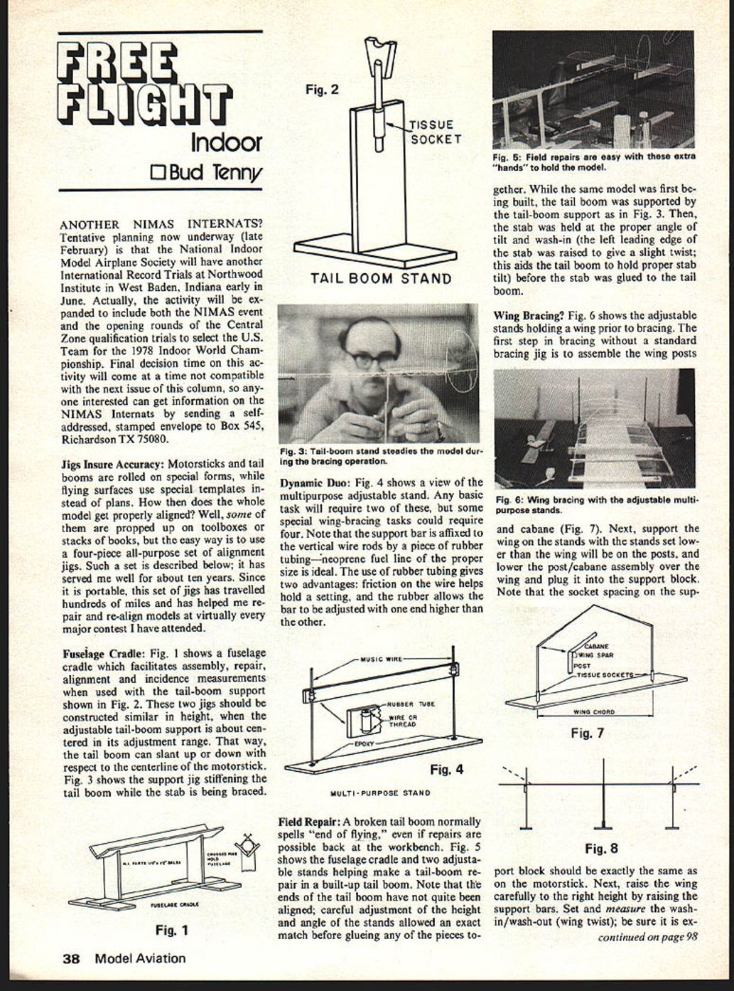
Fig. 1 shows a fuselage cradle which facilitates assembly, repair, alignment and incidence measurements when used with the tail-boom support shown in Fig. 2. These two jigs should be constructed similar in height, when the adjustable tail-boom support is about centered in its adjustment range. That way, the tail boom can slant up or down with respect to the centerline of the motorstick. Fig. 3 shows the support jig stiffening the tail boom while the stab is being braced.
Dynamic Duo:
Fig. 4 shows a view of the multipurpose adjustable stand. Any basic task will require two of these, but some special wing-bracing tasks could require four. Note that the support bar is affixed to the vertical wire rods by a piece of rubber tubing—neoprene fuel line of the proper size is ideal. The use of rubber tubing gives two advantages: friction on the wire helps hold a setting, and the rubber allows the bar to be adjusted with one end higher than the other.
Field Repair:
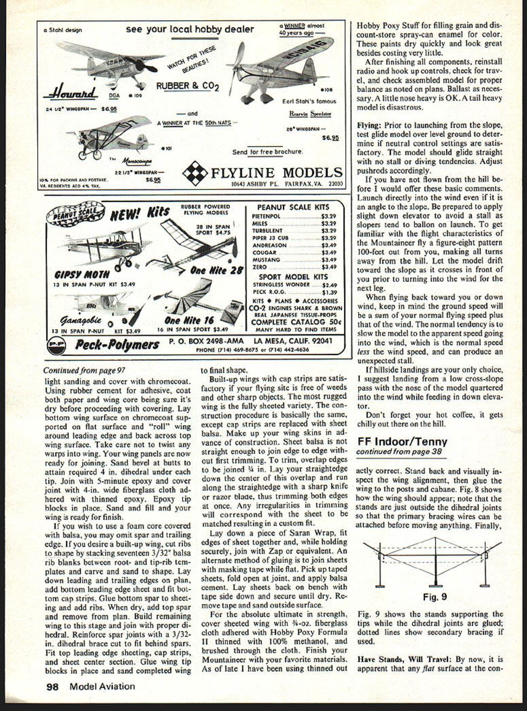
A broken tail boom normally spells "end of flying," even if repairs are possible back at the workbench. Fig. 5 shows the fuselage cradle and two adjustable stands helping make a tail-boom repair in a built-up tail boom. Note that the ends of the tail boom have not quite been aligned; careful adjustment of the height and angle of the stands allowed an exact match before gluing any of the pieces together. While the same model was first being built, the tail boom was supported by the tail-boom support as in Fig. 3. Then, the stab was held at the proper angle of tilt and wash-in (the left leading edge of the stab was raised to give a slight twist; this aids the tail boom to hold proper stab tilt) before the stab was glued to the tail boom.
Wing Bracing?
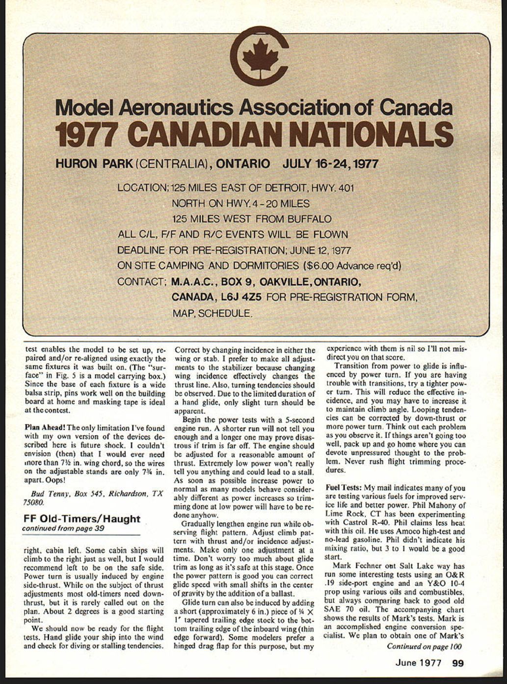
Fig. 6 shows the adjustable stands holding a wing prior to bracing. The first step in bracing without a standard bracing jig is to assemble the wing posts and cabane (Fig. 7). Next, support the wing on the stands with the stands set lower than the wing will be on the posts, and lower the post/cabane assembly over the wing and plug it into the support block. Note that the socket spacing on the support block should be exactly the same as on the motorstick. Next, raise the wing carefully to the right height by raising the support bars. Set and measure the wash-in/wash-out (wing twist); be sure it is exact. When everything is exactly correct, stand back and visually inspect the wing alignment, then glue the wing to the posts and cabane. Fig. 8 shows how the wing should appear; note that the stands are just outside the dihedral joints so that the primary bracing wires can be attached before moving anything. Finally,
Have Stands, Will Travel: By now, it is apparent that any flat surface at the con- Test enables the model to be set up, repaired and/or re-aligned using exactly the same fixtures it was built on. (The "surface" in Fig. 5 is a model carrying box.) Since the base of each fixture is a wide balsa strip, pins work well on the building board at home and masking tape is ideal at the contest.
Plan Ahead!
The only limitation I've found with my own version of the devices described here is future shock. I couldn't envision (then) that I would ever need more than 7½ in. wing chord, so the wires on the adjustable stands are only 7¼ in. apart. Oops!
Bud Tenny, Box 545, Richardson, TX 75080.
Correct by changing incidence in either the wing or stab. I prefer to make all adjustments to the stabilizer because changing wing incidence effectively changes the thrust line. Also, turning tendencies should be observed. Due to the limited duration of a hand glide, only a slight turn should be apparent.
Begin the power tests with a 5-second engine run. A shorter run will not tell you enough and a longer one may prove disastrous if trim is far off. The engine should be adjusted for a reasonable amount of thrust. Extremely low power won't really tell you anything and could lead to a stall. As soon as possible increase power to normal as many models behave considerably different as power increases so trimming done at low power will have to be redone anyhow.
Gradually lengthen engine run while observing flight pattern. Adjust climb pattern with thrust and/or incidence adjustments. Make only one adjustment at a time. Don't worry too much about glide trim as long as it's safe at this stage. Once the power pattern is good you can correct glide speed with small shifts in the center of gravity by the addition of a ballast.
Glide turn can also be induced by adding a short (approximately 6 in.) piece of 1/4 x 1 tapered trailing edge stock to the bottom trailing edge of the inboard wing (thin edge forward). Some modelers prefer a hinged drag flap for this purpose, but my experience with them is nil so I'll not misdirect you on that score.
Transition from power to glide is influenced by power to turn. If you are having trouble with transitions, try a tighter power turn. This will reduce the effective incidence, and you may have to increase it to maintain climb angle. Looping tendencies can be corrected by down-thrust or more power turn. Think out each problem as you observe it. If things aren't going too well, pack up and go home where you can devote unpressured thought to the problem. Never rush flight trimming procedures.
Fuel Tests:
My mail indicates many of you are testing various fuels for improved service life and better power. Phil Mahony of Lime Rock, CT has been experimenting with Castrol R-40. Phil claims less heat with this oil. He uses Amoco high-test and no-lead gasoline. Phil didn't indicate his mixing ratio, but 3 to 1 would be a good start.
Mark Fechner out Salt Lake way has run some interesting tests using an O&R .19 side-port engine and an Y&O-10-4 prop using various oils and combustibles, but always comparing back to good old SAE 70 oil. The accompanying chart shows the results of Mark's tests. Mark is an accomplished engine conversion specialist. We plan to obtain one of Mark's
Transcribed from original scans by AI. Minor OCR errors may remain.

