
FREE FLIGHT INDOOR
Bud Tenny, Box 830545, Richardson, TX 75083
A-6 Follow-up
There has been a lot of activity on the Internet regarding the International E-Mail A-6 Indoor Contest, announced in the November 1997 column. Special note: if you request the A-6 plan mentioned there, please send your requests to R. Schroeder, 4111 West 98 St., Overland Park, KS 66207. Any other address will only delay receipt of the plan.
Access the web site http://n1emm.com/a6/ap6/theap6.html for a step-by-step text-and-picture guide for building an A-6. Del Ogren has done an excellent job with this; if you are not familiar with what is possible on the Internet, you will be surprised.
Addendum to A-6 Rules
This was left out of the rules given in the column:
- The A-6 propeller blades are flat pieces cut from 1/32" sheet. They cannot be cambered or twisted.
- The total diameter cannot exceed six inches.
This makes an easy prop for beginners to make. Despite the crude arrangement, A-6 props appear to be reasonably efficient.
Indoor RC Electric Duration — Follow-up
Bob Wilder has done it again — two ways.
- He has flown an Electric FF model (no radio) powered by two 50 mAh cells for more than 10 minutes at the Bedford (TX) site. Note that there currently is no AMA class for this model, but it follows the guidelines developed by Ken Johnson and others flying in the Tustin hangars (Santa Ana) preliminary to submitting a rules proposal for the class.
- He has drastically redesigned his RC Duration model. The airplane (Indoor RC Electric, AMA event #627) was flown for 4:19 in the Bedford Boys Ranch Cat 1 site. Although Bob has become a fairly good RC pilot, the model on that record flight was flown by Ernie Harwood. The model weighed 114 grams, with a wing area of 248 square inches. The motor was a German coreless driving a carbon-fiber propeller through a handmade 8:1 ratio gearbox. The power was four 350-mAh cells.
The Indoor Group now has more than 130 members. Join us by sending your request to Bud Tenny at rten@nstarnet. Note: this is a change in address. By the time this issue arrives, the previous address may be phased out. Current members, please update your address lists.
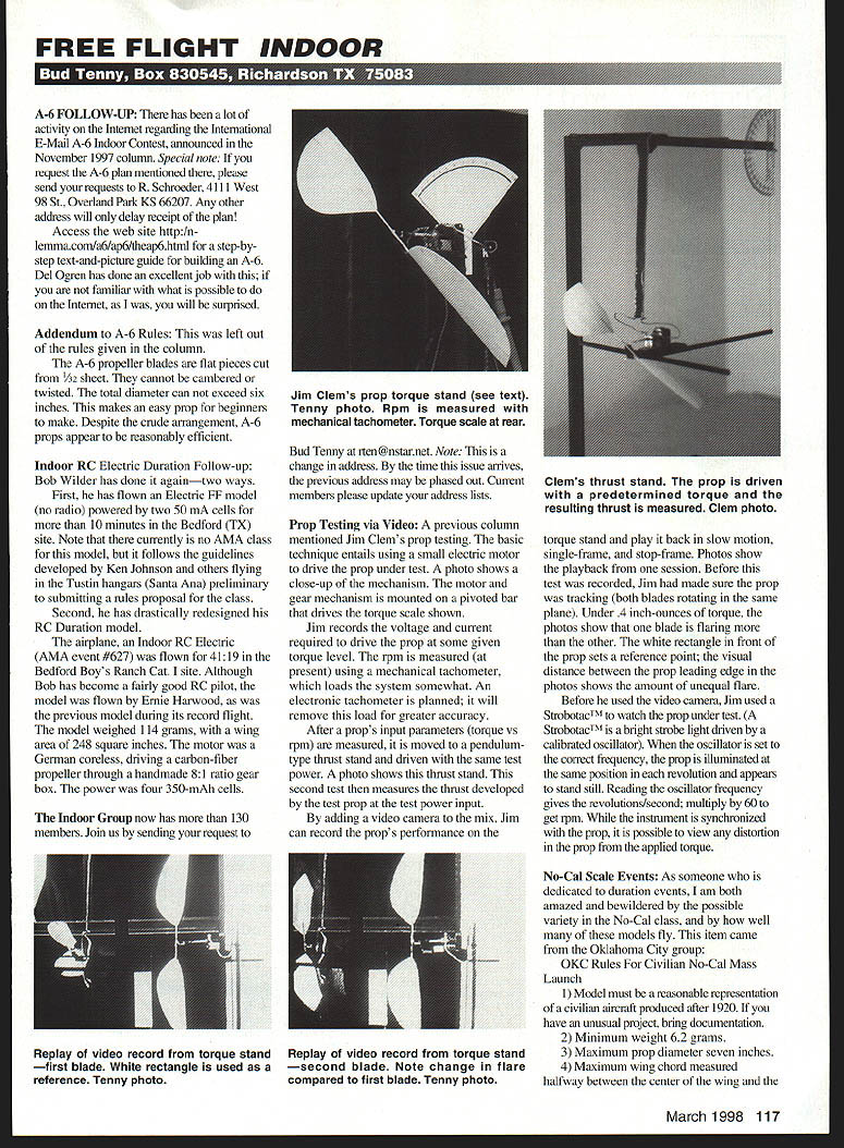
Prop Testing via Video
A previous column mentioned Jim Clem's prop testing. The basic technique entails using a small electric motor to drive the prop under test. The motor and gear mechanism is mounted on a pivoted bar that drives the torque scale; Jim records the voltage and current required to drive the prop at a given torque level. The rpm is measured (at present) using a mechanical tachometer, which loads the system somewhat. An electronic tachometer is planned; it will remove this load for greater accuracy.
After a prop's input parameters (torque vs rpm) are measured, it is moved to a pendulum-type thrust stand and driven with the same test power. This second test measures the thrust developed by the test prop at the same power input.
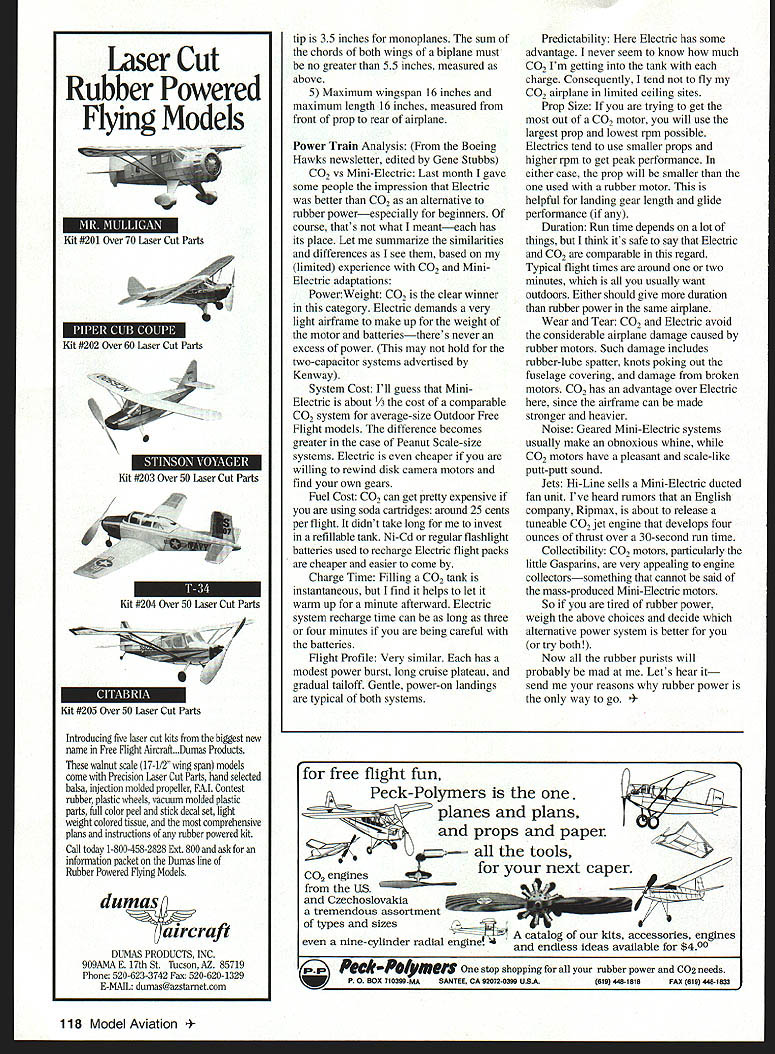
By adding a video camera to the mix, Jim can record the prop's performance on the torque stand and play it back in slow motion, single-frame, and stop-frame. Before recording, Jim ensures the prop is tracking (both blades rotating in the same plane). Under 4 in-oz of torque, the video shows one blade flaring more than the other. A white rectangle placed in front of the prop sets a reference point; the visual distance between the prop leading edge and the front of the rectangle shows the amount of unequal flare.
Before he used a video camera, Jim used a Strobotac™ to watch the prop under test. A Strobotac™ is a bright strobe light driven by a calibrated oscillator. When the oscillator is set to the correct frequency, the prop is illuminated at the same position in each revolution and appears to stand still. Reading the oscillator frequency gives revolutions per second; multiply by 60 to get rpm. While synchronized with the prop, it is possible to view any distortion in the prop from the applied torque.
No-Cal Scale Events: OKC Rules for Civilian No-Cal Mass Launch
As someone dedicated to duration events, I am amazed and bewildered by the variety in the No-Cal class and by how well many of these models fly. This item came from the Oklahoma City group:
- Model must be a reasonable representation of a civilian aircraft produced after 1920. If you have an unusual project, bring documentation.
- Minimum weight 62 grams.
- Maximum propeller diameter seven inches.
- Maximum wing chord measured halfway between the center of the wing and the tip is 3.5 inches for monoplanes. The sum of the chords of both wings of a biplane must be no greater than 5.5 inches, measured as above.
- Maximum wingspan 16 inches and maximum length 16 inches, measured from front of prop to rear of airplane.
Power Train Analysis (From the Boeing Hawks newsletter, edited by Gene Stubbs)
CO2 vs Mini-Electric: Last month I gave some people the impression that Electric was better than CO2 as an alternative to rubber power—especially for beginners. Of course, that's not what I meant—each has its place. Here are the similarities and differences based on limited experience with CO2 and Mini-Electric adaptations:
- Power/Weight: CO2 is the clear winner. Electric demands a very light airframe to make up for the weight of the motor and batteries—there's never an excess of power. (This may not hold for the two-capacitor systems advertised by Kenway.)
- System Cost: Mini-Electric is about half the cost of a comparable CO2 system for average-size outdoor free flight models. The difference is greater for Peanut Scale-size systems. Electric is even cheaper if you rewind disk camera motors and find your own gears.
- Fuel Cost: CO2 can get expensive if you use soda cartridges (about 25 cents per flight). A refillable tank reduces cost. Ni-Cd or regular flashlight batteries used to recharge Electric flight packs are cheaper and easier to obtain.
- Charge Time: Filling a CO2 tank is instantaneous (allow a minute to warm up). Electric recharge can take three to four minutes if you are careful with the batteries.
- Flight Profile: Very similar—modest power burst, long cruise plateau, and gradual tailoff. Gentle, power-on landings are typical of both systems.
- Predictability: Electric has some advantage. CO2 fills can vary, so CO2 models are less predictable in limited-ceiling sites.
- Prop Size: To maximize CO2 motor output, use the largest prop and lowest rpm possible. Electrics tend to use smaller props and higher rpm. In either case, props are smaller than those used with rubber motors.
- Duration: Comparable. Typical flight times are around one to two minutes outdoors—more than rubber in the same airplane.
- Wear and Tear: CO2 and Electric avoid damage caused by rubber motors (lube spatter, knots poking out fuselage covering, broken motors). CO2 allows a somewhat stronger and heavier airframe.
- Noise: Geared Mini-Electric systems often produce an obnoxious whine; CO2 motors have a pleasant, scale-like putt-putt sound.
- Jets: Hi-Line sells a Mini-Electric ducted fan unit. Rumors indicate an English company, Ripmax, may release a tunable CO2 jet.
- Collectibility: CO2 motors, particularly the little Gasparin, are appealing to engine collectors—something not usually said of mass-produced Mini-Electric motors.
If you are tired of rubber power, weigh the above choices and decide which alternative power system is better for you (or try both!). Send your reasons if you think rubber power is the only way to go.
Transcribed from original scans by AI. Minor OCR errors may remain.

