
FREE FLIGHT INDOOR
Bud Tenny, Box 830545, Richardson TX 75083
BEDFORD REPRISE
In the last column I noted that the gymnasium at the Bedford Boys Ranch in Bedford, Texas, was no longer used for indoor flying because of the blowers running continuously.
Actually, heavy scale models and electric-powered models are still flown there during weekly sessions.
SCIENCE OLYMPIAD HELP
The Cleveland Clowns, a very active model club in the Cleveland, Ohio, area, are conducting active training for entrants and adult mentors. The club is also staging what sounds like practice competition.
Contact Dr. Vernon Hacker (Hack) via email at vhacker@pol.net or call (216) 486-4990 to get in on the fun.
GUERRILLA FLIERS IN PENN STATION (NEW YORK CITY)
Don Ross, a columnist for Flying Models magazine, recently reported that some people had been flying indoor scale models in New York's Penn Station. The basic idea was to show indoor models to a large number of people. Subsequent discussions, especially with regard to safety, led Don to discourage the idea.
He feels that we might get some really good publicity if the effort could be restricted to Limited Pennyplane and lighter models. Without strict control of the activity, those who would try heavier or faster models could get us all into trouble.
Certainly, no club should miss opportunities to fly demonstrations using safe models, such as pennyplanes. The best possible outcome would be that the club gains a member or two, regular access to a site it proved during the demonstration(s), and sometimes even a short newspaper article or 30 seconds on television.
I am an advisor member of a personal robot club; sometimes television coverage comes out really well and sometimes it doesn't. We have friends at the Dallas Morning News, so no problem!
WHERE ARE THE JUNIORS?
Darryl Stevens (Darryl.Stevens@PSS.Boeing.com) sent me an email after noting that four European countries fielded full junior teams, while the U.S. had only Nick Leonard Jr. entered in junior competition. More email in the thread follows.
Darryl: This is almost embarrassing in the way that we have only one junior listed, and quite possibly Nick may be the only one who is flying F1D in the U.S. I can't think of any others.
Bud: Good to hear from you! What do you suggest?
Darryl: Unless you have a father who is involved with modeling, you just can't drive yourself to Idaho to fly. Hobby shops do not support indoor because there isn't much money in it, and flying sites are hard to come by. I've two RC fields within 10 miles of my home here in Seattle. On weekends there are many more spectators than fliers. The following week some of the spectators have new almost-ready-to-fly models to fly. I even have trouble myself keeping motivated knowing that Moscow may be my only real indoor flying opportunity for the year. No real suggestions—it's sad, but already indoor is becoming "indoor RC" for most.
RUBBER TEST REPRISE
The swing-arm rubber test rig (photos and commentary in the previous column) is sufficiently operational to allow preliminary testing. The shakedown test runs used a 10-inch loop made from 0.093-inch-wide Tan II of unknown pedigree (most likely 5-94). Test runs continued until I became familiar with the rig and had some level of confidence in the measurement equipment.
The next step is to learn to make standardized test motors so direct comparison between different batches of Tan II can be made.
BUILDING TEST MOTORS — MEASURING TECHNIQUES
I make all test motors 0.6 grams in weight; this will help me develop skills I can use in F1D competition. Before flying a new motor, I use a test windup to prove the knot is sound and the motor is free of major flaws.
However, 0.6-gram motors are different. Since the motor weight in F1D 5.5 competition can't exceed 0.6 grams, changing the model's power must be done by changing the rubber cross-section. Therefore, each motor will be a different length, to use the maximum allowable amount of rubber.
CROSS-SECTION AND LENGTH MEASUREMENT
I measure a test sample of rubber using a yardstick clamped in a vise so it stands vertical. I hold the end of the strip even with the top of the yardstick, with the rubber strip hanging by its own weight.
If the sample is to be longer than three feet, I use sharp tweezers to grip the rubber exactly at the end of the yardstick, and I move the tweezers to the top of the yardstick. For a five-foot-long sample, I cut the strip at the 24-inch mark.
I use one-inch machinist's micrometer calipers for cross-section measurement. Many fliers use spring-loaded calipers to measure rubber strip; regardless of how much the spring tension has been relieved, the rubber will be compressed to some degree.
I avoid the compression by carefully closing the micrometer while sliding the rubber strip back and forth. I take the reading at the calipers setting where the rubber barely begins to drag between the jaws, avoiding compression of the rubber.
That may seem overly perfectionist, but any undefined compression of the rubber affects the accuracy of a cross-section calculation. I don't mean to imply that spring calipers shouldn't be used at the flying field—nearly accurate measurements made with the same calipers are quite satisfactory for choosing the next motor.
PREPARATION OF TEST MOTORS
Some preliminary tests indicated that useful 0.6-gram motors would have a strip width between 0.065 inch and 0.052 inch (nominal).
All test motors will be evaluated on the basis of weight per unit length. The rubber strip of nominal 0.065-inch width is actually logged as 0.0404 grams per inch. A 0.6-gram motor made from this strip will be a loop approximately 7.5 inches long.
The other end of the useful range (my guess) is 0.031 grams per inch (nominal 0.052-inch width); a 0.6-gram motor from this strip would make a loop approximately 9.7 inches long.
TEST-MOTOR IDENTIFICATION
Each glassine envelope (available at stamp-collector supply stores) will be marked with the following:
- A unique name
- Initial strip size (grams per inch; e.g., 0.0404 g/in)
- Weight of the motor
- Initial loop length
- Length of loop after test-wind (before rest)
The loop will settle to a rested length after several test runs. The length will be checked immediately after each test; this will be compared to the rest length.
RUN-DOWN STANDS
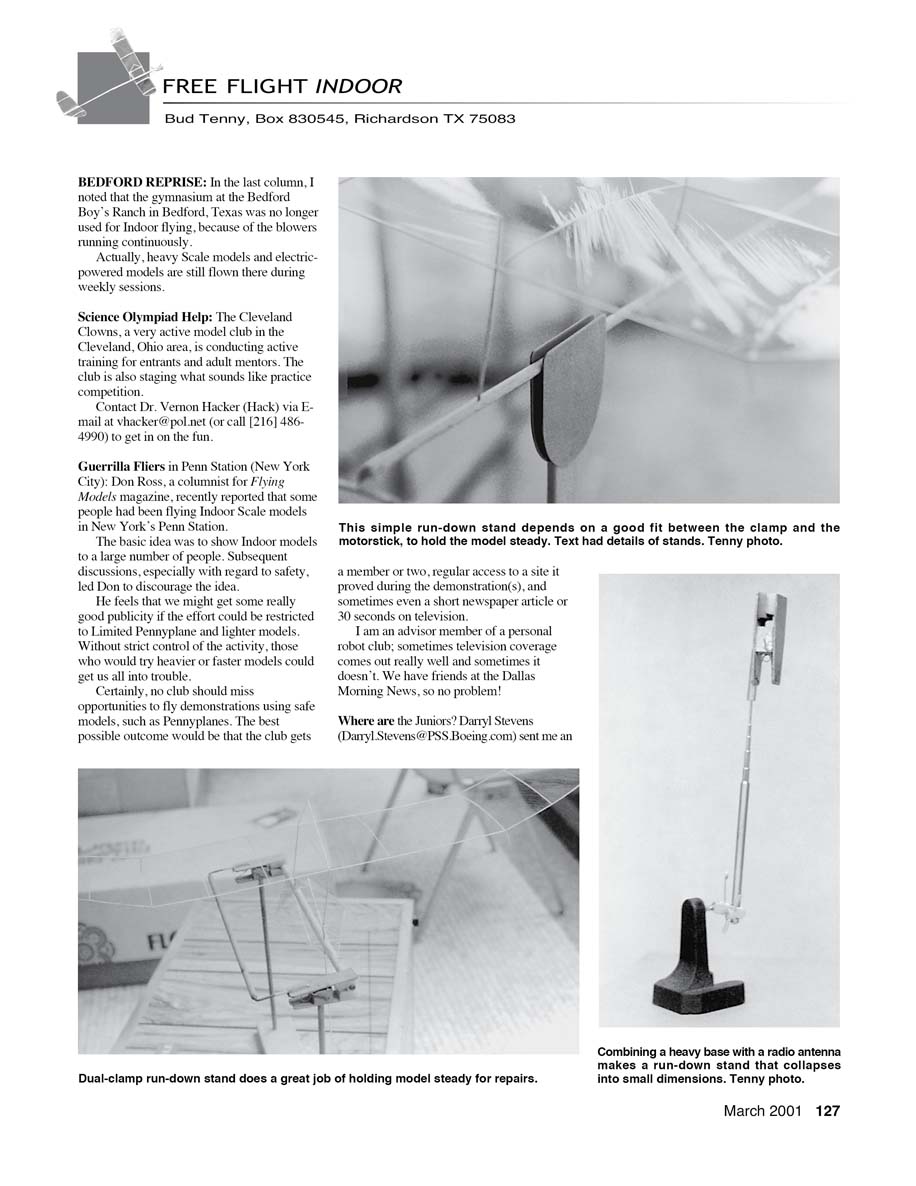
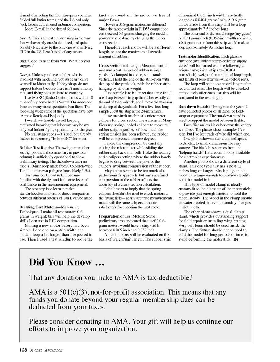
Over the years I have collected photos of all kinds of field-support equipment. The run-down stand is used to support the model between flights. Each flier makes his or her own; the variety is endless. The photos show examples I've seen, but I've lost track of who did which one.
One photo shows a stand that collapses or folds to small dimensions for easy storage. The black base comes from the "helping hands" fixture commonly available for electronics experimenters.
Another photo shows a different style of stand. This one typically has a post 12 inches long or longer, which plugs into a wood base large enough to provide stability with the model in it. This type of model clamp is ideally custom-fit to the diameter of the motorstick to provide just enough friction to hold the model steady. The wood in the clamp should be waterproofed to avoid humidity changes in slot width.
A third photo shows a dual-clamp stand, which provides outstanding support for field repair or installing wing bracing. Very soft foam should be used inside the clamps. The fixture should not be used to hold the model for long periods of time, to avoid deforming the motorstick.
—MA
Transcribed from original scans by AI. Minor OCR errors may remain.

