
FREE FLIGHT INDOOR
Bud Tenny, Box 830545, Richardson TX 75083
GOOD-BYE, FRIEND
Two days before his 77th birthday, Jim Clem passed away after more than two weeks in the hospital. Initially he had an intestinal blockage that had to be bypassed. He was always in fragile health, suffering from arthritis and scoliosis most of his life. Before he met his beloved Fran, he lost a lung to pneumonia at a time when medical science had few effective treatments.
It was long after that when Jim and Fran met at Southern Methodist University. They courted in his Cessna and Cadillac, and produced two sons: Jimmy and Mike. There are a total of six grandchildren.
I was privileged to ride in that Cessna when Jim and I went to Longview, Texas, to enter an annual AAA contest. Jim’s Speed models and my Stunt and Combat models rode in the backseat, and the toolboxes were stowed in the luggage area.
From that time on, Jim and I went to contests across the country. This continued after we both started flying indoor; we either drove to the US Indoor Championships (USIC) or flew on commercial airlines to the Kibbie Dome. We flew at the Bedford Boys Ranch until site management stopped allowing the air conditioners to be turned off. The loss of Bedford removed the last local site where we could test-fly safely to prepare for USIC. Until the YMCA raised the family membership rates, we flew models in the Y gymnasium. Jim turned to extensively test-flying MiniStick models in the 14-foot ceiling recreation room at his house. I gave up on trying to do any meaningful model-airplane development and became an advisor at the personal robotics club, where my years of instrumentation and test experience could be put to good use.
Meanwhile, Jim continued to experiment with propellers and model configurations. When the Federation ROG was conceived on the East Coast, he began to experiment.
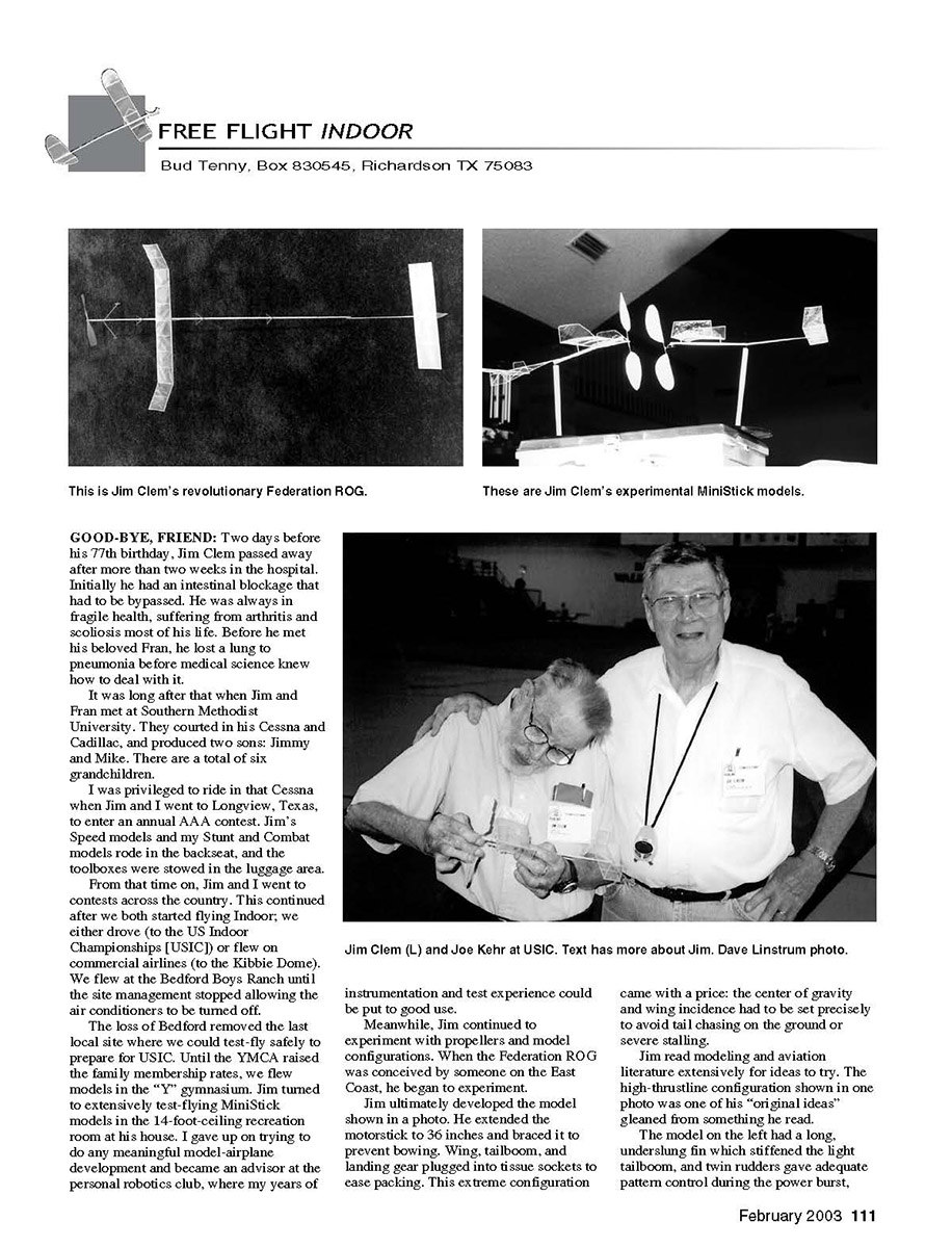
Jim ultimately developed the model shown in a photo. He extended the motorstick to 36 inches and braced it to prevent bowing. Wing, tailboom, and landing gear plugged into tissue sockets to ease packing. This extreme configuration came with a price: the center of gravity and wing incidence had to be set precisely to avoid tail chasing on the ground or severe stalling.
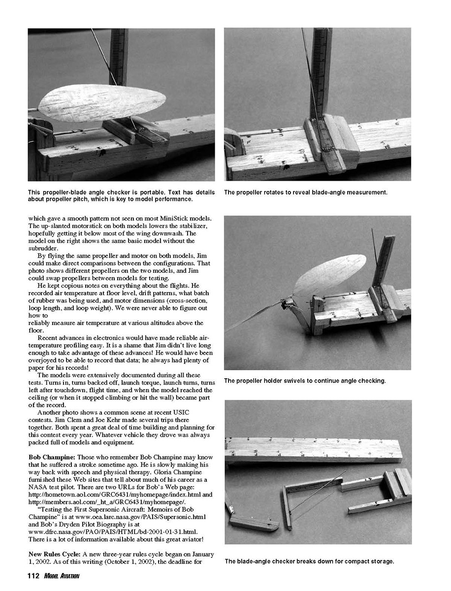
Jim read modeling and aviation literature extensively for ideas to try. The high-thrustline configuration shown in one photo was one of his "original ideas" gleaned from something he read.
The model on the left had a long, underslung fin which stiffened the light tailboom, and twin rudders gave adequate pattern control during the power burst, producing a smooth pattern not seen on most MiniStick models.
The up-slanted motorstick on both models lowers the stabilizer, hopefully getting it below most of the wing downwash. The model on the right shows the same basic model without the subrudder. By flying the same propeller and motor on both models, Jim could make direct comparisons between the configurations. He kept copious notes on everything about the flights. He recorded air temperature at floor level, drift patterns, what batch of rubber was being used, and motor dimensions (cross-section, loop length, and loop weight). We were never able to figure out how to reliably measure air temperature at various altitudes above the floor. Recent advances in electronics would have made reliable air-temperature profiling easy. It is a shame that Jim didn’t live long enough to take advantage of these advances—he would have been overjoyed to record that data; he always had plenty of paper for his records. The models were extensively documented during all these tests.
Turns in, turns backed off, launch torque, launch turns, turns left after touchdown, flight time, and when the model reached the ceiling (or when it stopped climbing or hit the wall) became part of the record.
Another photo shows a common scene at recent USIC contests. Jim Clem and Joe Kehr made several trips there together. Both spent a great deal of time building and planning for this contest every year. Whatever vehicle they drove was always packed full of models and equipment.
Bob Champine
Those who remember Bob Champine may know that he suffered a stroke some time ago. He is slowly making his way back with speech and physical therapy. Gloria Champine furnished these web sites that tell much of his career as a NASA test pilot:
"Testing the First Supersonic Aircraft: Memoirs of Bob Champine" is at:
Bob's Dryden Pilot Biography is at:
There is a lot of information available about this great aviator.
New Rules Cycle
A new three-year rules cycle began on January 1, 2002.
Propeller Pitch
The pitch of a propeller is key to model performance. Two factors are important: actual pitch and equal pitch between the two blades. If the blades have unequal pitch, the propeller will wobble. This reduces thrust and upsets model trim. Before trying to get a new model into the best trim, make sure the propeller is running properly. After that, it will be easier to adjust the model so that it flies to its maximum potential.
When you build the propeller, take special pains to build in the pitch you think you need. Test-flying may suggest a lower pitch is needed, or the model may seem to stall easily. If you have a smaller propeller or can borrow one, check the stall recovery. If it performs better, the new propeller may be suffering from tip stall; that is, the propeller itself could be stalling.
So before building a new, lower-pitch propeller, you may want to twist the propeller spar to reduce the pitch of each blade and fiddle with it until it runs true. In the case of suspected tip stall, twist the tips to a lower angle and try again. You want to know what pitch the propeller is now, but how?
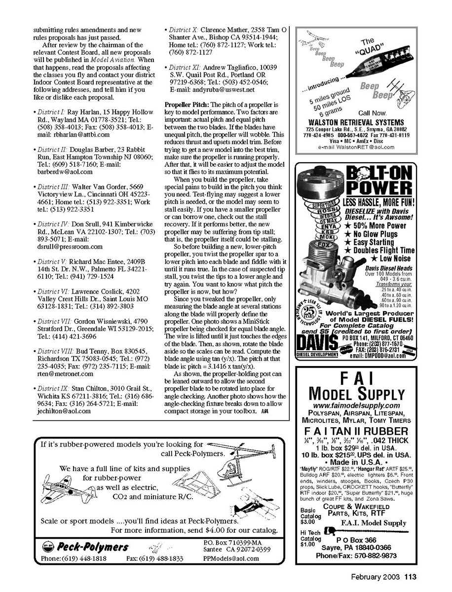
Since you tweaked the propeller, only measuring the blade angle at several stations along the blade will properly define the propeller. One photo shows a MiniStick propeller being checked for equal blade angle. The wire is lifted until it just touches the edges of the blade. Then rotate the blade aside so the scale can be read. Compute the blade angle using tan(y/x). The pitch at that blade is:
pitch = 3.1416 × tan(y/x)
As shown, the propeller-holding post can be leaned outward to allow the second propeller blade to be rotated into place for angle checking. Another photo shows how the angle-checking fixture breaks down to allow compact storage in your toolbox.
Transcribed from original scans by AI. Minor OCR errors may remain.

