
Free Flight: Indoor
Bud Tenny
How's Your Models?
With the coming of indoor season, now is the time to check out those models. This year, take time to really preflight the models—assemble them ready for flight and examine everything. Remember that last contest where the model hung up just as the meet ended? You cracked the wing spar getting it down, and the prop may be damaged too. It was late, the end of the season, so you just packed the models for the long trip home. Don't wait until test flying at the meet next week and risk buckling the wing or finding that the prop now wobbles!
What About Warps?
Indoor models sometimes seem to be warp generators, and a contest field is not the time to make the proper corrections. Four kinds of warps are prevalent: covering-induced warps, repair warps, packing warps, and warps caused by a change in humidity. Of these, packing warps are the easiest to prevent, and often are easy to remove.
In general, packing warps are caused by lack of care when packing the models in their box. Unnoticed, a wingtip may be left pressing against the side of the box or against another part. If the fixtures that hold model parts in place are loose, the parts can shift and contact the box or another model. Continued light pressure causes the structure to "set" in this new configuration. Correct the fixture to hold better, or move its mounting so there is less chance of mis-mounting the model next time. As for the warp, it can often be worked out by gently “massaging” the structure back into alignment. If the covering has tightened to accommodate the warp, repair the covering before tackling the structure.
Fixing Warps
Repair warps are caused by inadequate or hasty field repairs, or possibly by pulling glue. Perhaps the model was flown before the glue was completely dry and the joint shifted, or the alignment was not right during the repair. Either way, the joint must be soaked loose and re-glued.
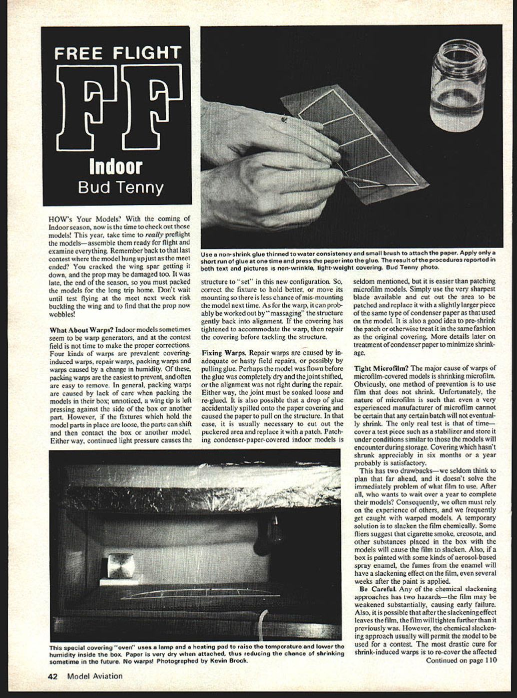
It is also possible that a drop of glue accidentally spilled onto paper covering and caused the paper to pull on the structure. In that case, it is usually necessary to cut out the puckered area and replace it with a patch. Patching condenser-paper-covered indoor models is seldom mentioned, but it is easier than patching microfilm-covered models. Use the very sharpest blade available, cut out the area to be patched, and replace it with a slightly larger piece of the same type of condenser paper used on the model. Pre-shrink the patch or otherwise treat it in the same fashion as the original covering. (See Condenser Paper Techniques below for more on pre-shrinking and treatment.)
Tight Microfilm?
The major cause of warps on microfilm-covered models is shrinking microfilm. Obviously, one method of prevention is to use film that does not shrink. Unfortunately, even an experienced manufacturer cannot be certain any given batch will not eventually shrink. The only real test is time—cover a test piece such as a stabilizer and store it under conditions similar to those encountered during storage. Coverings that haven't shrunk appreciably in six months to a year are probably satisfactory.
This has two drawbacks—we seldom think to plan that far ahead, and it doesn't solve the immediate problem of what film to use. After all, who wants to wait over a year to complete a model? Consequently, we often must rely on the experience of others and frequently get caught with warped models. A temporary solution is to slacken the film chemically. Some fliers suggest that cigarette smoke, creosote, and other substances placed in the box with the models will cause the film to slacken. Also, if a box is painted with certain aerosol-based spray enamels, the fumes from the enamel will have a slackening effect on the film, even several weeks after the paint is applied.
Be Careful
Any chemical slackening approach has two hazards—the film may be weakened substantially, causing early failure; and after the slackening effect ends, the film may tighten further than it previously was. However, chemical slackening usually will permit the model to be used for a contest.
The most drastic cure for shrink-induced warps is to re-cover the whole surface, which is often the best long-term solution. Alternatively, span-wise shrinking stress can sometimes be relieved by making a slit between ribs and parallel to them, then patching the slit while the warp is pulled flat. This takes practice; the major problem is making the cut without severely tearing the film. Similar tactics are used to relieve small areas that pull localized warps—careful planning is needed to minimize the area involved. Success depends on skill, practice, luck, and having a very tear-resistant film. If you succeed in patching, you gain practice and save time and effort; otherwise, re-covering the surface is the remaining option.
Condenser Paper Techniques
Condenser paper can be difficult to work with. Many folks recommend pre-shrinking the paper so future shrinkage is minor. Another idea is to wad the paper—roll it into a tiny ball and then spread it out—to create a network of tiny wrinkles that reduce the effect of shrinkage.
Condenser paper is not porous; it is intended as an electrical insulator and is manufactured with very few pinholes. It is densely constructed, making it virtually impossible to attach by doping through the paper. The paper also expands considerably as it absorbs water and shrinks greatly as moisture is removed. The key to a successful method is to attach it when it is very dry—drier than it will ever be on the model. Then changes in moisture content can only cause it to grow less tight as the model moves between climates.
How to dry it out: bake condenser paper before covering during winter in cold locales, or otherwise over-dry it. Be careful covering the model in highly humid air immediately afterward, as the paper may expand again.
A recommended setup is a special covering “hangar”: a heavy cardboard carton with flaps glued together and one side cut out, leaving a narrow lip all around. Inside place a heating pad, a cardboard work surface, a 75-watt lamp, and a hygrometer/thermometer. A plastic curtain covers the box front to retain heat and dry air. Make sure the box itself has had time to dry thoroughly before use.
How to use it: place the part to be covered inside the box with a piece of condenser paper cut to approximate size, leaving a half-inch margin all around. Leave everything inside until warm and dry, then cover the surface inside the box. Keep the curtain down and reach under it to work. After the covering is attached, remove the part and trim the excess paper with a new razor blade for best results.
Choice of adhesive changes from builder to builder. One effective adhesive is microfilm solution. If you don't have that, thin Duco Household Cement, Sig LiteCote (a non-tautening butyrate dope), or some heavily plasticized dope can be used. Thin the adhesive with a slowly evaporating thinner to almost the consistency of water, and apply with a fine-tip brush.
Apply a very sparing amount of adhesive to the paper immediately under the wood and only a short length at a time. Press the wood into the glue and hold until it sticks. Begin by tacking the paper to the middle of a center rib or wing tip, then tack the centers of the tips. Work toward the tips a little at a time, alternating between the leading and trailing edges so the paper is fastened evenly. Fasten the paper to dihedral ribs and add the dihedral after covering is complete.
Happy flying!
Flying Sessions / Contests
- Miami, FL — Season began with a meet set for Dec. 9, 1979. For 1980 schedule contact John Martin, 3227 Darwin St., Miami, FL 33133.
- New York City — Contact Ron Williams for the 1980 schedule at the Low Liberty Rotunda, Columbia University: 1364 Lexington Ave., New York, NY 10022.
- Minneapolis, MN area — Contests on Jan. 27 and Mar. 23, 1980. Contact John O'Leary, 11425 Kell Circle, Bloomington, MN 55437.
- Oklahoma City, OK — Meets in January at the National Guard Armory: Jan. 20, Feb. 17 and Mar. 16, 1980. Contact Al Bissonette, 6528 SE 15th, Midwest City, OK 73110.
Bud Tenny, P.O. Box 545, Richardson, TX 75080
MANITO
Tom Hutchinson
Editor's Note
We are pleased and proud to publish this excellent free-flight article. Its story began in 1972–73 when these pictures and plans were prepared, and a special challenge led to its publication. After reading the introduction you'll agree that Tom made all his points. What he goes on to say about construction and flight adjustments belongs in any pro free-flighter's scrapbook.
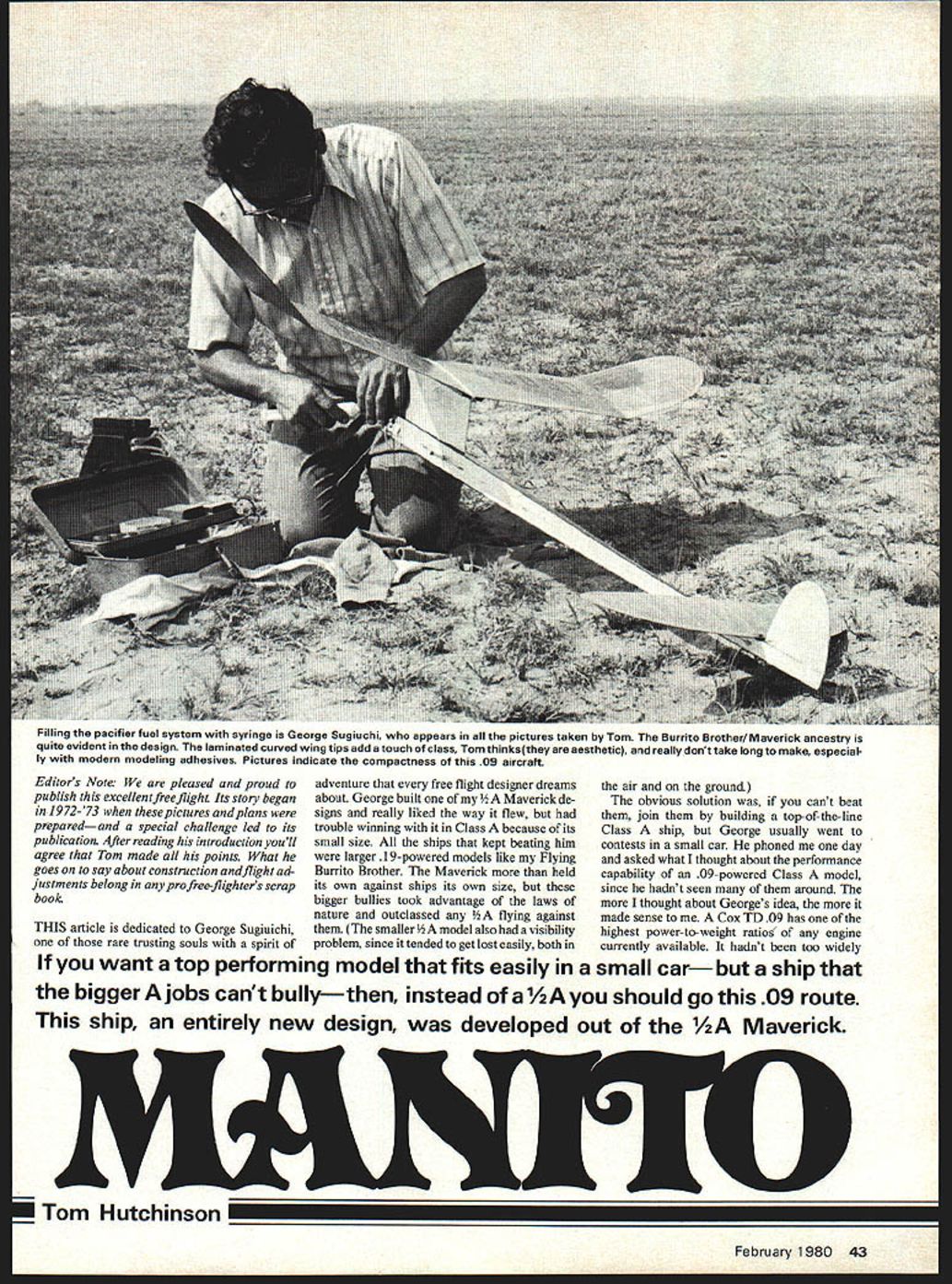
This article is dedicated to George Sugiuchi, one of those rare trusting souls with a spirit of adventure that every free-flight designer dreams about. George built one of my 1/2A Maverick designs and really liked the way it flew, but had trouble winning with it in Class A because of its small size. All the ships that kept beating him were larger .19-powered models like my Flying Burrito Brother. The Maverick more than held its own against ships its own size, but these bigger bullies took advantage of the laws of nature and outclassed any 1/2A flying against them. The smaller 1/2A model also had a visibility problem, since it tended to get lost easily, both in the air and on the ground.
The obvious solution was, if you can't beat them, join them by building a top-of-the-line Class A ship. George usually went to contests in a small car and asked me one day what I thought about the performance capability of an .09-powered Class A model, since he hadn't seen many of them around. The more I thought about George's idea, the more it made sense. A Cox TD .09 has one of the highest power-to-weight ratios of any engine then available. It hadn't been too widely used because you can't readily switch engines and fly two classes with the same model. But a model built strictly for Class A competition with this engine would be more potent than a 1/2A because of its larger size and higher power. You'd also have a model that didn't take up very much more room in the car than a typical 1/2A.
If you want a top-performing model that fits easily in a small car—but a ship that the bigger A jobs can't bully—then, instead of a 1/2A you should go this .09 route. This ship, an entirely new design, was developed out of the 1/2A Maverick.
Design and Development
Since George liked the way the Maverick flew, we decided that the new design would be based on its proportions as much as possible. I made some quick calculations and phoned back the dimensions to George. The next day, he showed up with a complete set of working drawings for my approval. Within two weeks he had the first prototype completed and ready for test flights.
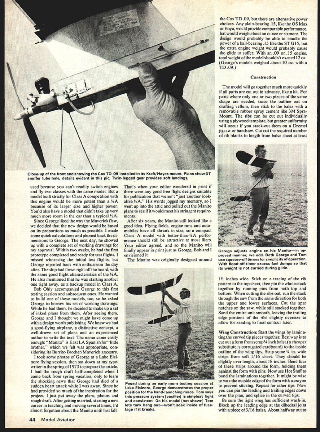
I missed witnessing the initial test flights, but George reported back with enthusiasm the day after. The ship had flown right off the board, with the same good flight characteristics of the 1/2A. He also mentioned that he was starting another one right away, as a backup model in Class A.
Bob Ohly accompanied George to the first testing sessions and subsequent ones. He wanted to build one of these models, too, so he asked George to borrow his working drawings. While he had them, he made a set of inked plans from them. After seeing them, George and I thought we might have come up with a good-flying airplane, a distinctive concept, a well-drawn set of plans, and an experienced author to write the text. The name came easily: "Manito" is East L.A. Spanish for "little brother," which we felt was appropriate given its Burrito Brother/Maverick ancestry.
I took some photos of George at a Lake Elsinore flying session, then sat down in the spring of 1973 to prepare the article. I had the rough draft half-completed when I returned from spring vacation to learn the shocking news that George had died of a heart attack while I was away. Since he had provided so much of the inspiration for the project, I put away the plans, photos, and rough draft. After getting married, starting a new career in teaching, and moving several times, I'd almost forgotten about the Manito until last fall.
Your editor's comment in print wondering if there were any good free-flight designs suitable for publication that weren't "just another look-alike 1/2A" jogged my memory, so I pulled the Manito plans from the attic to see if it would meet his requirements. After six years, the Manito still looked like a good idea. Flying fields, engine runs, and automobiles have all shrunk in size, so a compact Class A model with better-than-1/2A performance should still be attractive to most fliers. Your editor agreed, and so the Manito will finally appear in print just as George, Bob, and I envisioned it.
The Manito was originally designed around the Cox TD .09, but there are alternative power choices. Any plain-bearing .15, like certain OS Max or Enya engines, would provide comparable performance but weigh about an ounce more. The design would probably handle the power of a ball-bearing .15 like the ST G15, but the extra engine weight would likely cause the glide to suffer. With an .09 or .15 engine, total weight of the model shouldn't exceed 12 oz. (George's models weighed about 10 oz. with a TD .09.)
Construction
The model will go together much more quickly if all parts are cut out in advance, like a kit. For parts where only one or two pieces of the same shape are needed, trace the outline on drafting vellum, then stick it to the balsa with removable rubber spray cement such as 3M Spray-Mount.
Ribs can be cut individually using a plywood template, but greater uniformity occurs if you stack-cut them on a Dremel jigsaw or bandsaw. Cut the required number of rib blanks to length from balsa sheet at least 1½ inches wide. Stick a tracing of the rib pattern to the top sheet, then pin the whole stack together by running pins from both top and bottom. When cutting the ribs, run the stack through the saw from the same direction for both the upper and lower surfaces. Cut the spar notches on the saw while still stacked together. Sand the entire unit smooth, leaving the trailing edge portions of the ribs slightly oversize to allow for sanding to final contour later.
Wing Construction
Start the wings by laminating the curved tip pieces together. The best way is to cut out a form from scrap 1/4-inch balsa (a cheaper substitute is corrugated cardboard) to the inside outline of the wingtips. Strip some 1/4-inch wide strips from soft 1/16-inch sheet. They should be full length, about 18 inches. Bend four of these strips around the form, holding them against the form with pins. Use Hot Stuff (cyanoacrylate) to bond the laminations together. It might be wise to wax the outside edge of the form with a crayon to prevent sticking. Repeat for the other tip.
Pin the leading and trailing edges down over the plan and splice in the curved tips. Be sure the right wing has sufficient wash-in. Block up the leading edge at the dihedral joint with a piece of 3/16-inch balsa. About halfway out to the tip, glue in the dihedral brace and continue assembly as shown on the plans.
(Continue construction and finishing per the detailed plans and photos provided with the Manito plans.)
Transcribed from original scans by AI. Minor OCR errors may remain.

