
Free Flight: Indoor
Bud Tenny
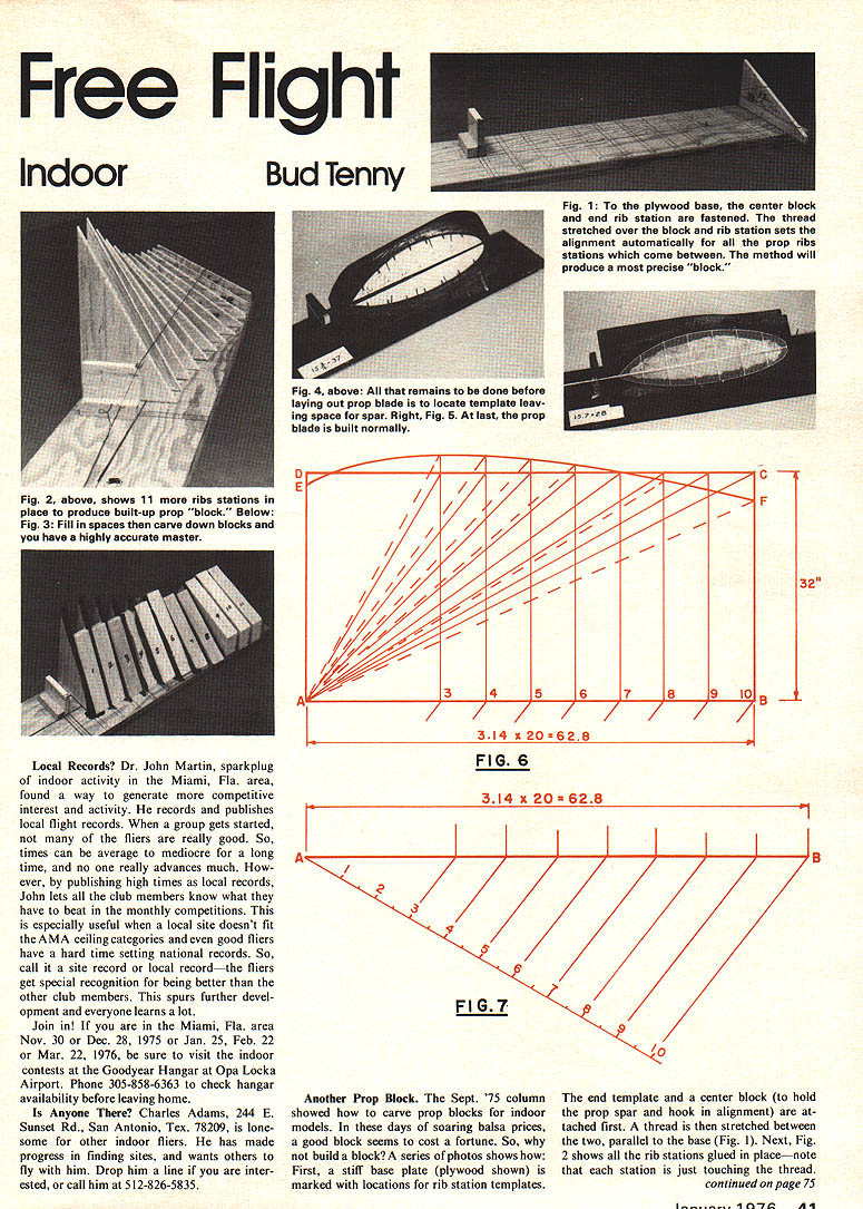
Another Prop Block. The Sept. '75 column showed how to carve prop blocks for indoor models. In these days of soaring balsa prices, a good block seems to cost a fortune. So, why not build a block? A series of photos shows how: First, a stiff base plate (plywood shown) is marked with locations for rib station templates. The end template and a center block (to hold the prop spar and hook in alignment) are attached first. A thread is then stretched between the two, parallel to the base (Fig. 1). Next, Fig. 2 shows all the rib stations glued in place—note that each station is just touching the thread. At this point, a propeller can be built on the fixture by pinning the outline directly to the rib station templates. Careful handling of the jig and the prop outline is necessary, since it is largely unsupported. This type of prop block is invaluable for experimenting with pitch distribution since individual rib stations can be replaced to change blade angle at any part of the blade.
Finish it up? If you already know what pitch your models need, it may be desirable to finish out the surface to resemble a carved block. So, Fig. 3 shows balsa blocks inserted between rib stations. Fig. 4 shows the surface carved to shape and a prop blade template in place. Fig. 5 shows a completed prop blade on the form.
Which is better? This correspondent prefers prop fixtures of the type shown in Fig. 2 because it is easy to change pitch distribution by changing rib station angles. However, the fixture is relatively fragile and requires careful storage. The filled-in block requires less care in handling during prop construction and is much easier to use for prop repair. Both types are cheaper and better for experimentation—non-helical prop blocks are almost impossible to carve.
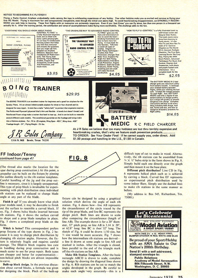
Built-up block design. In the previous discussion about carved blocks, a formula was given for designing the block. Pitch of the built-up fixture can be designed by using a graphical solution which derives the angle of each rib station. Fig. 6 shows how—line AB represents the circumference of the circle traced by the tip of the prop blade, and line BC represents the design pitch. Both lines are drawn to scale after computing the circumference. The example shown is for a 20" diameter, 32" pitch prop; line AB is 3.14 x 20 = 62.8" long, and line BC is 32" long. The sketch of Fig. 6 could be drawn 1/10 size, but 1/5 size would be more accurate.
Fig. 7 shows how the intermediate rib stations are derived—now the radius is drawn at some angle to line AB and marked in inches. After the triangle is closed, lines parallel to line BC are drawn from the points where the ribs meet line AB.
Make Rib Station Templates. After the basic rectangle ABCD is drawn to scale, complete the design by drawing the diagonal lines shown in Fig. 6. Rib stations can be cut to match the angles developed in the graph. Be careful to make each angle very accurately—this is a difficult type of cut to make in wood. Alternatively, the rib stations can be assembled from 1/8" x 1/2" balsa strip in the form shown in Fig. 8. Simply build each one directly over the graph and mount it on the base plate.
Different pitch distributions? Line CD in Fig. 6 represents helical pitch such as is achieved by carving a block. Curved line EF represents an experimental pitch distribution used by some indoor fliers. Simply use the dashed lines to make rib stations in the same manner as before.
(My address is: Box 545, Richardson, Tex. 75080.)
Transcribed from original scans by AI. Minor OCR errors may remain.

