
Free Flight: Indoor
Bud Tenny
Repair Fixtures Revisited
A couple of columns ago I showed a photo of my field repair fixtures in use during a repair session. Some of you wanted more information on these gadgets, so here goes.
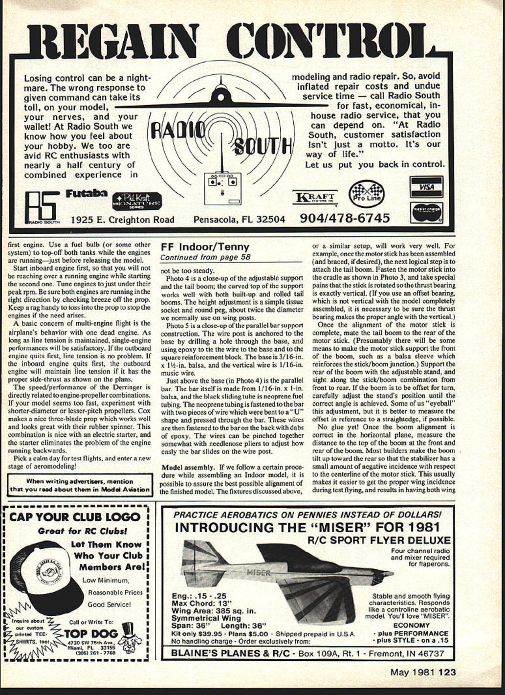
Photo 1 shows the basic setup as it might be used on the bench during model assembly. On the left is the fuselage cradle; two straight pins cross the motor stick to hold it in place with gentle pressure. At the rear is a simple adjustable-elevation support, commonly used to support the bare tail boom during initial assembly. The rear support has been taped to the table for stability.
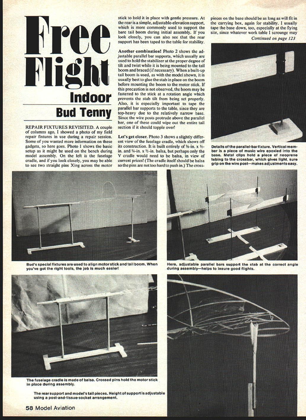
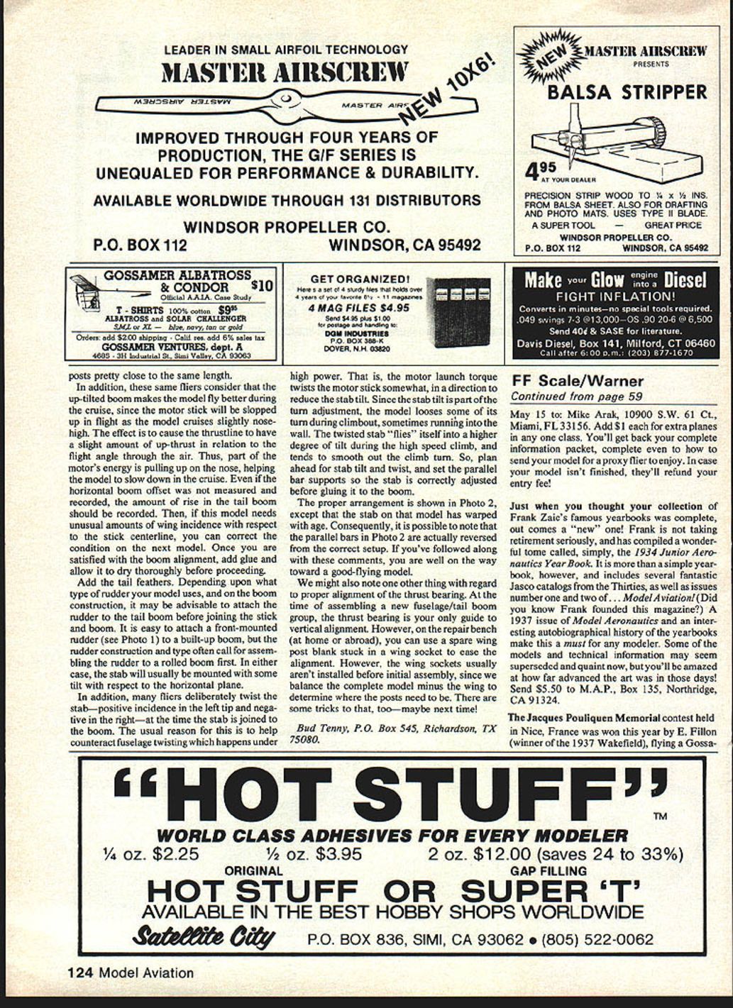
Photo 2 shows the adjustable parallel-bar supports, which are usually used to hold the stabilizer at the proper degree of tilt and twist while it is being mounted to the tail boom and braced (if necessary). When a built-up tail boom is used, as with the model shown, it is usually best to glue the stab in place on the boom before mounting the boom to the motor stick. If this precaution is not observed, the boom may be fastened to the stick at a rotation angle that prevents the stab tilt from being set properly. It is especially important to tape the parallel-bar supports to the table, since they are top-heavy due to the relatively narrow base. Because the wire posts protrude above the parallel bar, one of these could wipe out the entire tail section if it should topple over.
Photo 3 shows a slightly different view of the fuselage cradle and its construction. It is built entirely of 3/8 in. x 3/8 in. x 1/8 in. balsa, although perhaps only the V cradle needs to be balsa in view of current prices. The cradle itself should be balsa so the pins are not too hard to push in. The crosspieces on the base should be as long as will fit in the carrying box for stability. I usually tape the base down, especially at the flying site, since whatever work table I scrounge may not be too steady.
Photo 4 is a close-up of the adjustable support and the tail boom; the curved top of the support works well with both built-up and rolled tail booms. The height adjustment is a simple tissue-socket and round peg about twice the diameter we normally use on wing posts.
Photo 5 is a close-up of the parallel-bar support construction. The wire post is anchored to the base by drilling a hole through the base and using epoxy to tie the wire to the base and to the square reinforcement block. The base is 3/16 in. x 1-1/2 in. balsa, and the vertical wire is 1/16 in. music wire.
The parallel bar itself is made from 1/16 in. x 1 in. balsa, and the black sliding tube is neoprene fuel tubing. The neoprene tubing is fastened to the bar with two pieces of wire bent to a U shape and pressed through the bar; these wires are then fastened to the back of the bar with dabs of epoxy. The wires can be pinched together somewhat with needle-nose pliers to adjust how easily the bar slides on the wire post.
Model Assembly
If you follow a certain procedure while assembling an indoor model, you can assure the best possible alignment of the finished model. The fixtures discussed above, or a similar setup, work very well.
- Assemble the motor stick (and brace it, if desired). Fasten the motor stick into the cradle (as shown in Photo 3) and take special pains that the stick is rotated so the thrust bearing is exactly vertical. If you use an offset bearing (which is not vertical with the model completely assembled), be sure the thrust bearing makes the proper angle with the vertical.
- Mate the tail boom to the rear of the motor stick. Support the rear of the boom with the adjustable stand and sight along the stick/boom combination from front to rear. If the boom is to be offset for trim, carefully adjust the stand's position until the correct angle is achieved. Some fliers "eyeball" this adjustment, but it is better to measure the offset with reference to a straightedge, if possible.
- In the horizontal plane, once boom alignment is correct, measure the height to the top of the boom at the front and rear. Most builders make the boom tilt up toward the rear so the stabilizer has a small amount of negative incidence with respect to the centerline of the motor stick. This usually makes it easier to get proper wing incidence during test flying and results in having both wing panels at about the same incidence. Also check the wing saddle alignment on the boom and align it to the motor stick centerline.
- No glue yet: When satisfied with all alignments, tack-glue the boom to the motor stick using a small amount of adhesive at the forward and rear joints. Recheck alignment after tack-gluing, then finish gluing. Allow glue to dry thoroughly before proceeding.
- After the boom is glued, assemble the rest of the airframe and fit the wing carefully in the saddle. It is common to let the wing sit in the saddle and hold it there with a small clip while gluing so that you can check the incidence easily.
When the model is complete, balance it fore and aft as the plans recommend and check throughout for proper alignment. If any trim changes are necessary, make them by shifting the wing slightly fore or aft, or by adding small amounts of weight to the nose or tail. Ailerons or differential thrust are seldom used on indoor models; trimming is normally done with wing tilt (wash-in/wash-out), stabilizer incidence, or small tip-weight adjustments.
Add the Tail Feathers
Depending on the type of rudder and the boom construction, it may be advisable to attach the rudder to the tail boom before joining the stick and boom. It is easy to attach a front-mounted rudder to a built-up boom, but rudder construction often calls for assembling the rudder to a rolled boom first. In either case, the stabilizer is usually mounted with some tilt relative to the horizontal plane.
Many fliers deliberately twist the stab—positive incidence in the left tip and negative in the right—when joining the stab to the boom. The usual reason is to help counteract fuselage twisting under high power: motor launch torque can twist the motor stick and reduce the stab tilt. Since stab tilt is part of the trim adjustment, the model can lose some of its turning climb and sometimes run into the wall. The twisted stab tends to fly into a higher degree of tilt during the high-speed climb and smooth out the climb turn. Plan ahead for stab tilt and twist, and set the parallel-bar supports so the stab is correctly adjusted before gluing it to the boom.
The proper arrangement is shown in Photo 2, except that the stab on that model has warped with age; consequently, the parallel bars in Photo 2 are actually reversed from the correct setup.
Thrust-Line, Trim and Test Flights
Many fliers consider that the up-tilted boom makes the model fly better during cruise, since the motor stick will be sloped up in flight as the model cruises slightly nose-high. The effect is to give the thrust line a slight amount of up-thrust relative to the flight angle through the air. Thus, part of the motor's energy pulls up on the nose, helping the model slow down in the cruise. Record the amount of rise in the tail boom so you can reproduce or correct the setup on the next model if unusual wing incidence is required.
When making test flights, pick a calm day and launch gently.
- If the model dives: reduce the thrust or add a bit of up-elevator.
- If the model climbs and stalls: add nose weight or increase thrust slightly.
Keep detailed notes of changes made so you can repeat successful setups. With patience and careful alignment, your indoor free-flight models will reward you with smooth, predictable flights.
We might also note one other thing with regard to proper alignment of the thrust bearing. At initial assembly the thrust bearing is your only guide to vertical alignment. On the repair bench, you can use a spare wing post blank stuck in a wing socket to ease alignment. Wing sockets usually aren't installed before initial assembly, since we balance the complete model minus the wing to determine where the posts need to be. There are some tricks to that—maybe next time!
Bud Tenny P.O. Box 545 Richardson, TX 75080
Transcribed from original scans by AI. Minor OCR errors may remain.

