
Free Flight: INOOR
Bud Tenny
Bostonian
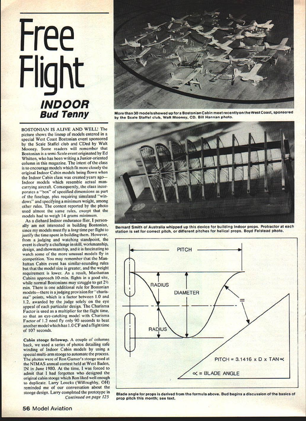
BOSTONIAN IS ALIVE AND WELL! The picture shows the lineup of models entered in a special West Coast Bostonian event sponsored by the Scale Staffel club and CD'd by Walt Mooney. Some readers will remember that Bostonian is a semi-scale event originated by Ed Whitten, who has been writing a junior-oriented column in this magazine. The intent of the class is to encourage models which fit more closely the original indoor cabin models being flown when the Indoor Cabin class was created years ago—indoor models which resemble actual man-carrying aircraft. Consequently, the class incorporates a "box" of specified dimensions as part of the fuselage, requires simulated "windows," and specifies a minimum weight, among other rules. The contest reported by the photo used almost the same rules, except that the models had to weigh a minimum of 14 grams.
As a diehard indoor endurance flier, I personally am not interested in building Bostonians, since my models must fly a long time per flight to justify the time spent in building them. However, from a judging and watching standpoint, the event is clearly a challenge in skill, workmanship, design, and showmanship, and it is fascinating to watch some of the more unusual models fly in competition. You may remember that the Manhattan Cabin event has similar-sounding rules but that the model size is greater and the weight requirement is lower. As a result, Manhattan Cabins approach 10-minute flights in a good site, while normal Bostonians may struggle to get 2½ minutes. There is one additional rule for Bostonian models—there is a judging provision for "charisma" points, which is a factor between 1.0 and 1.2, awarded by the judge solely on the eye appeal of each particular design. The Charisma Factor is used as a multiplier for the flight time, so that an eye-catching model with a Charisma Factor of 1.2 need fly only 90 seconds to beat another model which has 1.0 CF and a flight time of 107 seconds.
Cabin stooge followup
A couple of columns back, we used a series of photos detailing safe winding of indoor cabin models by using a special multi-arm stooge to automate the process. The photos were of Ron Ganser's stooge used at the NIMAS annual contest held at West Baden, IN in June 1980. At the time, I was forced to admit that I had forgotten who designed the original cabin stooge which Ron liked well enough to duplicate. Larry Loucka (Willoughby, OH) reminded me of our conversation about the stooge design. Larry completed the prototype in time for the 1980 Midwest Indoor Championships in Chicago, and later used it at the 1980 Nats to send off the Cabin flights which won Indoor Cabin. At the 1980 NIMAS meet, Tony Sutter (Corpus Christi, TX) also had a similar stooge, apparently designed at about the same time.
FAI rules followup
Since the last word on Erv Rodemsky's proposal to drop FAI class F1D model span to 60 cm, along with a limit on rubber weight and some other restrictions, Erv's planned 60 cm contest was held in the Santa Ana hangar on December 27, 1981. Of course, with all the extremely competent FAI fliers in California, one of them won, right? Wrong! Eighteen-year-old Darryl Stevens, son of HLG whiz Curt Stevens, won it all and then went on to set a new Senior Indoor HLG record the same day! The flight times came out this way (high single flight used for scoring):
- Darryl Stevens, 2548
- Erv Rodemsky, 2506
- Cezar Banks, 2227
- Warren Williams, 2006
- Clarence Mather, 2005
- Andy Faykun, 1700
It should be noted that one change to the rules as originally proposed was in effect for this contest: the rubber weight had been increased to a maximum of 3/4 gram instead of the original 1/2-gram proposal. Erv noted that one basic goal of the rules proposal has been demonstrated—no one except Faykun hit the ceiling, and there were no long periods of time spent near the ceiling as has been typical of F1D events in recent years. Now that the basic proposal has been out and discussed by indoor fliers all over the world, the inevitable rash of counter-proposals has come about. Many of these are being aired in Model Aviation and other publications, and Erv has been working with a number of people in trying to deal with the problem. The latest consensus among U.S. fliers (also shared by some fliers from other countries) is that no change should be made to F1D rules for the present, but that a new class could be established to explore in depth some of the concepts developed during the present discussion. To that end, Erv has brought forth the following proposal which was hammered out with the aid of Dan Domina and John Triolo.
50cm Intermediate Indoor Duration Model (proposal)
- Projected wingspan: 50 cm (19.69 in.) maximum.
- Length (excluding propeller): 50 cm maximum.
- Model weight: at least one gram without motor.
- Wing area: 650 sq. cm. (100.78 sq. in.) maximum.
- Stab span: 30 cm (11.81 in.) maximum.
- Stab area: 325 sq. cm. (50.39 sq. in.) maximum.
- Motor stick length from front of thrust bearing to rear hook: 25 cm (9.84 in.) maximum.
- All surfaces covered on one side only.
- Propellers will have two blades with no in-flight mechanically adjusted parts.
- Multiturn area will be cumulative (650 sq. cm. total).
- Models must conform to the concept of simplicity. If, in the opinion of the Contest Director, a model incorporates any gross new technology, the model will be declared illegal.
A model scale, not a Scale model!
Micro-Air Precision Products, Box 1129, Richland, WA 99352, has produced an interesting plan set which will enable the average flier to produce a scale to weigh his indoor models with. This is a very nice kit, with pressure-sensitive labels to form the necessary beam markings. Similar labels are furnished which can be used as templates to cut out the several metal parts which increase the scale's durability. No actual materials except the labels are included in the kit, but a bill of materials is included. The range of weights handled by the scale runs from .001 oz. (smallest major graduation on the beam) to 16 oz. (upper limit of scale capacity). For anyone who needs a scale and has time to build it, this is a good buy at $3. More info and a picture in Bob Mecer's column.
Prop fixtures
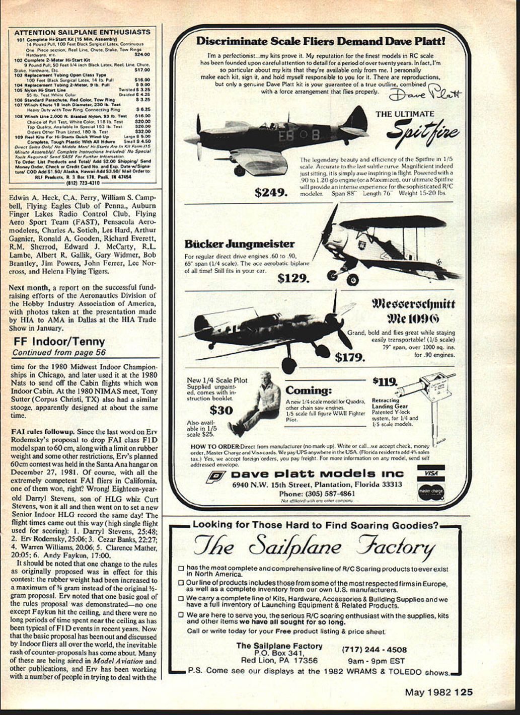
On a number of occasions this column has dealt with the topic of propeller design and construction. Most indoor props are built on blocks carved to form the required helical twist. With this method, a block is required for each propeller which has a different pitch. The photo shows a method first developed by Pete Andrews (I think); since each rib station in an indoor prop must be at a different angle, this fixture allows each rib-station angle to be individually set according to some scheme of prop design.
If you look closely at the photo, the outline of an FAI prop has been fastened to the fixture and to the prop spar, which is visible beginning just to the right of the left-hand support for the central rod. On this rod a number of protractors have been assembled at 1-inch intervals. Each protractor has a bearing and a locking mechanism which holds the protractor at an angle measured from a line that runs along the horizontal bar at the back of the fixture. If a propeller with helical pitch distribution is desired, the blade angle at each station can be calculated.
Prop pitch basics
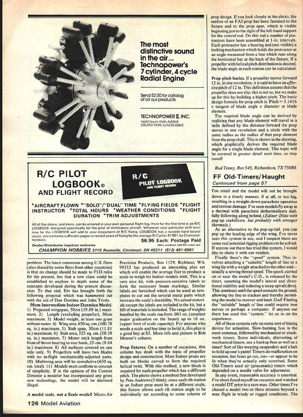
If a propeller moves forward 12 inches in one revolution, it is said to have an effective pitch of 12 inches. This definition assumes that the propeller does not slip; this is not so, but we make up for this by building a higher pitch. The basic design formula for prop pitch is:
Pitch = 3.1416 × tangent of blade angle × diameter at blade element.
The required blade angle can be derived by realizing that any blade element will travel in a helix defined by the distance forward the prop moves in one revolution and a circle with the same radius as the radius of that prop element from the prop shaft. This is shown in the drawing, which graphically derives the required blade angle for a single blade element. This topic will be covered in greater detail next time, so stay tuned!
Bud Tenny, Box 545, Richardson, TX 75080.
Transcribed from original scans by AI. Minor OCR errors may remain.

