

Free Flight: Indoor
Bud Tenny
Prop Pitch Design
Last time we began a design discussion of prop pitch that defined the pitch of a blade element as: Pitch = 3.1416 × tangent(blade angle) × diameter of prop at that blade element.
Let's examine that in a different light. Assume we are examining a blade element at a 5‑in. radius (10‑in. diameter). Also consider prop rpm and model flight velocity. A fairly typical combination could be 50 rpm and 2 ft/sec (24 in/sec) velocity. Working with 50 rpm and 24 in/sec, we can construct a right triangle as shown in Figure 1.
- The base of the triangle represents the distance the blade element moves in one second along its circular path.
- The side adjacent to the angle represents the forward distance the model advances in one second (24 in).
At 50 rpm the prop makes 50/60 = 5/6 revolutions per second. With a 10‑in. diameter, the blade element moves: 10 × 3.1416 × (5/6) ≈ 26.2 in. of circular path while the model advances 24 in.
If you construct the triangle with legs 26.2 and 24, the advance angle is arctan(24/26.2) ≈ 42.6°. Another way to say this is the propeller has an advance angle of 42.6°. If the blade had 0° angle of attack, the blade element angle would be 42.6°, which corresponds to about a 28.8‑in. pitch by the formula above.
However, prop blades usually operate at a small positive angle of attack, typically about 7° (see Figure 2). Working backwards through the formula, a blade angle of 42.6° + 7° = 49.6° corresponds to about a 36.9‑in. pitch. Thus, for a model flying 24 in/sec, a pitch of approximately 36.9 in would give 50 rpm under those conditions.
If that seems like too much calculation, a practical approach is to start with a 32‑in. pitch prop for initial flights, then make flight tests and measurements to determine the next prop size. Trim the model for the minimum reliable forward velocity for the flying conditions: turbulent air usually requires faster flight to avoid stalling, while calm air allows slower flight and often longer duration because the rubber unwinds more slowly at lower rpm.
Measuring Flight Velocity and Advance Angle
Once the model is trimmed the way you want it:
- Wind enough turns so the model climbs about 10 ft above launch and then levels out.
- With a helper, mark the floor at opposite edges of the flight circle.
- Time how long the model takes to make several level circles just after it stops climbing.
- Measure the circle diameter from the floor marks, compute circumference, and divide circumference by time per lap to get average flight velocity.
If you simultaneously measure rpm with a separate stopwatch, you can calculate the advance angle and check prop performance. Keep careful flight performance records, change to a different prop, and repeat. After a few systematic tests you will begin to zero in on the best prop and trim for contest performance.
Motor Attachment: "Glue the Knot!"
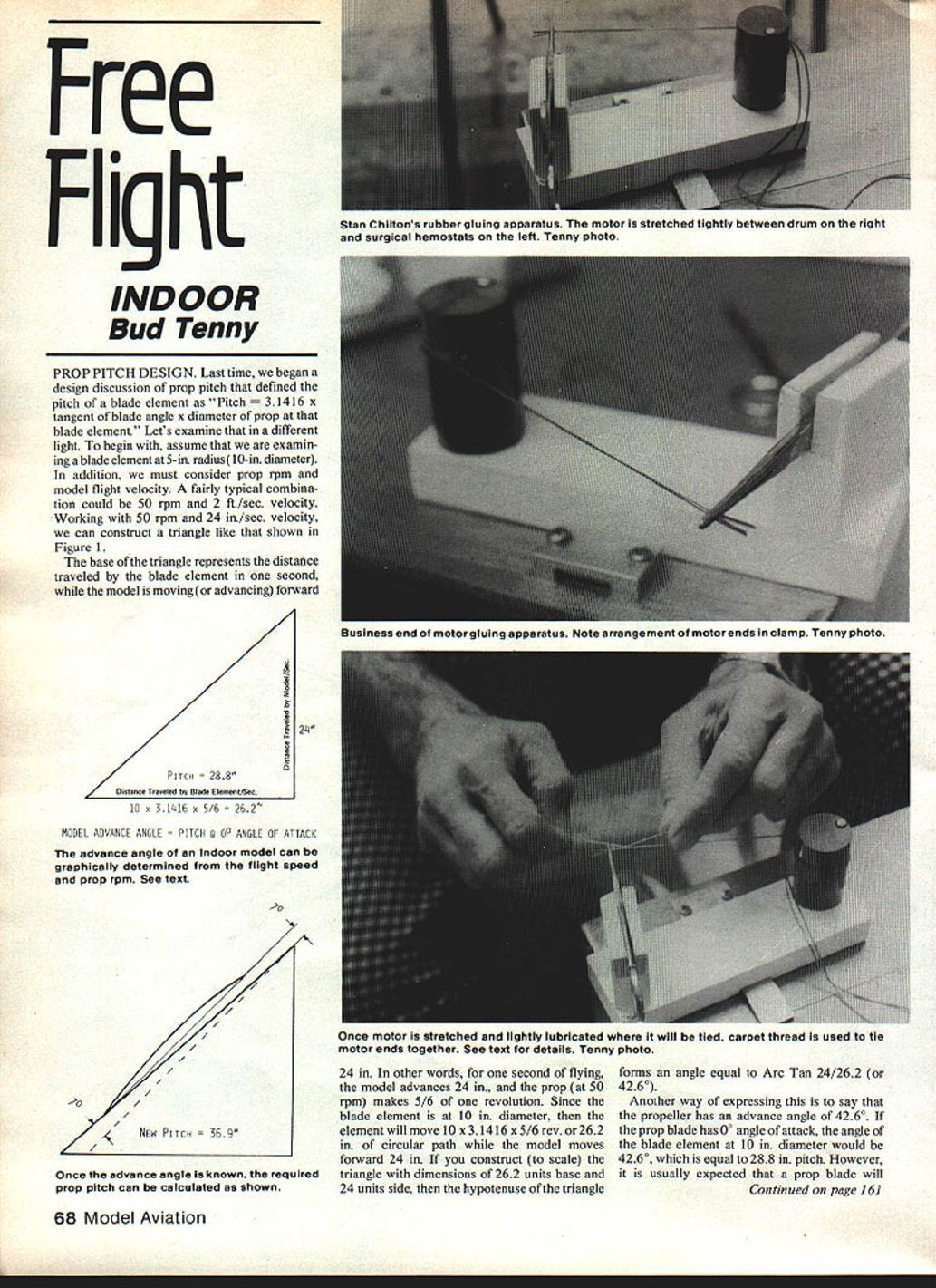
For some time a small number of fliers have been gluing their indoor motors together instead of tying the ends in the traditional way. Pete Andrews used glued motors at the 1972 Indoor World Champs. Stan Chilton is known for many special fixtures; his motor gluing rig is representative.
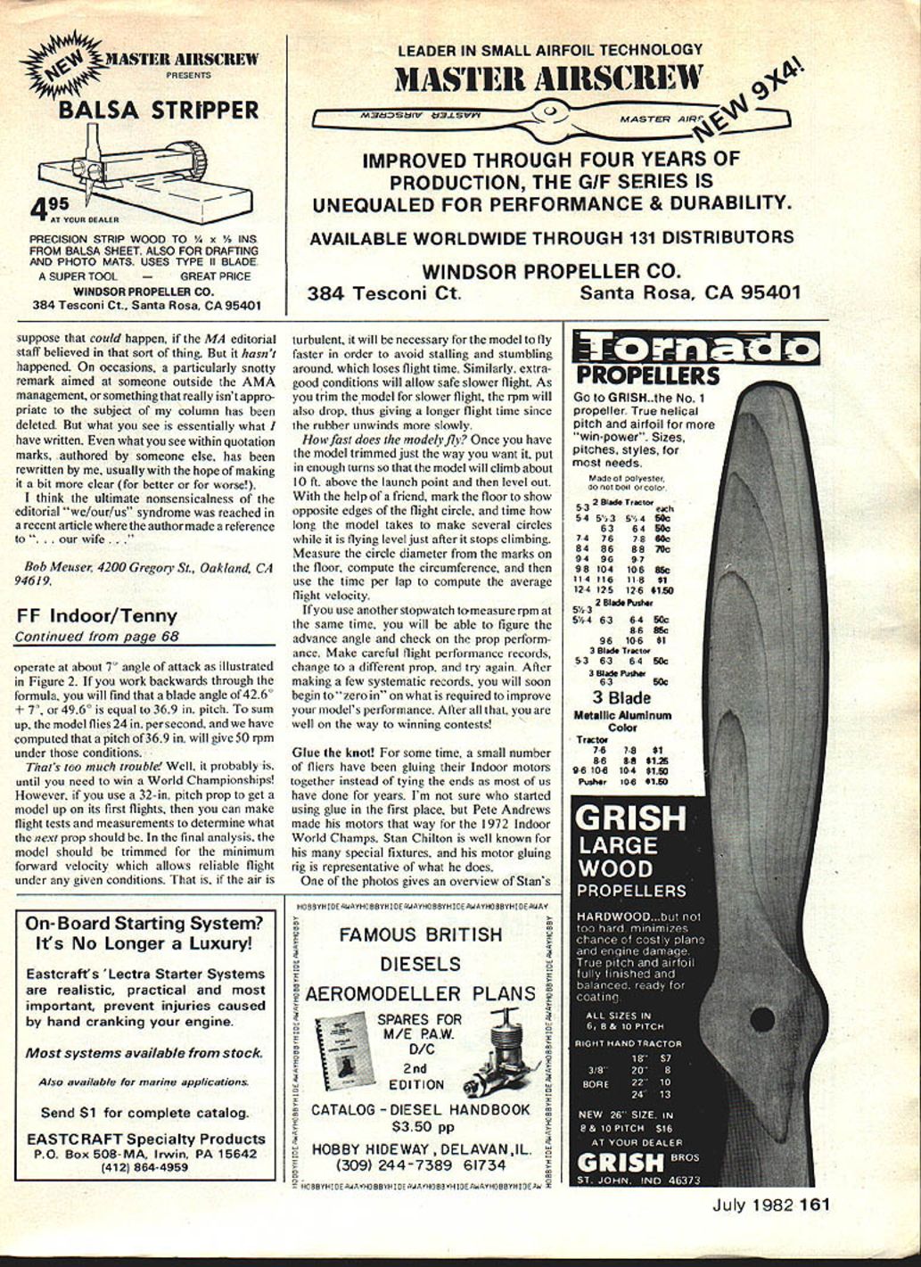
Stan’s apparatus overview:
- A surgical hemostat holds the two ends of the motor on the left.
- The motor is stretched around a drum (used as a winch) to the right; the motor is wrapped so it holds itself to the drum.
- A peg on top of the drum drops into a hole in the fixture base to prevent the drum from turning once locked.
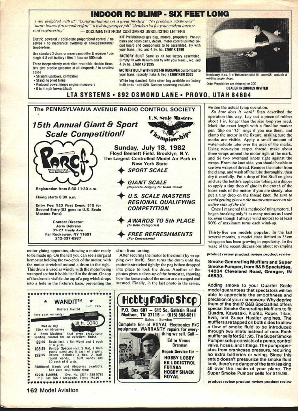
Procedure Stan uses:
- Lay out a piece of rubber about 1 in. longer than the required loop size and mark the exact length with a fine‑line marker.
- Slip on O‑rings if you use them, and clamp the motor in the fixture so the marks are visible.
- Apply a small amount of water‑soluble lubricant over the area of the marks.
- Using non‑nylon carpet thread, make about three wraps around the motor at the mark and tie two overhand knots right against the wraps. From the knot side you should be able to see two wraps of thread.
- Remove the motor from the clamp, wash off the lube thoroughly, and dry carefully.
- Put a drop of Hot Stuff (or similar adhesive) on glass and use the bottle’s applicator tubing as a dipper to apply a tiny drop of glue in the crotch of the loose ends of the motor; if steady, also put a tiny drop on the thread knot. Be sure to avoid getting glue on the active side of the tie or anywhere else on the motor.
After mastering this method I began breaking only about one‑third as many motors as before, even though I always wind motors to at least 90% of maximum turns each wind‑up.
35 cm Models Popular
In the last several months a model class limited to a 35‑cm wingspan has been growing in popularity. Following recent discussions about revamping FAI F1D rules or instituting a special 50‑cm class to explore possible rules configurations for future F1D models, some people have suggested that a 35‑cm class would accomplish the same goals. Whether valid or not, 35‑cm models are now breaking 25 minutes in blimp hangars.
Indoor Week 1982
The week of June 13–20, 1982 will be Indoor Week at West Baden. The week begins with a big Class AAAA‑type indoor meet jointly sponsored by:
- National Free Flight Society (NFFS)
- National Indoor Model Airplane Society (NIMAS)
- Illinois Model Aero Club (IMAC)
- Chicago Aeronuts
This contest will feature 14 model classes, both formal AMA events and non‑AMA events such as Bostonian and two classes of Indoor Speed.
Immediately after that meet, the NIMAS VINART meet will begin, with the III World Peanut Grand Prix intertwined. The Grand Prix will run for 24 hours continuously, beginning at 8 p.m. on June 18. VINART events will share the flying space during June 19. Part of the fun includes three banquets, one for each contest.
If you want more details or to enter, contact: Bud Tenny, P.O. Box 545, Richardson, TX 75080.
Transcribed from original scans by AI. Minor OCR errors may remain.

